EP1513385B1 - Steuergerät reagierend auf Eingangssignale zur Steuerung eines elektronischen Geräts - Google Patents
Steuergerät reagierend auf Eingangssignale zur Steuerung eines elektronischen Geräts Download PDFInfo
- Publication number
- EP1513385B1 EP1513385B1 EP03255466A EP03255466A EP1513385B1 EP 1513385 B1 EP1513385 B1 EP 1513385B1 EP 03255466 A EP03255466 A EP 03255466A EP 03255466 A EP03255466 A EP 03255466A EP 1513385 B1 EP1513385 B1 EP 1513385B1
- Authority
- EP
- European Patent Office
- Prior art keywords
- positioning
- conductive contacts
- cover member
- terminal block
- insertion holes
- Prior art date
- Legal status (The legal status is an assumption and is not a legal conclusion. Google has not performed a legal analysis and makes no representation as to the accuracy of the status listed.)
- Expired - Lifetime
Links
- 238000003780 insertion Methods 0.000 claims abstract description 32
- 230000037431 insertion Effects 0.000 claims abstract description 32
- 239000000523 sample Substances 0.000 claims abstract description 26
- 238000012360 testing method Methods 0.000 claims abstract description 16
- 230000000717 retained effect Effects 0.000 claims description 3
- 230000017525 heat dissipation Effects 0.000 description 1
- 238000000465 moulding Methods 0.000 description 1
Images




Classifications
-
- H—ELECTRICITY
- H05—ELECTRIC TECHNIQUES NOT OTHERWISE PROVIDED FOR
- H05K—PRINTED CIRCUITS; CASINGS OR CONSTRUCTIONAL DETAILS OF ELECTRIC APPARATUS; MANUFACTURE OF ASSEMBLAGES OF ELECTRICAL COMPONENTS
- H05K7/00—Constructional details common to different types of electric apparatus
- H05K7/14—Mounting supporting structure in casing or on frame or rack
- H05K7/1462—Mounting supporting structure in casing or on frame or rack for programmable logic controllers [PLC] for automation or industrial process control
- H05K7/1468—Mechanical features of input/output (I/O) modules
- H05K7/1469—Terminal blocks for connecting sensors
-
- H—ELECTRICITY
- H01—ELECTRIC ELEMENTS
- H01R—ELECTRICALLY-CONDUCTIVE CONNECTIONS; STRUCTURAL ASSOCIATIONS OF A PLURALITY OF MUTUALLY-INSULATED ELECTRICAL CONNECTING ELEMENTS; COUPLING DEVICES; CURRENT COLLECTORS
- H01R9/00—Structural associations of a plurality of mutually-insulated electrical connecting elements, e.g. terminal strips or terminal blocks; Terminals or binding posts mounted upon a base or in a case; Bases therefor
- H01R9/22—Bases, e.g. strip, block, panel
- H01R9/24—Terminal blocks
- H01R9/26—Clip-on terminal blocks for side-by-side rail- or strip-mounting
- H01R9/2625—Clip-on terminal blocks for side-by-side rail- or strip-mounting with built-in electrical component
- H01R9/2666—Clip-on terminal blocks for side-by-side rail- or strip-mounting with built-in electrical component with built-in test-points
-
- H—ELECTRICITY
- H05—ELECTRIC TECHNIQUES NOT OTHERWISE PROVIDED FOR
- H05K—PRINTED CIRCUITS; CASINGS OR CONSTRUCTIONAL DETAILS OF ELECTRIC APPARATUS; MANUFACTURE OF ASSEMBLAGES OF ELECTRICAL COMPONENTS
- H05K5/00—Casings, cabinets or drawers for electric apparatus
- H05K5/02—Details
- H05K5/0247—Electrical details of casings, e.g. terminals, passages for cables or wiring
-
- H—ELECTRICITY
- H05—ELECTRIC TECHNIQUES NOT OTHERWISE PROVIDED FOR
- H05K—PRINTED CIRCUITS; CASINGS OR CONSTRUCTIONAL DETAILS OF ELECTRIC APPARATUS; MANUFACTURE OF ASSEMBLAGES OF ELECTRICAL COMPONENTS
- H05K7/00—Constructional details common to different types of electric apparatus
- H05K7/14—Mounting supporting structure in casing or on frame or rack
- H05K7/1462—Mounting supporting structure in casing or on frame or rack for programmable logic controllers [PLC] for automation or industrial process control
- H05K7/1468—Mechanical features of input/output (I/O) modules
-
- H—ELECTRICITY
- H01—ELECTRIC ELEMENTS
- H01R—ELECTRICALLY-CONDUCTIVE CONNECTIONS; STRUCTURAL ASSOCIATIONS OF A PLURALITY OF MUTUALLY-INSULATED ELECTRICAL CONNECTING ELEMENTS; COUPLING DEVICES; CURRENT COLLECTORS
- H01R13/00—Details of coupling devices of the kinds covered by groups H01R12/70 or H01R24/00 - H01R33/00
- H01R13/46—Bases; Cases
- H01R13/502—Bases; Cases composed of different pieces
Definitions
- the invention relates to a controller module, more particularly to a controller module responsive to input signals for controlling an electrical appliance.
- German utility model No. DE-U-29603161 discloses an electrical connector that is not adapted for use with test probes.
- connection element which is placed in an insulating casing and which comprises at least one connection spring intended to grip the conducting core of a cable to provide an electrical connection between the cable and electrical plant.
- FIGS 1 and 2 illustrate a conventional controller module 1 responsive to input signals for controlling an electrical appliance (not shown).
- the conventional controller module 1 includes a circuit unit 13 disposed in a hollow case 11, a cover member 12, two terminal blocks 14, and two positioning members 15.
- the circuit unit 13 includes two connecting seats 131 (only one is shown) that are exposed from an open end of the case 11.
- the cover member 12 is mounted detachably on the open end of the case 11, and has opposite side walls 123 and a bottom wall 124 in each of opposite lateral sides thereof so as to cooperate with the corresponding connecting seat 131 to confine a block receiving space.
- Each terminal block 14 is mounted detachably in a respective block receiving space through an opening 121 confined by the side walls 123 and is connected electrically to a respective connecting seat 131.
- Each terminal block 14 has a mounting side connected electrically to the corresponding connecting seat 131, a top side formed with a set of probe insertion holes 141 for insertion of a set of test probes 2 (only one is shown in Figure 2), and an input side opposite to the mounting side and formed with a set of input insertion holes 142 for insertion of a set of external terminals (not shown).
- Each positioning member 15 is mounted pivotally on a corresponding lateral side of the cover member 12, and is disposed at the opening 121 in the corresponding lateral side of the cover member 12.
- Each positioning member 15 is formed with opposite pivot posts 151 that are pivotally retained in pivot holes 122 formed in the side walls 123 of the corresponding lateral side of the cover member 12, respectively, and a plurality of positioning posts 152 received in a plurality of positioning holes 143 formed in the input side of the corresponding terminal block 14.
- the terminal blocks 14 can be positioned on the connecting seats 131.
- one of the terminal blocks 14 can be used to connect the circuit unit 13 to an electrical appliance, whereas the other of the terminal blocks 14 can be used to connect the circuit unit 13 to external devices, such as sensors and the like. Accordingly, the circuit unit 13 can control the electrical appliance based on input signals received from the external devices.
- the controller module 1 can be used to control different electrical appliances according to different operating requirements.
- testing of the circuit unit 31 can be conducted through the test probes 2 without the need to remove the circuit unit 13 from the case 11.
- the positioning members 15 must be pivoted upwardly so as to expose the probe insertion holes 141 for insertion of the test probes 2 during testing, thereby resulting in inconvenience.
- the object of the present invention is to provide a controller module that can eliminate the aforesaid drawback of the prior art.
- the controller module 3 includes a circuit unit 8, a hollow case 5, a cover member 6, two terminal blocks 9, and two positioning members 100.
- the circuit unit 8 includes a control circuit 80 adapted to be connected electrically to the electrical appliance, and two connecting seats 81 coupled electrically to the control circuit 80.
- Each connecting seat 81 is formed with a set of first conductive contacts 811, as shown in Figure 3.
- the case 5 has an open end 51.
- the circuit unit 8 is disposed in the case 5 such that the connecting seats 81 of the circuit unit 8 are exposed from the open end 51 of the case 5.
- the case 5 has opposite lateral sides, each of which is formed with a plurality of vent holes 52 for heat dissipation.
- the cover member 6 is mounted detachably on the open end 51 of the case 5.
- the cover member 6 has opposite lateral sides, each of which is formed with first and second openings 60, 61.
- Each lateral side of the cover member 6 has opposite side walls 62, each of which has a pivot edge 621 formed with a pivot groove 63, and a vertical edge 622.
- the pivot edges 621 of the side walls 62 in each lateral side confine the first opening 60.
- the vertical edges 622 of the side walls 62 in each lateral side confine the second opening 61.
- Each lateral side of the cover member 6 further has a bottom wall 65 extending between the side walls 62 and spaced apart from the pivot edges 621 of the side walls 62.
- Each connecting seat 81 of the circuit unit 8 is spaced apart from the vertical edges 622 of the side walls 62 in a corresponding one of the lateral sides by the bottom wall 65.
- the side walls 62, the bottom wall 65 and a corresponding one of the connecting seats 81 cooperate to confine a block receiving space 64.
- each pivot groove 63 has a restricted upper neck portion 631 and a wider lower receiving portion 632, and is formed during molding of the cover member 6.
- Each terminal block 9 is mounted detachably in the block receiving space 64 through the second opening 61 in a corresponding one of the lateral sides of the cover member 6 such that each terminal block 9 is accessible through the second opening 61 in the corresponding one of the lateral sides of the cover member 6.
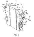
- Each terminal block 9 has a mounting side 94 provided with a set of second conductive contacts 941 that are each connected electrically and removably to a first conductive contact 811 in a corresponding one of the connecting seats 81, and an input side 93 opposite to the mounting side 94 and formed with a set of input insertion holes 931 adapted for insertion of a set of external terminals 110 (see Figure 5) so as to permit connection of the external terminals 110 to the first conductive contacts 811 in the corresponding one of the connecting seats 81 through the second conductive contacts 941 and a top side 91 formed with a set of probe insertion holes 92 adapted for insertion of a set of test probes 4 (only one is shown in Figure 5) so as to permit connection of the test probes 4 to the first conductive contacts 811 in the corresponding one of the connecting seats 81 through the second conductive contacts 941.
- the positioning members 100 are mounted pivotally on the lateral sides of the cover member 6. Each positioning member 100 is disposed at the first opening 60 in a corresponding one of the lateral sides of the cover member 6 for positioning a respective terminal block 9 on the corresponding connecting seat 81. Each positioning member 100 has a first plate body 102 disposed above the top side 91 of the respective terminal block 9 and formed with a set of positioning holes 103 that are registered with the probe insertion holes 92 in the top side 91 of the respective terminal block 9, and a second plate body 104 connected to the first plate body 102, extending into the second opening 61 in the corresponding one of the lateral sides of the cover member 6 and engaging the input side 93 of the corresponding one of the terminal blocks 9 without covering the input insertion holes 931.
- each positioning member 100 is formed with opposite pivot posts 101 that are pivotally retained in the pivot grooves 63 in the side walls 62 of the corresponding one of the lateral sides of the cover member 6, as shown in Figure 5.
- each pivot post 101 is received in the lower receiving portion 632 of a corresponding one of the pivot grooves 63, and has a size larger than that of the upper neck portion 631 and smaller than that of the lower receiving portion 632.
- FIGS 6 and 7 illustrate the second preferred embodiment of a controller module 3' according to this invention, which is amodificationof the first preferred embodiment.
- each positioning member 100' further has a third plate body 105 with a connecting portion 1051 connected to a junction of the first and second plate bodies 102, 104, and a positioning portion 1052 connected to the connecting portion 1051 and extending parallel to the second plate body 104.
- the positioning portion 1052 is formed with a set of notches 1053 registered with the input insertion holes 931 in the input side 93 of the corresponding terminal block 9.
- the test probes 4 can be directly inserted into the probe insertion holes 92 in the terminal blocks 9 through the positioning holes 103 without pivoting the positioning members 100, 100', thereby resulting in convenience during use. Furthermore, reliable positioning of the test probes 4 can be ensured.
Landscapes
- Engineering & Computer Science (AREA)
- Microelectronics & Electronic Packaging (AREA)
- Automation & Control Theory (AREA)
- Connections Arranged To Contact A Plurality Of Conductors (AREA)
- Connector Housings Or Holding Contact Members (AREA)
- Coupling Device And Connection With Printed Circuit (AREA)
- Electrophonic Musical Instruments (AREA)
- Selective Calling Equipment (AREA)
Claims (4)
- Steuermodul (3, 3'), das auf Eingangssignale zum Steuern eines elektrischen Geräts anspricht, wobei das genannte Steuermodul (3, 3') gekennzeichnet ist durch:eine Schaltungseinheit (8) mit einer Steuerschaltung (80) zum elektrischen Verbinden mit dem elektrischen Gerät und einem Verbindungssitz (81), der elektrisch mit der genannten Steuerschaltung (80) gekoppelt ist und mit einem Satz erster leitender Kontakte (811) ausgebildet ist;ein hohles Gehäuse (5) mit einem offenen Ende (51), wobei die genannte Schaltungseinheit (8) so in dem genannten Gehäuse (5) angeordnet ist, dass der genannte Verbindungssitz (81) der genannten Schaltungseinheit (8) vom genannten offenen Ende (51) des genannten Gehäuses (5) offenliegt;ein abnehmbar am genannten offenen Ende (51) des genannten Gehäuses (5) montiertes Deckelelement (6), wobei das genannte Deckelelement (6) mit einer ersten und einer zweiten Öffnung (60, 61) ausgebildet ist, wobei das genannte Deckelelement (6) einander gegenüberliegende Seitenwände (62) hat, die jeweils einen mit einer Gelenknut (63) ausgebildeten Gelenkrand (621) und einen vertikalen Rand (622) haben, wobei die genannten Gelenkränder (621) der genannten Seitenwände (62) die genannte erste Öffnung (60) begrenzen, wobei die genannten vertikalen Ränder (622) der genannten Seitenwände (62) die genannte zweite Öffnung (61) begrenzen, wobei das genannte Deckelelement (6) ferner eine untere Wand (65) hat, die zwischen den genannten Seitenwänden (62) verläuft und von den genannten Gelenkrändern (621) der genannten Seitenwände (62) beabstandet ist, wobei der genannte Verbindungssitz (81) der genannten Schaltungseinheit (8) durch die genannte untere Wand (65) von den genannten vertikalen Rändern (622) der genannten Seitenwände (62) beabstandet ist, wobei die genannten Seitenwände (62), die genannte untere Wand (65) und der genannte Verbindungssitz (81) zum Begrenzen eines Blockaufnahmeraums (64) zusammenwirken;einen Klemmenblock (9), der durch die genannte zweite Öffnung (61) in dem genannten Deckelelement (6) abnehmbar in dem genannten Blockaufnahmeraum (64) montiert ist, so dass der genannte Klemmenblock (9) durch die genannte zweite Öffnung (61) zugänglich ist, wobei der genannte Klemmenblock (9) Folgendes hat: eine Befestigungsseite (94), die mit einem Satz zweiter leitender Kontakte (941) versehen ist, die jeweils elektrisch und abnehmbar mit einem der genannten ersten leitenden Kontakte (811) verbunden sind, eine Eingangsseite (93), die der genannten Befestigungsseite (94) entgegengesetzt und mit einem Satz Eingangseinstecklöchern (931) zum Einführen eines Satzes externer Anschlüsse (110) ausgebildet ist, um das Verbinden der externen Anschlüsse (110) mit den genannten ersten leitenden Kontakten (811) durch die genannten zweiten leitenden Kontakte (941) zuzulassen, und eine Oberseite (91), die mit einem Satz von Sondeneinstecklöchern (92) zum Einführen eines Satzes von Prüfsonden (4) ausgebildet ist, um das Verbinden der Prüfsonden (4) mit den genannten ersten leitenden Kontakten (811) durch die genannten zweiten leitenden Kontakte (941) zuzulassen; undein Positionierungselement (100, 100'), das am genannten Deckelelement (6) angelenkt ist und an der genannten ersten Öffnung (60) im genannten Deckelelement (6) angeordnet ist, zum Positionieren des genannten Klemmenblocks (9) an dem genannten Verbindungssitz (81), wobei das genannte Positionierungselement (100, 100') einen ersten Plattenkörper (102), der über der genannten Oberseite (91) des genannten Klemmenblocks (9) angeordnet und mit einem Satz Positionierungslöcher (103) ausgebildet ist, die mit den genannten Sondeneinstecklöchern (92) in der genannten Oberseite (91) des genannten Klemmenblocks (9) lagegenau sind, und einen mit dem genannten ersten Plattenkörper (102) verbundenen zweiten Plattenkörper (104) hat, der sich in die genannte zweite Öffnung (61) im genannten Deckelelement (6) erstreckt und mit der genannten Eingangsseite (93) des genannten Klemmenblocks (9) in Eingriff ist, ohne die genannten Eingangseinstecklöcher (931) zu bedecken, wobei der genannte erste Plattenkörper (102) mit einander entgegengesetzten Drehzapfen (101) ausgebildet ist, die in den genannten Gelenknuten (63) gelenkig festgehalten werden, und wodurch die Prüfsonden (4) durch die genannten Positionierungslöcher (103) direkt in die genannten Sondeneinstecklöcher (92) eingeführt werden können, ohne das genannte Positionierungselement (100, 100') zu schwenken, wodurch das genannte Modul im Gebrauch bedienungsfreundlich ist.
- Steuermodul nach Anspruch 1, bei dem jede der genannten Gelenknuten (63) einen verengten oberen Halsabschnitt (631) und einen weiteren unteren Aufnahmeabschnitt (632) hat, wobei jeder der genannten Drehzapfen (101) in dem genannten unteren Aufnahmeabschnitt (632) aufgenommen wird und eine Größe hat, die größer als die des genannten oberen Halsabschnitts (631) und kleiner als die des genannten unteren Aufnahmeabschnitts (632) ist.
- Steuermodul nach Anspruch 1 oder 2, bei dem das genannte Positionierungselement (100') ferner einen dritten Plattenkörper (105) hat mit einem Verbindungsabschnitt (1051), der mit einer Verbindungsstelle des genannten ersten und zweiten Plattenkörpers (102, 104) verbunden ist, und einem Positionierungsabschnitt (1052), der mit dem genannten Verbindungsabschnitt (1051) verbunden ist und parallel zum genannten zweiten Plattenkörper (104) verläuft, wobei der genannte Positionierungsabschnitt (1052) mit einem Satz Aussparungen (1053) ausgebildet ist, die mit den genannten Eingangseinstecklöchern (931) lagegenau sind.
- Steuermodul für ein elektrisches Gerät, umfassend eine Schaltungseinheit (8), die in einem Gehäuse (5) angeordnet ist und an einem offenen Ende (51) des Gehäuses (5) offen liegt und elektrisch mit einer Steuerschaltung (80) in dem Gehäuse (5) gekoppelt ist, einen Verbindungssitz (81) mit einem Satz erster leitender Kontakte (811),
einen Klemmenblock (9), der abnehmbar in dem Gehäuse montiert ist und eine Befestigungsseite (94) hat, die mit zweiten leitenden Kontakten (941) versehen ist, die abnehmbar mit jeweiligen der ersten leitenden Kontakte (811) verbunden sind,
eine Eingangsseite (93), die der genannten Befestigungsseite (94) entgegengesetzt und mit Eingangseinstecklöchern (931) zum Einführen externer Anschlüsse (110) ausgebildet ist, und eine Oberseite (91), die mit Sondeneinstecklöchern (92) zum Einführen von Prüfsonden (4) ausgebildet ist,
und ein Positionierungselement (100), das am Gehäuse (5) angelenkt ist zum Positionieren des Klemmenblocks (9) an dem Verbindungssitz (81) und mit entsprechenden Positionierungslöchern (103) versehen ist,
und wobei die Prüfsonden (4) durch die Positionierungslöcher (103) direkt in die Sondeneinstecklöcher (92) eingeführt werden können, ohne das Positionierungselement (100) zu schwenken, wodurch das Modul im Gebrauch bedienungsfreundlich ist.
Priority Applications (3)
| Application Number | Priority Date | Filing Date | Title |
|---|---|---|---|
| AT03255466T ATE377347T1 (de) | 2003-09-02 | 2003-09-02 | Steuergerät reagierend auf eingangssignale zur steuerung eines elektronischen geräts |
| EP03255466A EP1513385B1 (de) | 2003-09-02 | 2003-09-02 | Steuergerät reagierend auf Eingangssignale zur Steuerung eines elektronischen Geräts |
| DE60317196T DE60317196T2 (de) | 2003-09-02 | 2003-09-02 | Steuergerät reagierend auf Eingangssignale zur Steuerung eines elektronischen Geräts |
Applications Claiming Priority (1)
| Application Number | Priority Date | Filing Date | Title |
|---|---|---|---|
| EP03255466A EP1513385B1 (de) | 2003-09-02 | 2003-09-02 | Steuergerät reagierend auf Eingangssignale zur Steuerung eines elektronischen Geräts |
Publications (2)
| Publication Number | Publication Date |
|---|---|
| EP1513385A1 EP1513385A1 (de) | 2005-03-09 |
| EP1513385B1 true EP1513385B1 (de) | 2007-10-31 |
Family
ID=34130337
Family Applications (1)
| Application Number | Title | Priority Date | Filing Date |
|---|---|---|---|
| EP03255466A Expired - Lifetime EP1513385B1 (de) | 2003-09-02 | 2003-09-02 | Steuergerät reagierend auf Eingangssignale zur Steuerung eines elektronischen Geräts |
Country Status (3)
| Country | Link |
|---|---|
| EP (1) | EP1513385B1 (de) |
| AT (1) | ATE377347T1 (de) |
| DE (1) | DE60317196T2 (de) |
Families Citing this family (2)
| Publication number | Priority date | Publication date | Assignee | Title |
|---|---|---|---|---|
| DE202012102325U1 (de) * | 2012-06-25 | 2012-09-06 | Wago Verwaltungsgesellschaft Mbh | Elektronikgerätegehäuse |
| JP6904940B2 (ja) * | 2018-11-22 | 2021-07-21 | 矢崎総業株式会社 | コネクタ |
Family Cites Families (4)
| Publication number | Priority date | Publication date | Assignee | Title |
|---|---|---|---|---|
| DE19601518B4 (de) * | 1996-01-17 | 2016-05-12 | Wabco Gmbh | Gehäuse für eine elektrische Baugruppe |
| DE29603161U1 (de) * | 1996-02-22 | 1996-05-15 | Gebr. Merten Gmbh & Co Kg, 51643 Gummersbach | Abdeckung für ein elektrisches Gehäuse |
| DE19746591A1 (de) * | 1997-10-22 | 1999-04-29 | Abb Patent Gmbh | Elektrisches Gerät |
| FR2824960B1 (fr) * | 2001-05-15 | 2003-08-15 | Entrelec | Dispositif de raccordement a poussoir |
-
2003
- 2003-09-02 AT AT03255466T patent/ATE377347T1/de not_active IP Right Cessation
- 2003-09-02 DE DE60317196T patent/DE60317196T2/de not_active Expired - Lifetime
- 2003-09-02 EP EP03255466A patent/EP1513385B1/de not_active Expired - Lifetime
Also Published As
| Publication number | Publication date |
|---|---|
| DE60317196D1 (de) | 2007-12-13 |
| ATE377347T1 (de) | 2007-11-15 |
| EP1513385A1 (de) | 2005-03-09 |
| DE60317196T2 (de) | 2008-08-14 |
Similar Documents
| Publication | Publication Date | Title |
|---|---|---|
| US5203716A (en) | Terminal block for printed circuit boards | |
| CN2562408Y (zh) | 电池连接器 | |
| US5064387A (en) | Shielded electrical jack connector | |
| US6328605B1 (en) | Electrical connector for receiving module cards and an operating circuit card | |
| US4354718A (en) | Dual-in-line package carrier and socket assembly | |
| US7252517B2 (en) | Electric connector | |
| US6811425B1 (en) | Controller module responsive to input signals for controlling an electrical appliance | |
| US4415214A (en) | Electrical plug and socket connectors | |
| JPH08249013A (ja) | インタフェース装置 | |
| CN201029150Y (zh) | 电连接器 | |
| KR102102588B1 (ko) | 플러그 장치 및 배전 시스템 | |
| US6709299B2 (en) | Plug-in module, carrier plate and relay arrangement | |
| US20110059634A1 (en) | Electrcial connector with abutting ribs against pcb | |
| CN212934497U (zh) | 一种带数据管理模块的塑壳断路器 | |
| CN102456955B (zh) | 用于导线端子的桥接结构 | |
| EP1513385A1 (de) | Steuergerät reagierend auf Eingangssignale zur Steuerung eines elektronischen Geräts | |
| JP2004103263A (ja) | 端子台 | |
| US8398410B2 (en) | Socket connector having carbon nanotube contacts for signal transmission and metallic contacts for power transmission | |
| JP3085686U (ja) | 多方向式コンセント | |
| US6174195B1 (en) | Ribbon cable connector with unitary conductive members for connecting respectively and electricity selected signal terminals to a grounding plate | |
| CN218070254U (zh) | 一种连接器及终端 | |
| JP3067506U (ja) | 多受口ソケット構造 | |
| CN219087661U (zh) | 散热装置 | |
| CN217115060U (zh) | 一种接插组件及其接插装置 | |
| US5062805A (en) | Structure of cable connector for matching with IC mounting seat |
Legal Events
| Date | Code | Title | Description |
|---|---|---|---|
| PUAI | Public reference made under article 153(3) epc to a published international application that has entered the european phase |
Free format text: ORIGINAL CODE: 0009012 |
|
| AK | Designated contracting states |
Kind code of ref document: A1 Designated state(s): AT BE BG CH CY CZ DE DK EE ES FI FR GB GR HU IE IT LI LU MC NL PT RO SE SI SK TR |
|
| AX | Request for extension of the european patent |
Extension state: AL LT LV MK |
|
| 17P | Request for examination filed |
Effective date: 20050908 |
|
| AKX | Designation fees paid |
Designated state(s): AT BE BG CH CY CZ DE DK EE ES FI FR GB GR HU IE IT LI LU MC NL PT RO SE SI SK TR |
|
| GRAP | Despatch of communication of intention to grant a patent |
Free format text: ORIGINAL CODE: EPIDOSNIGR1 |
|
| GRAS | Grant fee paid |
Free format text: ORIGINAL CODE: EPIDOSNIGR3 |
|
| GRAA | (expected) grant |
Free format text: ORIGINAL CODE: 0009210 |
|
| AK | Designated contracting states |
Kind code of ref document: B1 Designated state(s): AT BE BG CH CY CZ DE DK EE ES FI FR GB GR HU IE IT LI LU MC NL PT RO SE SI SK TR |
|
| REG | Reference to a national code |
Ref country code: GB Ref legal event code: FG4D |
|
| REG | Reference to a national code |
Ref country code: IE Ref legal event code: FG4D |
|
| REG | Reference to a national code |
Ref country code: CH Ref legal event code: EP |
|
| REF | Corresponds to: |
Ref document number: 60317196 Country of ref document: DE Date of ref document: 20071213 Kind code of ref document: P |
|
| NLV1 | Nl: lapsed or annulled due to failure to fulfill the requirements of art. 29p and 29m of the patents act | ||
| PG25 | Lapsed in a contracting state [announced via postgrant information from national office to epo] |
Ref country code: LI Free format text: LAPSE BECAUSE OF FAILURE TO SUBMIT A TRANSLATION OF THE DESCRIPTION OR TO PAY THE FEE WITHIN THE PRESCRIBED TIME-LIMIT Effective date: 20071031 Ref country code: SE Free format text: LAPSE BECAUSE OF FAILURE TO SUBMIT A TRANSLATION OF THE DESCRIPTION OR TO PAY THE FEE WITHIN THE PRESCRIBED TIME-LIMIT Effective date: 20080131 Ref country code: NL Free format text: LAPSE BECAUSE OF FAILURE TO SUBMIT A TRANSLATION OF THE DESCRIPTION OR TO PAY THE FEE WITHIN THE PRESCRIBED TIME-LIMIT Effective date: 20071031 Ref country code: CH Free format text: LAPSE BECAUSE OF FAILURE TO SUBMIT A TRANSLATION OF THE DESCRIPTION OR TO PAY THE FEE WITHIN THE PRESCRIBED TIME-LIMIT Effective date: 20071031 Ref country code: ES Free format text: LAPSE BECAUSE OF FAILURE TO SUBMIT A TRANSLATION OF THE DESCRIPTION OR TO PAY THE FEE WITHIN THE PRESCRIBED TIME-LIMIT Effective date: 20080211 |
|
| REG | Reference to a national code |
Ref country code: CH Ref legal event code: PL |
|
| PG25 | Lapsed in a contracting state [announced via postgrant information from national office to epo] |
Ref country code: PT Free format text: LAPSE BECAUSE OF FAILURE TO SUBMIT A TRANSLATION OF THE DESCRIPTION OR TO PAY THE FEE WITHIN THE PRESCRIBED TIME-LIMIT Effective date: 20080331 Ref country code: SI Free format text: LAPSE BECAUSE OF FAILURE TO SUBMIT A TRANSLATION OF THE DESCRIPTION OR TO PAY THE FEE WITHIN THE PRESCRIBED TIME-LIMIT Effective date: 20071031 Ref country code: BG Free format text: LAPSE BECAUSE OF FAILURE TO SUBMIT A TRANSLATION OF THE DESCRIPTION OR TO PAY THE FEE WITHIN THE PRESCRIBED TIME-LIMIT Effective date: 20080131 |
|
| PG25 | Lapsed in a contracting state [announced via postgrant information from national office to epo] |
Ref country code: AT Free format text: LAPSE BECAUSE OF FAILURE TO SUBMIT A TRANSLATION OF THE DESCRIPTION OR TO PAY THE FEE WITHIN THE PRESCRIBED TIME-LIMIT Effective date: 20071031 |
|
| PG25 | Lapsed in a contracting state [announced via postgrant information from national office to epo] |
Ref country code: CZ Free format text: LAPSE BECAUSE OF FAILURE TO SUBMIT A TRANSLATION OF THE DESCRIPTION OR TO PAY THE FEE WITHIN THE PRESCRIBED TIME-LIMIT Effective date: 20071031 Ref country code: DK Free format text: LAPSE BECAUSE OF FAILURE TO SUBMIT A TRANSLATION OF THE DESCRIPTION OR TO PAY THE FEE WITHIN THE PRESCRIBED TIME-LIMIT Effective date: 20071031 |
|
| EN | Fr: translation not filed | ||
| PG25 | Lapsed in a contracting state [announced via postgrant information from national office to epo] |
Ref country code: BE Free format text: LAPSE BECAUSE OF FAILURE TO SUBMIT A TRANSLATION OF THE DESCRIPTION OR TO PAY THE FEE WITHIN THE PRESCRIBED TIME-LIMIT Effective date: 20071031 Ref country code: RO Free format text: LAPSE BECAUSE OF FAILURE TO SUBMIT A TRANSLATION OF THE DESCRIPTION OR TO PAY THE FEE WITHIN THE PRESCRIBED TIME-LIMIT Effective date: 20071031 Ref country code: SK Free format text: LAPSE BECAUSE OF FAILURE TO SUBMIT A TRANSLATION OF THE DESCRIPTION OR TO PAY THE FEE WITHIN THE PRESCRIBED TIME-LIMIT Effective date: 20071031 |
|
| PLBE | No opposition filed within time limit |
Free format text: ORIGINAL CODE: 0009261 |
|
| STAA | Information on the status of an ep patent application or granted ep patent |
Free format text: STATUS: NO OPPOSITION FILED WITHIN TIME LIMIT |
|
| 26N | No opposition filed |
Effective date: 20080801 |
|
| PG25 | Lapsed in a contracting state [announced via postgrant information from national office to epo] |
Ref country code: FR Free format text: LAPSE BECAUSE OF FAILURE TO SUBMIT A TRANSLATION OF THE DESCRIPTION OR TO PAY THE FEE WITHIN THE PRESCRIBED TIME-LIMIT Effective date: 20080704 |
|
| PG25 | Lapsed in a contracting state [announced via postgrant information from national office to epo] |
Ref country code: GR Free format text: LAPSE BECAUSE OF FAILURE TO SUBMIT A TRANSLATION OF THE DESCRIPTION OR TO PAY THE FEE WITHIN THE PRESCRIBED TIME-LIMIT Effective date: 20080201 |
|
| PG25 | Lapsed in a contracting state [announced via postgrant information from national office to epo] |
Ref country code: FI Free format text: LAPSE BECAUSE OF FAILURE TO SUBMIT A TRANSLATION OF THE DESCRIPTION OR TO PAY THE FEE WITHIN THE PRESCRIBED TIME-LIMIT Effective date: 20071031 |
|
| PG25 | Lapsed in a contracting state [announced via postgrant information from national office to epo] |
Ref country code: MC Free format text: LAPSE BECAUSE OF NON-PAYMENT OF DUE FEES Effective date: 20080930 Ref country code: EE Free format text: LAPSE BECAUSE OF FAILURE TO SUBMIT A TRANSLATION OF THE DESCRIPTION OR TO PAY THE FEE WITHIN THE PRESCRIBED TIME-LIMIT Effective date: 20071031 |
|
| PG25 | Lapsed in a contracting state [announced via postgrant information from national office to epo] |
Ref country code: CY Free format text: LAPSE BECAUSE OF FAILURE TO SUBMIT A TRANSLATION OF THE DESCRIPTION OR TO PAY THE FEE WITHIN THE PRESCRIBED TIME-LIMIT Effective date: 20071031 Ref country code: IE Free format text: LAPSE BECAUSE OF NON-PAYMENT OF DUE FEES Effective date: 20080902 |
|
| PG25 | Lapsed in a contracting state [announced via postgrant information from national office to epo] |
Ref country code: LU Free format text: LAPSE BECAUSE OF NON-PAYMENT OF DUE FEES Effective date: 20080902 Ref country code: HU Free format text: LAPSE BECAUSE OF FAILURE TO SUBMIT A TRANSLATION OF THE DESCRIPTION OR TO PAY THE FEE WITHIN THE PRESCRIBED TIME-LIMIT Effective date: 20080501 |
|
| PG25 | Lapsed in a contracting state [announced via postgrant information from national office to epo] |
Ref country code: TR Free format text: LAPSE BECAUSE OF FAILURE TO SUBMIT A TRANSLATION OF THE DESCRIPTION OR TO PAY THE FEE WITHIN THE PRESCRIBED TIME-LIMIT Effective date: 20071031 |
|
| PG25 | Lapsed in a contracting state [announced via postgrant information from national office to epo] |
Ref country code: IT Free format text: LAPSE BECAUSE OF NON-PAYMENT OF DUE FEES Effective date: 20080930 |
|
| PGFP | Annual fee paid to national office [announced via postgrant information from national office to epo] |
Ref country code: GB Payment date: 20150706 Year of fee payment: 13 |
|
| PGFP | Annual fee paid to national office [announced via postgrant information from national office to epo] |
Ref country code: DE Payment date: 20160330 Year of fee payment: 14 |
|
| GBPC | Gb: european patent ceased through non-payment of renewal fee |
Effective date: 20160902 |
|
| PG25 | Lapsed in a contracting state [announced via postgrant information from national office to epo] |
Ref country code: GB Free format text: LAPSE BECAUSE OF NON-PAYMENT OF DUE FEES Effective date: 20160902 |
|
| REG | Reference to a national code |
Ref country code: DE Ref legal event code: R119 Ref document number: 60317196 Country of ref document: DE |
|
| PG25 | Lapsed in a contracting state [announced via postgrant information from national office to epo] |
Ref country code: DE Free format text: LAPSE BECAUSE OF NON-PAYMENT OF DUE FEES Effective date: 20180404 |