EP1513232A1 - Dispositif laser et procédé de fonctionnement du dispositif laser - Google Patents
Dispositif laser et procédé de fonctionnement du dispositif laser Download PDFInfo
- Publication number
- EP1513232A1 EP1513232A1 EP03020178A EP03020178A EP1513232A1 EP 1513232 A1 EP1513232 A1 EP 1513232A1 EP 03020178 A EP03020178 A EP 03020178A EP 03020178 A EP03020178 A EP 03020178A EP 1513232 A1 EP1513232 A1 EP 1513232A1
- Authority
- EP
- European Patent Office
- Prior art keywords
- laser device
- laser
- solid
- active region
- state laser
- Prior art date
- Legal status (The legal status is an assumption and is not a legal conclusion. Google has not performed a legal analysis and makes no representation as to the accuracy of the status listed.)
- Withdrawn
Links
- 238000000034 method Methods 0.000 title claims abstract description 12
- 230000005855 radiation Effects 0.000 claims abstract description 52
- 238000005086 pumping Methods 0.000 claims abstract description 23
- 239000004065 semiconductor Substances 0.000 claims abstract description 15
- 239000007787 solid Substances 0.000 claims description 45
- 238000010521 absorption reaction Methods 0.000 claims description 3
- 230000006978 adaptation Effects 0.000 claims description 3
- 238000001816 cooling Methods 0.000 claims 2
- 230000003287 optical effect Effects 0.000 description 6
- 238000001228 spectrum Methods 0.000 description 3
- 239000003795 chemical substances by application Substances 0.000 description 2
- 239000000463 material Substances 0.000 description 2
- 238000002835 absorbance Methods 0.000 description 1
- 238000003491 array Methods 0.000 description 1
- 238000011161 development Methods 0.000 description 1
- 230000018109 developmental process Effects 0.000 description 1
- 239000013307 optical fiber Substances 0.000 description 1
- 230000035515 penetration Effects 0.000 description 1
Images


Classifications
-
- H—ELECTRICITY
- H01—ELECTRIC ELEMENTS
- H01S—DEVICES USING THE PROCESS OF LIGHT AMPLIFICATION BY STIMULATED EMISSION OF RADIATION [LASER] TO AMPLIFY OR GENERATE LIGHT; DEVICES USING STIMULATED EMISSION OF ELECTROMAGNETIC RADIATION IN WAVE RANGES OTHER THAN OPTICAL
- H01S3/00—Lasers, i.e. devices using stimulated emission of electromagnetic radiation in the infrared, visible or ultraviolet wave range
- H01S3/09—Processes or apparatus for excitation, e.g. pumping
- H01S3/091—Processes or apparatus for excitation, e.g. pumping using optical pumping
- H01S3/094—Processes or apparatus for excitation, e.g. pumping using optical pumping by coherent light
- H01S3/0941—Processes or apparatus for excitation, e.g. pumping using optical pumping by coherent light of a laser diode
-
- H—ELECTRICITY
- H01—ELECTRIC ELEMENTS
- H01S—DEVICES USING THE PROCESS OF LIGHT AMPLIFICATION BY STIMULATED EMISSION OF RADIATION [LASER] TO AMPLIFY OR GENERATE LIGHT; DEVICES USING STIMULATED EMISSION OF ELECTROMAGNETIC RADIATION IN WAVE RANGES OTHER THAN OPTICAL
- H01S3/00—Lasers, i.e. devices using stimulated emission of electromagnetic radiation in the infrared, visible or ultraviolet wave range
- H01S3/02—Constructional details
- H01S3/04—Arrangements for thermal management
- H01S3/042—Arrangements for thermal management for solid state lasers
-
- H—ELECTRICITY
- H01—ELECTRIC ELEMENTS
- H01S—DEVICES USING THE PROCESS OF LIGHT AMPLIFICATION BY STIMULATED EMISSION OF RADIATION [LASER] TO AMPLIFY OR GENERATE LIGHT; DEVICES USING STIMULATED EMISSION OF ELECTROMAGNETIC RADIATION IN WAVE RANGES OTHER THAN OPTICAL
- H01S3/00—Lasers, i.e. devices using stimulated emission of electromagnetic radiation in the infrared, visible or ultraviolet wave range
- H01S3/23—Arrangements of two or more lasers not provided for in groups H01S3/02 - H01S3/22, e.g. tandem arrangements of separate active media
- H01S3/2383—Parallel arrangements
Definitions
- the present invention relates to a laser device comprising at least one solid-state laser unit with at least one active Area in which laser radiation can be generated, as well at least one semiconductor laser device, the pumping light for the optical pumps of the at least one active region of the can generate at least one solid-state laser unit.
- the present invention relates to a method for operating a Such a laser device according to the preamble of the claim 18th
- this slab consists of three Layers, namely a middle active area, the for example, consists of Nd: YAG, as well as two outer Layers sandwiching the middle layer, wherein these two outer layers, for example, undoped YAG can exist.
- a middle active area the for example, consists of Nd: YAG
- two outer Layers sandwiching the middle layer wherein these two outer layers, for example, undoped YAG can exist.
- the surrounded Layers of undoped material can be used for example for Pump light bundling serve.
- the surrounding ones ensure undoped layers that in the pumping light source facing Edge areas of the active layer no losses on exit from Edge areas occur because of the edges of the active Layer the outer layers connect seamlessly.
- the problem underlying the present invention is the Creation of a laser device of the type mentioned, in which with simple means a comparatively small divergence of the laser device generated laser beam can be achieved. Furthermore, a method for operating the aforementioned type be given, with a laser beam with comparatively small divergence can be generated.
- the laser device so is formed that the pump light during operation of the Laser device in the at least one active area a Plural of spaced apart optically pumped channels can produce, in each of which a partial beam of the Laser radiation can be generated.
- a Plural of spaced apart optically pumped channels can produce, in each of which a partial beam of the Laser radiation can be generated.
- the laser device according to the invention otherwise be comparatively simple. Especially also the active area and the resonator do not have to be very special be structured to influence the fashion spectrum of the To take laser device.
- the laser device means for the introduction of the at least one Semiconductor laser device generated pump light in the at least an active region of the at least one solid-state laser unit having.
- These agents may according to claim 3 comprise lens means which that generated by the at least one semiconductor laser device Pumplicht at least in a direction of propagation of the Pumplight vertical direction at least partially collimate can.
- the lens means as an array of Cylindrical lenses may be formed.
- the means for introducing a Adjustment optics include the expansion of the pump light in the plane perpendicular to its propagation direction to the Extension of the at least one active region of at least can adapt a solid-state laser unit.
- a preferred embodiment according to claim 6 provides that the at least one semiconductor laser device as a stack of Laser diode bar is formed.
- the at least one semiconductor laser device as a stack of Laser diode bar is formed.
- a stack of laser diode bars can generate a very large pumping energy, so that the Laser device according to the invention operated as a high-power laser can be.
- Claim 7 provides that the active area is pumped transversely especially in a direction of propagation of the Laser radiation vertical direction. In this case, the active area especially in a direction perpendicular to its thinnest Expansion be pumped.
- Claim 8 provides that the active area in the Propagation direction of the pump light smaller, especially clear smaller than in the perpendicular directions.
- the active one Area can thus be quite the active area of the the aforementioned prior art known laser device correspond. In particular, however, the active area can be unstructured according to the invention.
- optical pumped channels parallel to each other in the active area are arranged. Made of parallel to each other optically pumped channels occur parallel partial beams of the Laser radiation, so that these partial beams easily into one common focus area are focusable.
- the depth of the optical pumped channels in the propagation direction of the pump light through the Absorbance of the active region for light with the Wavelength of the pump light is given.
- the pump light is only a little way into the active area penetrates, so also in the direction in which the active area is significantly smaller than in the perpendicular directions, the thickness of the active area is not completely pumped. In this way can optically pumped channels with very small cross section will be realized.
- Solid state laser unit next to an active area one not active area, for example one not with laser active centers having doped region.
- These two areas can be layered be arranged one above the other, as from the aforementioned state the technique is known.
- the optical pumped channels only in the boundary region of the active area to the not active area be arranged.
- the width of a each of the optically pumped channels in a direction perpendicular to Propagation direction of the at least one Solid state laser unit exiting laser radiation through the Arrangement and / or the nature of the collimation of the Pumplichtes used lens agent is given.
- the proportions of Pumplichtes, each for optically pumping a single optical pumping channel, a very narrow width exhibit.
- the Laser device an external resonator, in particular a Resonator having two resonator mirrors.
- the resonator can be very simple, because of the spaced apart optically pumped channels a small Divergence can be achieved without having to deal with additional complex means on the mode spectrum of the laser radiation Influence must be taken.
- the laser device a have internal resonator, in particular by at least partially mirrored exit surfaces of the at least one active Area of the at least one solid-state laser unit is formed.
- a plurality of solid state laser units includes, in particular arranged such that from the single solid state lasers emitting laser beams in Are substantially parallel to each other. The from the individual Solid-state laser units emerging laser beams can be thus focus easily in a common focus area.
- the Total output of the output from the laser device Laser radiation can be increased.
- the at least one Solid state laser unit heat-conductively connected to a heat sink is.
- claim 17 can provide that the heat sink a rectangular, one triangular, one square, one pentagonal, one hexagonal, one heptagonal, one has octagonal or another polygonal cross-section.
- a square cross-section can on the Outside of the heat sink four solid-state laser units be arranged.
- eight solid state laser units to be ordered. Due to this comparatively large number of Solid state laser units can by means of the invention Laser device a very large output power can be achieved.
- the Solid state laser units on the outside of the heat sink in Spreading direction of the laser radiation arranged one behind the other in particular the optically pumped channels in Propagation direction of the laser radiation substantially with each other aligned.
- a Resonator be provided with two external resonator mirrors, so that emanating from individual solid state laser units Laser light through all other solid-state laser units passes.
- the heat sink having at least one stepped surface, wherein on at least two stages of the stepped surface respectively at least a solid state laser unit is arranged.
- the Heat sink thereby be designed such that of the individual Solid state laser units emanating laser light parallel to each other emerges from the laser device, wherein the individual partial beams of the emanating from the individual solid state laser units Laser radiation above or next to each other are arranged. The light of a single solid-state laser unit occurs thus not through another solid-state laser unit but over them.
- the Solid state laser unit is designed such that the generated in it Laser radiation in the area of the pumping light source facing Surface experiences a total reflection.
- the Exit surfaces of the at least one solid state laser unit with their the pumping light source facing entrance surface an angle smaller than 90 °.
- the exit surfaces are at least partially mirrored, this way within the solid state laser unit generates laser radiation that is not in the Edge region between the exit surface of the laser radiation and Entrance surface of the pump light exits but a little way from this edge area spaced. This will cause losses in the Area of the edge avoided.
- a distribution of laser radiation within the Solid state laser unit can be achieved, which is the leakage of Prevents laser radiation in the aforementioned edge region.
- the method according to claim 22 provides that the pump light in the at least one active area a plurality of spaced apart optically pumped channels generated in each of which generates a partial beam of laser radiation becomes.
- the active area can thus be completely unstructured, because by the appropriate design of the pump light in the active area pumped side by side and not pumped Sections are generated, with the pumped sections channel-like, in particular over the entire length of the active Range.
- the channels are not extend continuously but pumped in their longitudinal direction and not pumped sections.
- Fig. 1 is a solid state laser unit 1 a schematically The laser device of the invention can be seen.
- the Solid-state laser unit 1 is designed as a so-called Slab and includes an active area 2 and a non-active area 3.
- the active region 2 can be used, for example, with laser-active centers whereas the non-active region 3 is undoped.
- the active region 2 of the solid-state laser unit 1 has in the z-direction relatively small extent, whereas he in the vertical y-direction is significantly more extensive than in the z-direction. In In the x direction, the active region 2 is more extended than in the y direction. Laser radiation generated in the active region 2 propagates in positive and in negative x-direction in this off.
- the non-active region 3 may not be doped YAG act, whereas active region 2 is Nd: YAG can exist.
- the active area 2 and the non-active area 3 may be known per se from the prior art Adhesive-free bonding techniques to be firmly connected.
- Such slab structures are known in the art (see For example, US 2002 181 534 A1) for reasons of Pumplichtbündelungen and the waveguide of the generated Laser beam used.
- Nd YAG
- other active laser media such as Nd: YVO 4, Nd: GdVO 4, Yb: YAG, Yb: KY (WO 4) 2 or the like may be used.
- Fig. 1 From Fig. 1 are further in the active region in the y direction spaced apart parallel optically pumped Channels 4 drawn. In these pumped channels 4 will be separated from each other partial beams of the generated Laser radiation generated.
- a solid state laser unit. 1 can be seen, which can be constructed in principle similar to the Solid-state laser unit 1 according to FIG. 1. If such Solid-state laser unit 1 over the entire width D of their active Pumped area, laser radiation is generated in the y-direction has an extension, which in principle the width D of Exit surfaces 5 corresponds.
- Fig. 4 are still Marked resonator 6, one of which, for example, as Output coupler and the other as a highly reflective mirror can be trained.
- the distance between the two Resonator mirrors 6 corresponds to the resonator length L.
- the divergence, which has the emerging from the resonator laser radiation is proportional to the quotient D / L. For this reason, at a comparatively large width D, the exiting laser radiation a have very large divergence.
- Fig. 5 is a solid state laser unit 1 of an inventive Laser device, which is optically pumped so that extending in the x-direction, spaced apart in y-direction pumped channels 4 arise in which partial beams of Laser radiation are generated.
- Fig. 5 are still Marked resonator 6, which has a resonator with a Resonator length L form.
- a solid-state laser unit 1 is used, the the solid state laser unit 1 according to FIG. 1 corresponds.
- the Solid state laser unit 1 is at the bottom of its active area 2 mounted on a heat sink 7.
- the pumping light source is a semiconductor laser device 8, which as Stack of laser diode bars is formed.
- the single ones Laser diode bars are next to each other in the y-direction arranged and extend in the x direction. From Fig. 2 is It can be seen that the individual laser diode bars in the y direction in such a way spaced from each other, that of the Laser diode bars spaced-apart partial beams 9 of the Pumplichtes go out.
- the y-direction in Fig. 2 corresponds to the so-called fast-axis, the is the direction in which the divergence of the partial beams 9 of the individual laser diode arrays is very large.
- the so-called slow axis is the divergence of Partial rays comparatively small.
- the individual laser diode bars may be constructed such that extending in the x direction spaced-apart line-shaped emitter are formed. This is not shown in the schematic view according to FIG.
- a Adaptation optics 11 are provided, which adapt to the size of the Semiconductor laser device 8 to the solid-state laser unit 1 is used.
- the Adaptation optics 11 includes in the illustrated embodiment a biconvex cylindrical lens 12 and in a positive z-direction adjoining plano-concave cylindrical lens 13 whose Cylinder axes extend in the x direction. As in particular from Fig. 2 is clearly visible, are by the adjustment optics 11th the partial beams 9 slightly compressed in the y direction and closer another moved.
- the individual partial beams 9 of the pump light propagate in the z direction and are essentially in the x-direction over the extended the entire length of the solid-state laser unit, so they like parallel aligned thin layers of light in penetrate the active area 2.
- the penetration depth of the partial beams 9 in the active region 2 can by the absorption coefficient of the active region 2 for light determined comparatively well with the wavelength of the partial beams 9 become.
- the extension of the partial beams 9 in the y-direction results by the arrangement of the array of cylindrical lenses 10.
- Fig. 3 it is indicated that from the exit surfaces 5 of the active Area 2 of the solid-state laser unit 1 laser radiation 14 to the left and to the right, ie in the positive and negative x-direction exit.
- an external To provide a resonator for the solid-state laser unit 1 for example in the form of resonator mirrors, as shown in Fig. 4 and Fig. 5 are shown.
- Exit surfaces 5 partially or on one side totally too mirror so that an internal resonator is formed.
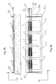
- Fig. 6 and Fig. 7 From Fig. 6 and Fig. 7 are heat sink 15, 16 with a square or with an octagonal cross section visible. On the heat sink 15 with a square cross section are on the Outside surfaces four solid-state laser units 1 is arranged. On the Heatsinks 16 with octagonal cross-section are on the outside eight solid-state laser units 1 arranged. The one from each this solid state laser units 1 emerging laser radiation 14 is parallel to the laser radiation 14 coming from the other Solid-state laser units 1 exits, so that these laser radiation be easily focused in a common focus area can.
- heat sink with others for example, three or five or many Provide geometries such that three, five or a variety of Solid-state laser units 1 arranged on the outer surfaces can be.
- Fig. 8a is another embodiment of a The laser device according to the invention can be seen in which a Heat sink 17 is used, which has a stepped top having.
- the individual stages 18a, 18b, 18c, 18d are each in the Z direction offset against each other.
- a solid-state laser unit 1 is arranged, which, as shown by the arrows 19 is indicated, pumped with corresponding pumping light can be. From each of the solid-state laser units 1 can according to the embodiment according to FIG. 2 and FIG. 3 Laser radiation 14 exit.
- FIGS. 9a and 9b show a further embodiment of a Laser device according to the invention, in which a plurality of Solid state laser units 1 in succession on a heat sink 21st are arranged.
- the heat sink 21 has no on its surface Steps up. Rather, all solid-state laser units are 1 arranged at the same height with respect to the z-direction. To this Way, this occurs in one of the solid-state laser units 1 generated Laser light through the other solid state laser units 1 therethrough.
- those for the individual solid-state laser units 1 provided pump light sources arranged such that the optical pumped channels 4 of the individual solid-state laser units 1 in the x direction essentially aligned with each other.
- FIGS. 9a and 9b an external resonator with one in Fig. 9a and Fig. 9b left shown highly reflective resonator mirror 22 and a in Fig. 9a and Fig. 9b are provided with a right-angled resonator mirror 23 be, which serves as an output coupler. From Fig. 9b is again visible, that the laser radiation 14 emerging from the laser device spaced apart in the y-direction and adjacent to each other arranged partial beams 24 consists.
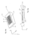
- Fig. 10a and Fig. 10b is another embodiment of a Solid state laser unit 25 according to the invention can be seen.
- These Solid-state laser unit 25 can in particular completely it can be unstructured, that is, it can be made from a laser-active medium such as Nd: YAG exist without any one whatsoever a kind of sandwich structure consisting of active and non-active areas is provided.
- a laser-active medium such as Nd: YAG exist without any one whatsoever a kind of sandwich structure consisting of active and non-active areas is provided.
- 10b are the end-side exit surfaces 26, 27 mirrored, wherein
- the left in Fig. 10b left exit surface 26 high reflective mirrored
- the right in Fig. 10b exit surface 27 is only partially reflecting mirrored, so that this as an output coupler acts.
- the resonator is thus between the exit surfaces 26, 27th formed, wherein at the upper entrance surface 28 for pump radiation the generated laser radiation 29 is also reflected.
- Fig. 10a clearly visible, not up to the front edges of the Solid state laser unit 25 or not to the Exit surfaces 26, 27 adjacent, so that no laser radiation 29th arises, which could leak in the upper edge region 31, 32.
- Fig. 10b is the hatched area, the extension of the pumped channels 30 indicated.
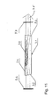
- Fig. 11 is another embodiment of a Solid state laser unit 31 according to the invention can be seen, the also exit surfaces 32, 33, which with the upper Entrance surface 34 include an angle less than 90 °. However, that is the angle in the embodiment according to FIG. 11 is chosen such that that the laser radiation emerging from the exit surfaces 32, 33 35 substantially parallel to the upper entrance surface 34 of the Solid-state laser unit 31 emerges.
- the embodiment according to FIG. 11 shows external resonator mirrors 36, 37, which are shown in FIG for example, as a highly reflective mirror and as an output coupler can be trained. Also in Fig. 11 is in turn by the hatched area the extent of the pumped channels 30th indicated.
- FIGS. 10a and 10b or as shown in FIG. 11 may also instead of Nd: YAG consist of other laser active media, as in the The foregoing has been carried out to the solid-state laser unit 1.
- Solid state laser unit 31 also in the embodiments with a plurality of solid-state laser units according to FIGS. 6, 7, 8a, 8b and according to FIGS. 9 a, 9 b instead of the solid-state laser unit 1 use.
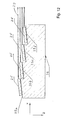
- FIG. 12 is another embodiment of a The laser device according to the invention can be seen in which on the Top of a stepped heat sink 38 solid state laser units 25 according to the embodiment according to FIGS. 10a and 10b are applied.
- the laser device according to FIG. 12 corresponds to FIG Essentially the laser device according to FIGS. 8a and 8b with the Difference that the steps 39 a, 39 b, 39 c, 39 d of the heat sink 38th an angle with the propagation direction (x) of the laser light 29th Include, so that from the individual solid-state laser units 25 emergent partial beams parallel to each other, the laser device leave and above or below the emerging from the other solid-state laser units 25 Partial beams run.
Landscapes
- Physics & Mathematics (AREA)
- Electromagnetism (AREA)
- Engineering & Computer Science (AREA)
- Plasma & Fusion (AREA)
- Optics & Photonics (AREA)
- Lasers (AREA)
Priority Applications (2)
| Application Number | Priority Date | Filing Date | Title |
|---|---|---|---|
| EP03020178A EP1513232A1 (fr) | 2003-09-05 | 2003-09-05 | Dispositif laser et procédé de fonctionnement du dispositif laser |
| PCT/EP2004/009686 WO2005025018A1 (fr) | 2003-09-05 | 2004-08-31 | Dispositif laser et son mode de fonctionnement |
Applications Claiming Priority (1)
| Application Number | Priority Date | Filing Date | Title |
|---|---|---|---|
| EP03020178A EP1513232A1 (fr) | 2003-09-05 | 2003-09-05 | Dispositif laser et procédé de fonctionnement du dispositif laser |
Publications (1)
| Publication Number | Publication Date |
|---|---|
| EP1513232A1 true EP1513232A1 (fr) | 2005-03-09 |
Family
ID=34130152
Family Applications (1)
| Application Number | Title | Priority Date | Filing Date |
|---|---|---|---|
| EP03020178A Withdrawn EP1513232A1 (fr) | 2003-09-05 | 2003-09-05 | Dispositif laser et procédé de fonctionnement du dispositif laser |
Country Status (2)
| Country | Link |
|---|---|
| EP (1) | EP1513232A1 (fr) |
| WO (1) | WO2005025018A1 (fr) |
Citations (5)
| Publication number | Priority date | Publication date | Assignee | Title |
|---|---|---|---|---|
| US5365538A (en) * | 1992-10-29 | 1994-11-15 | The Charles Stark Draper Laboratory Inc. | Slab waveguide pumped channel waveguide laser |
| US5521931A (en) * | 1993-11-22 | 1996-05-28 | Xerox Corporation | Nonmonolithic arrays of accurately positioned diode lasers |
| DE19811211A1 (de) * | 1998-03-10 | 1999-09-16 | Max Born Inst Fuer Nichtlinear | Multipath-Wellenleiter-Festkörperlaser oder -Verstärkeranordnung |
| US5987043A (en) * | 1997-11-12 | 1999-11-16 | Opto Power Corp. | Laser diode arrays with offset components |
| US20020181534A1 (en) * | 2000-10-25 | 2002-12-05 | Spectra-Physics Lasers, Inc. | Diode-pumped slab solid-state laser |
Family Cites Families (3)
| Publication number | Priority date | Publication date | Assignee | Title |
|---|---|---|---|---|
| DE4229498A1 (de) * | 1992-09-04 | 1994-03-10 | Deutsche Aerospace | Festkörperlaser |
| DE4239653C2 (de) * | 1992-11-26 | 1996-11-07 | Daimler Benz Aerospace Ag | Kühlanordnung für ein Festkörperlaserarray |
| US5485482A (en) * | 1993-12-08 | 1996-01-16 | Selker; Mark D. | Method for design and construction of efficient, fundamental transverse mode selected, diode pumped, solid state lasers |
-
2003
- 2003-09-05 EP EP03020178A patent/EP1513232A1/fr not_active Withdrawn
-
2004
- 2004-08-31 WO PCT/EP2004/009686 patent/WO2005025018A1/fr not_active Ceased
Patent Citations (5)
| Publication number | Priority date | Publication date | Assignee | Title |
|---|---|---|---|---|
| US5365538A (en) * | 1992-10-29 | 1994-11-15 | The Charles Stark Draper Laboratory Inc. | Slab waveguide pumped channel waveguide laser |
| US5521931A (en) * | 1993-11-22 | 1996-05-28 | Xerox Corporation | Nonmonolithic arrays of accurately positioned diode lasers |
| US5987043A (en) * | 1997-11-12 | 1999-11-16 | Opto Power Corp. | Laser diode arrays with offset components |
| DE19811211A1 (de) * | 1998-03-10 | 1999-09-16 | Max Born Inst Fuer Nichtlinear | Multipath-Wellenleiter-Festkörperlaser oder -Verstärkeranordnung |
| US20020181534A1 (en) * | 2000-10-25 | 2002-12-05 | Spectra-Physics Lasers, Inc. | Diode-pumped slab solid-state laser |
Also Published As
| Publication number | Publication date |
|---|---|
| WO2005025018A1 (fr) | 2005-03-17 |
Similar Documents
| Publication | Publication Date | Title |
|---|---|---|
| EP1896893B1 (fr) | Dispositif de mise en forme de rayon | |
| DE69631895T2 (de) | Vorrichtung und verfahren zum seitlichen pumpen einer optischen faser | |
| DE102004045912B4 (de) | Verfahren und Vorrichtung zur Überlagerung von Strahlenbündeln | |
| DE102013102880B4 (de) | Laseranordnung | |
| WO2000008726A2 (fr) | Systeme d'amplification laser | |
| EP1502336B1 (fr) | Dispositif laser a semi-conducteur a pompage optique | |
| EP2917985B1 (fr) | Amplificateur optique slab à pompage par extrémité avec modules de pompage distribués | |
| DE19813127A1 (de) | Laservorrichtung | |
| DE102004053137A1 (de) | Multispektraler Laser mit mehreren Gainelementen | |
| DE4101403C2 (de) | Halbleiterlaser-gepumpter Festkörperlaser | |
| DE112019003882T5 (de) | Lasersystem mit treppenförmig angeordneten slow-axis-kollimatoren | |
| WO2018141670A1 (fr) | Dispositif de collimation d'un faisceau lumineux, laser haute puissance et optique de focalisation ainsi que procédé de collimation d'un faisceau lumineux | |
| DE10204246B4 (de) | Festkörper-Laserverstärkersystem | |
| DE102006039074B4 (de) | Optische Anordnung zum Pumpen von Festkörperlasern | |
| DE10296788B4 (de) | Laserpumpverfahren | |
| EP1629576B1 (fr) | Procede et dispositif pour pomper un laser | |
| EP0903823A2 (fr) | Elément laser comprenant un réseau à laser et méthode de fabrication | |
| EP1513232A1 (fr) | Dispositif laser et procédé de fonctionnement du dispositif laser | |
| DE102013102891B4 (de) | Laseranordnung | |
| DE602006000447T2 (de) | System zum optischen Pumpen einer Laserquelle und Laserquelle welche dieses optische Pumpsystem verwendet | |
| DE102004045914B4 (de) | Verfahren und Vorrichtung zur Überlagerung von Strahlenbündeln | |
| DE602004003743T2 (de) | Faserlaser und Verfahren zu dessen Betrieb | |
| DE102020109422B4 (de) | Transformationsvorrichtung für Laserstrahlung und Laservorrichtung | |
| DE102019123533B4 (de) | Lasersystem und Verfahren zum Betreiben eines Lasersystems | |
| DE102004012307A1 (de) | Festkörperlaser |
Legal Events
| Date | Code | Title | Description |
|---|---|---|---|
| PUAI | Public reference made under article 153(3) epc to a published international application that has entered the european phase |
Free format text: ORIGINAL CODE: 0009012 |
|
| 17P | Request for examination filed |
Effective date: 20040227 |
|
| AK | Designated contracting states |
Kind code of ref document: A1 Designated state(s): AT BE BG CH CY CZ DE DK EE ES FI FR GB GR HU IE IT LI LU MC NL PT RO SE SI SK TR |
|
| AX | Request for extension of the european patent |
Extension state: AL LT LV MK |
|
| GRAP | Despatch of communication of intention to grant a patent |
Free format text: ORIGINAL CODE: EPIDOSNIGR1 |
|
| AKX | Designation fees paid | ||
| REG | Reference to a national code |
Ref country code: DE Ref legal event code: 8566 |
|
| STAA | Information on the status of an ep patent application or granted ep patent |
Free format text: STATUS: THE APPLICATION IS DEEMED TO BE WITHDRAWN |
|
| 18D | Application deemed to be withdrawn |
Effective date: 20050924 |