EP1513212B1 - Festpolymerelektrolytmenbran und Brennstofzelle - Google Patents
Festpolymerelektrolytmenbran und Brennstofzelle Download PDFInfo
- Publication number
- EP1513212B1 EP1513212B1 EP04254731A EP04254731A EP1513212B1 EP 1513212 B1 EP1513212 B1 EP 1513212B1 EP 04254731 A EP04254731 A EP 04254731A EP 04254731 A EP04254731 A EP 04254731A EP 1513212 B1 EP1513212 B1 EP 1513212B1
- Authority
- EP
- European Patent Office
- Prior art keywords
- polymer electrolyte
- solid polymer
- electrolyte membrane
- silica
- ion exchange
- Prior art date
- Legal status (The legal status is an assumption and is not a legal conclusion. Google has not performed a legal analysis and makes no representation as to the accuracy of the status listed.)
- Expired - Lifetime
Links
Images



Classifications
-
- C—CHEMISTRY; METALLURGY
- C08—ORGANIC MACROMOLECULAR COMPOUNDS; THEIR PREPARATION OR CHEMICAL WORKING-UP; COMPOSITIONS BASED THEREON
- C08J—WORKING-UP; GENERAL PROCESSES OF COMPOUNDING; AFTER-TREATMENT NOT COVERED BY SUBCLASSES C08B, C08C, C08F, C08G or C08H
- C08J5/00—Manufacture of articles or shaped materials containing macromolecular substances
- C08J5/20—Manufacture of shaped structures of ion-exchange resins
- C08J5/22—Films, membranes or diaphragms
- C08J5/2206—Films, membranes or diaphragms based on organic and/or inorganic macromolecular compounds
- C08J5/2275—Heterogeneous membranes
- C08J5/2281—Heterogeneous membranes fluorine containing heterogeneous membranes
-
- H—ELECTRICITY
- H01—ELECTRIC ELEMENTS
- H01B—CABLES; CONDUCTORS; INSULATORS; SELECTION OF MATERIALS FOR THEIR CONDUCTIVE, INSULATING OR DIELECTRIC PROPERTIES
- H01B1/00—Conductors or conductive bodies characterised by the conductive materials; Selection of materials as conductors
- H01B1/06—Conductors or conductive bodies characterised by the conductive materials; Selection of materials as conductors mainly consisting of other non-metallic substances
- H01B1/12—Conductors or conductive bodies characterised by the conductive materials; Selection of materials as conductors mainly consisting of other non-metallic substances organic substances
- H01B1/122—Ionic conductors
-
- H—ELECTRICITY
- H01—ELECTRIC ELEMENTS
- H01M—PROCESSES OR MEANS, e.g. BATTERIES, FOR THE DIRECT CONVERSION OF CHEMICAL ENERGY INTO ELECTRICAL ENERGY
- H01M8/00—Fuel cells; Manufacture thereof
- H01M8/10—Fuel cells with solid electrolytes
- H01M8/1016—Fuel cells with solid electrolytes characterised by the electrolyte material
- H01M8/1018—Polymeric electrolyte materials
- H01M8/102—Polymeric electrolyte materials characterised by the chemical structure of the main chain of the ion-conducting polymer
- H01M8/1023—Polymeric electrolyte materials characterised by the chemical structure of the main chain of the ion-conducting polymer having only carbon, e.g. polyarylenes, polystyrenes or polybutadiene-styrenes
-
- H—ELECTRICITY
- H01—ELECTRIC ELEMENTS
- H01M—PROCESSES OR MEANS, e.g. BATTERIES, FOR THE DIRECT CONVERSION OF CHEMICAL ENERGY INTO ELECTRICAL ENERGY
- H01M8/00—Fuel cells; Manufacture thereof
- H01M8/10—Fuel cells with solid electrolytes
- H01M8/1016—Fuel cells with solid electrolytes characterised by the electrolyte material
- H01M8/1018—Polymeric electrolyte materials
- H01M8/102—Polymeric electrolyte materials characterised by the chemical structure of the main chain of the ion-conducting polymer
- H01M8/1025—Polymeric electrolyte materials characterised by the chemical structure of the main chain of the ion-conducting polymer having only carbon and oxygen, e.g. polyethers, sulfonated polyetheretherketones [S-PEEK], sulfonated polysaccharides, sulfonated celluloses or sulfonated polyesters
-
- H—ELECTRICITY
- H01—ELECTRIC ELEMENTS
- H01M—PROCESSES OR MEANS, e.g. BATTERIES, FOR THE DIRECT CONVERSION OF CHEMICAL ENERGY INTO ELECTRICAL ENERGY
- H01M8/00—Fuel cells; Manufacture thereof
- H01M8/10—Fuel cells with solid electrolytes
- H01M8/1016—Fuel cells with solid electrolytes characterised by the electrolyte material
- H01M8/1018—Polymeric electrolyte materials
- H01M8/1039—Polymeric electrolyte materials halogenated, e.g. sulfonated polyvinylidene fluorides
-
- H—ELECTRICITY
- H01—ELECTRIC ELEMENTS
- H01M—PROCESSES OR MEANS, e.g. BATTERIES, FOR THE DIRECT CONVERSION OF CHEMICAL ENERGY INTO ELECTRICAL ENERGY
- H01M8/00—Fuel cells; Manufacture thereof
- H01M8/10—Fuel cells with solid electrolytes
- H01M8/1016—Fuel cells with solid electrolytes characterised by the electrolyte material
- H01M8/1018—Polymeric electrolyte materials
- H01M8/1041—Polymer electrolyte composites, mixtures or blends
- H01M8/1046—Mixtures of at least one polymer and at least one additive
- H01M8/1051—Non-ion-conducting additives, e.g. stabilisers, SiO2 or ZrO2
-
- H—ELECTRICITY
- H01—ELECTRIC ELEMENTS
- H01M—PROCESSES OR MEANS, e.g. BATTERIES, FOR THE DIRECT CONVERSION OF CHEMICAL ENERGY INTO ELECTRICAL ENERGY
- H01M8/00—Fuel cells; Manufacture thereof
- H01M8/10—Fuel cells with solid electrolytes
- H01M8/1016—Fuel cells with solid electrolytes characterised by the electrolyte material
- H01M8/1018—Polymeric electrolyte materials
- H01M8/1041—Polymer electrolyte composites, mixtures or blends
- H01M8/1053—Polymer electrolyte composites, mixtures or blends consisting of layers of polymers with at least one layer being ionically conductive
-
- H—ELECTRICITY
- H01—ELECTRIC ELEMENTS
- H01M—PROCESSES OR MEANS, e.g. BATTERIES, FOR THE DIRECT CONVERSION OF CHEMICAL ENERGY INTO ELECTRICAL ENERGY
- H01M8/00—Fuel cells; Manufacture thereof
- H01M8/10—Fuel cells with solid electrolytes
- H01M8/1016—Fuel cells with solid electrolytes characterised by the electrolyte material
- H01M8/1018—Polymeric electrolyte materials
- H01M8/1058—Polymeric electrolyte materials characterised by a porous support having no ion-conducting properties
- H01M8/106—Polymeric electrolyte materials characterised by a porous support having no ion-conducting properties characterised by the chemical composition of the porous support
-
- C—CHEMISTRY; METALLURGY
- C08—ORGANIC MACROMOLECULAR COMPOUNDS; THEIR PREPARATION OR CHEMICAL WORKING-UP; COMPOSITIONS BASED THEREON
- C08J—WORKING-UP; GENERAL PROCESSES OF COMPOUNDING; AFTER-TREATMENT NOT COVERED BY SUBCLASSES C08B, C08C, C08F, C08G or C08H
- C08J2327/00—Characterised by the use of homopolymers or copolymers of compounds having one or more unsaturated aliphatic radicals, each having only one carbon-to-carbon double bond, and at least one being terminated by a halogen; Derivatives of such polymers
- C08J2327/02—Characterised by the use of homopolymers or copolymers of compounds having one or more unsaturated aliphatic radicals, each having only one carbon-to-carbon double bond, and at least one being terminated by a halogen; Derivatives of such polymers not modified by chemical after-treatment
- C08J2327/12—Characterised by the use of homopolymers or copolymers of compounds having one or more unsaturated aliphatic radicals, each having only one carbon-to-carbon double bond, and at least one being terminated by a halogen; Derivatives of such polymers not modified by chemical after-treatment containing fluorine atoms
- C08J2327/18—Homopolymers or copolymers of tetrafluoroethylene
-
- C—CHEMISTRY; METALLURGY
- C08—ORGANIC MACROMOLECULAR COMPOUNDS; THEIR PREPARATION OR CHEMICAL WORKING-UP; COMPOSITIONS BASED THEREON
- C08J—WORKING-UP; GENERAL PROCESSES OF COMPOUNDING; AFTER-TREATMENT NOT COVERED BY SUBCLASSES C08B, C08C, C08F, C08G or C08H
- C08J2383/00—Characterised by the use of macromolecular compounds obtained by reactions forming in the main chain of the macromolecule a linkage containing silicon with or without sulfur, nitrogen, oxygen, or carbon only; Derivatives of such polymers
- C08J2383/02—Polysilicates
-
- Y—GENERAL TAGGING OF NEW TECHNOLOGICAL DEVELOPMENTS; GENERAL TAGGING OF CROSS-SECTIONAL TECHNOLOGIES SPANNING OVER SEVERAL SECTIONS OF THE IPC; TECHNICAL SUBJECTS COVERED BY FORMER USPC CROSS-REFERENCE ART COLLECTIONS [XRACs] AND DIGESTS
- Y02—TECHNOLOGIES OR APPLICATIONS FOR MITIGATION OR ADAPTATION AGAINST CLIMATE CHANGE
- Y02E—REDUCTION OF GREENHOUSE GAS [GHG] EMISSIONS, RELATED TO ENERGY GENERATION, TRANSMISSION OR DISTRIBUTION
- Y02E60/00—Enabling technologies; Technologies with a potential or indirect contribution to GHG emissions mitigation
- Y02E60/30—Hydrogen technology
- Y02E60/50—Fuel cells
Definitions
- the present invention relates to a solid polymer electrolyte membrane for manufacturing an electrochemical cell used in a solid polymer electrolyte fuel cell or the like, and relates to a fuel cell that uses this solid polymer electrolyte membrane.
- Fuel cells are classified as phosphoric acid type, molten carbonate type, solid oxide type, solid polymer electrolyte type, and other types according to the type of electrolyte.
- solid polymer electrolyte fuel cells use an ion exchange resin that is a solid polymer electrolyte membrane as the electrolyte, have electrodes joined to both sides of the membrane, and have such main advantages as the following:
- styrene-divinylbenzene ion exchange resins in which an ion exchange group is introduced to a styrene-divinylbenzene resin parent nucleus
- a styrene-divinylbenzene ion exchange resin is physically or chemically unstable with respect to the electrochemical effects or reactions occurring on the surface or in the interior of the solid polymer electrolyte membrane surface of a fuel cell, so a long service life for the cell cannot be obtained.
- a solid polymer electrolyte membrane is also usually heated/hydrated when used as a fuel cell, and compression force is applied thereon in the membrane thickness direction. If the solid polymer electrolyte membrane has low mechanical strength, the membrane deforms and becomes thinner due to swelling, creeping, or the like. As a result, gas crossover occurs, and electrolyte performance declines.
- silica particles yields adequate membrane reinforcing effects but produces enhanced electrical resistance when the particles are large.
- Using small particles reduces the electrical resistance but fails to deliver adequate membrane reinforcing effects. It is thus difficult to ensure both positive effects at the same time.
- WO 00/23510 proposes a solid polymer electrolyte membrane comprising an ion exchange resin wherein chopped silica fibers and silica micro fibers are dispersed with the objective of improving dimensional stability without compromising the ionic conductivity and reactant gas cross-over parameters.
- the present invention was developed in view of such drawbacks as the foregoing, and an object thereof is to provide a solid polymer electrolyte membrane in which both the mechanical strength (resistance to membrane thinning, durability against gas permeation, and the like) and electrical resistance are improved, and also to provide a fuel cell that uses this solid polymer electrolyte membrane.
- the solid polymer electrolyte membrane (membrane composed of at least an ion exchange resin) pertaining to the present invention has as its main characteristic that beaded silica is dispersed therein.
- the ratio of the ion exchange resin and the beaded silica may be about 1 to 50 wt%, for example.
- the beaded silica preferably has a primary particle size of 50 nm or less as measured with the help of the BET method, and a particle size of 60 nm or more as measured with the help of dynamic light scattering.
- the solid polymer electrolyte membrane preferably contains a reinforcing material, and the reinforcing material is preferably a porous resin sheet.
- the ion exchange resin and the beaded silica are included in the pores in the resin sheet.
- the porous resin sheet is preferably a porous polytetrafluoroethylene resin membrane.
- the solid polymer electrolyte membrane of the present invention preferably has an ion exchange resin layer formed on the surface thereof. The effects of using beaded silica are prominent when the thickness of the solid polymer electrolyte membrane is 60 ⁇ m or less.
- a fuel cell provided with the above-mentioned solid polymer electrolyte membrane is also included in the present invention.
- the solid polymer electrolyte membrane of the present invention is characterized in that beaded silica is dispersed (included) therein.
- beaded silica is useful for improving electrical resistance but is incapable of improving mechanical strength
- large-grained silica is useful for improving mechanical strength but is incapable of improving electrical resistance
- beaded silica is capable of improving both electrical resistance and mechanical strength.
- the aforementioned beaded silica is obtained as a result of the coupling of a plurality of substantially spherical silica particles.
- the beaded silica is commercially available from Nissan Chemical Industries (Ltd.) and the like, and the details thereof are described in JP (Kokai) No. H1-317115, H7-118008, and other publications. The characteristics of the beaded silica from these publications are summarized below.
- the beaded silica is prepared as colloidal silica.
- the particle size D 1 is about 40 to 500 nm (about 80 to 150 nm in the commercial product).
- the ratio of the particle size D 1 and the particle size D2 indicates the degree of extension of the beaded silica, and is about 5 to 30. According to observation with the help of an electron microscope, the product has a uniform size of about 5 to 40 nm and has extension in one plane only. However, this does not mean that the extension is purely in the same plane in a strictly mathematical sense, but that the properties of silica sols having a three-dimensional mesh structure or a similar structure are not demonstrated.
- This beaded silica is commercially available under the product name "SNO-TEX PS” from Nissan Chemical Industries (Ltd.), and it is preferred to use this product.
- the primary particle size (particle size as measured with the help of the BET method) of the beaded silica determines the electrical resistance of the solid polymer electrolyte membrane, and the particle size as measured with the help of dynamic light scattering determines the mechanical strength (resistance to membrane thinning, durability against gas permeation, and the like) of the solid polymer electrolyte membrane.
- beaded silica that has a primary particle size (as measured with the help of the BET method) of the same value as small-grained spherical silica can be equated with small-grained spherical silica from the perspective of electrical resistance
- beaded silica whose particle size (as measured with the help of dynamic light scattering) has the same value as the primary particle size (as measured with the help of the BET method) of large-grained spherical silica can be equated with large-grained spherical silica from the perspective of mechanical strength (resistance to membrane thinning, durability against gas permeation, and the like).
- the primary particle size and the particle size as measured with the help of dynamic light scattering of the beaded silica should therefore be selected with consideration of the primary particle sizes of the small-grained spherical silica and the large-grained spherical silica in order to use both the excellent low electrical resistance obtained when the small-grained spherical silica is used and the excellent mechanical strength obtained when the large-grained spherical silica is used to improve the solid polymer electrolyte membrane.
- a beaded silica that has a primary particle size of about 50 nm or less, for example, (preferably 40 nm or less, and more preferably 30 nm or less) and a particle size according to dynamic light scattering of about 60 nm or more, for example, (preferably 70 nm or more, and more preferably 80 nm or more).
- the minimum primary particle size is about 10 nm if it is assumed that the above-mentioned "SNO-TEX PS" is used, but a smaller product is preferably used as smaller-grained products become commercially available in the future, and the minimum size is not particularly limited.
- the maximum particle size according to dynamic light scattering is also about 150 nm if it is assumed that the above-mentioned "SNO-TEX PS" is used, but a larger product is preferably used as larger-grained products become commercially available in the future, and the maximum size is not particularly limited.
- the beaded silica may be appropriately combined with spherical silica (small-grained spherical silica, large-grained spherical silica, and the like) as needed, and the electrolyte membrane improvement characteristics thereof may be finely adjusted accordingly.
- spherical silica small-grained spherical silica, large-grained spherical silica, and the like
- the admixed quantity of the beaded silica can be appropriately set according to the type, ratio, desired properties, and other attributes of the ion exchange resin used as the solid polymer electrolyte membrane; the porous resin sheet (described in detail hereinafter) that can be used together with the ion exchange resin; and the like.
- the admixed quantity of beaded silica may be set such that the ratio of the ion exchange resin and the beaded silica (beaded silica/ion exchange resin) ranges from about 1 wt% or higher (preferably 3 wt% or higher, and more preferably 5 wt% or higher) to 50 wt% or lower (preferably 30 wt% or lower, and more preferably 20 wt% or lower).
- the solid polymer electrolyte membrane that is the subject of the present invention is not particularly limited insofar as it is a polymer membrane that can contain beaded silica. This is because an object of the present invention is to modify a solid polymer electrolyte membrane by means of beaded silica as described above. Specifically, the solid polymer electrolyte membrane is not particularly limited insofar as it is composed of at least an ion exchange resin.
- the solid polymer electrolyte membrane is generally used in a sheeted form, but a cylindrical form thereof may also be used.
- an electrode layer is formed on the external surface and the internal surface of the cylinder.
- a reinforcing material can be contained in the membrane of the solid polymer electrolyte membrane of the present invention.
- Reinforcing materials other than the porous resin sheet described hereinafter include fibrous substances.
- Preferred materials made from fibrous substances include various fluororesin fibers, glass fibers, or other materials that possess chemical resistant properties.
- the fibers are preferably as thin as possible, with a diameter of 0.3 ⁇ m or less, for example, and fibers can be used that have a length of several hundred micrometers to several micrometers. This type of fibrous substance is preferably used in an evenly dispersed state in the solid polymer electrolyte membrane.
- the preferred solid polymer electrolyte membrane includes a membrane in which an ion exchange resin is reinforced with the help of a porous resin sheet. When a porous resin sheet is used, the beaded silica and the ion exchange resin are contained in the pores.
- the preferred solid polymer electrolyte membrane includes one in which one of either (or both) the ion exchange resin or the porous resin sheet that may be used together with this ion exchange resin is formed from fluororesin. Durability (physical durability and chemical durability), mechanical strength, and the like can be further improved if these preferred solid polymer electrolyte membranes are used.
- Ion exchange resins can be classified into non-fluororesin-type ion exchange resins and fluororesin-type ion exchange resins.
- Non-fluororesin-type ion exchange resins include polyalkylene oxides, polyvinyl alcohols, styrene-divinylbenzene ion exchange resins, and the like, and these may also form metallic salts.
- Preferred non-fluororesin-type ion exchange resins include polyalkylene oxide-alkali metal salt complexes (obtained as a result of polymerizing an ethylene oxide oligomer in the presence of lithium chlorate or another alkali metal salt, for example).
- Fluororesin-type ion exchange resins include perfluorosulfonic acid resins, perfluorocarboxylic acid resins, and the like.
- the preferred fluororesin-type ion exchange resin is a perfluorocarboxylic acid resin.
- Perfluorocarboxylic acid resins are commercially available under the product names "Nafion” (Du Pont Inc.), "Aciplex” (Asahi Kasei (Inc.)), “Flemion” (Asahi Gas (Ltd,)), and the like, and these products may be used.
- a woven cloth or nonwoven cloth formed from a polymer fiber or polymer staple fiber may be used as the porous resin sheet, and a porous resin sheet may be used.
- the porous resin sheet may be manufactured by means of expanding a resin and forming continuous voids, for example, and may also be manufactured as a result of eluting the island portions of a resin with a sea-island structure that has continuous island portions.
- a porous structure may also be formed by means of stretching.
- These porous resin sheets may be non-fluororesins or fluororesins.
- porous polytetrafluoroethylene (PTFE) resin sheet can be used appropriately as the porous resin.
- the porous polytetrafluoroethylene resin sheet can be manufactured by means of stretching a paste-extruded PTFE resin sheet. The details of this process are disclosed, for example, in JP (Kokoku) No. S51-18991 . The stretching may be uniaxial or biaxial.
- a uniaxially stretched porous PTFE resin is characterized in that narrow island-shaped nodes (folded crystals) that are substantially orthogonal to the stretching direction are present therein on a microscopic level, and that a lattice of fibrils (linear molecular bundles obtained by means of the stretching-induced melting and drawing of folded crystals) is oriented in the stretching direction so as to link the nodes.
- a biaxially stretched porous PTFE resin is characterized on the microscopic level in that the fibrils are spread out in radial fashion, the nodes connecting the fibrils are scattered in island fashion, and a fibrous structure is formed with a spider web pattern in which there are numerous spaces formed by the fibrils and nodes.
- This type of porous PTFE resin sheet is commercially available under the product name "Gore-Tex" (Japan Gore-Tex (Ltd.)), and this product may be used.
- a particularly preferred solid polymer electrolyte membrane includes one in which an ion exchange resin (fluorinated or non-fluorinated ion exchange resin) is reinforced with the help of a porous fluororesin sheet (porous PTFE resin sheet).
- a porous PTFE resin sheet is combined with an ion exchange resin, the void content of the porous PTFE resin sheet can be appropriately adjusted according to the draw ratio and the like, and is about 30% or higher (preferably 50% or higher, and more preferably 70% or higher) and 95% or lower (preferably 93% or lower, and more preferably 90% or lower), for example.
- the average pore diameter of the porous PTFE resin sheet can also be appropriately adjusted according to the draw ratio and the like, and is about 0.05 to 5 ⁇ m, preferably 0.5 to 1 ⁇ m, for example.
- Void content % 1 - D / D standard ⁇ 100
- the average pore diameter can also be measured using a Coulter Porometer manufactured by Coulter Electronics.
- the ratio of the porous PTFE resin sheet and the ion exchange resin can be appropriately adjusted according to the desired properties.
- the ratio of the porous PTFE resin sheet and the ion exchange resin may be selected from the range of about 5/95 to 50/50 (weight ratio), preferably about 10/90 to 30/70 (weight ratio), and more preferably about 15/85 to 25/75 (weight ratio), for example.
- the thickness of the solid polymer electrolyte membrane is not particularly limited, and may be 60 ⁇ m or less (particularly about 50 ⁇ m or less), for example. This is because the lower the membrane thickness, the more likely it is for the mechanical strength to decrease, so mechanical strength improvement effects by means of beaded silica are earnestly pursued.
- the thickness of the solid polymer electrolyte membrane is usually about 5 ⁇ m or more (10 ⁇ m or more, and particularly 20 ⁇ m or more, for example).
- the solid polymer electrolyte membrane is also not limited to the above-mentioned base portion (ion exchange resin, beaded silica, and optional porous resin sheet), and an ion exchange resin layer (layer composed of a second ion exchange resin) may also be formed on the surface thereof, for example.
- This ion exchange resin layer preferably contains no silica or other inorganic particles, and is useful for increasing the surface smoothness of the solid polymer electrolyte membrane and enhancing the bond between the electrolyte membrane and the electrode.
- the second ion exchange resin that constitutes the ion exchange resin layer may be selected from the same range as the ion exchange resin that may be used in the aforementioned base portion.
- the type of second ion exchange resin is preferably paired with the type of ion exchange resin used in the base portion.
- the thickness of the ion exchange resin layer is about 1 to 10 ⁇ m, preferably about 3 to 7 ⁇ m, and more preferably about 4 to 6 ⁇ m, for example.
- the solid polymer electrolyte membrane may also contain various components as needed; for example, Pt or the like.
- the solid polymer electrolyte membrane of the present invention contains beaded silica, so the electrical resistance thereof is reduced, and the mechanical strength is increased. It is therefore suited for use in a fuel cell, a sensor, an ozone generating device, a device for generating hydrogen or oxygen by way of electrolysis, a separator for an electrochemical device that involves proton movement, a dehumidifying membrane, a humidifying membrane, and the like in the same manner as a conventional, publicly known solid polymer electrolyte film.
- colloidal silica shown in Table 1 below was added to an ion exchange resin solution (solvent: mixture of 1-propanol and water; resin: perfluorosulfonic acid (Du Pont "Nafion”); concentration: 15 wt%) to give a silica (solid content)/ion exchange resin (solid content) ratio of 10 wt%, and the ingredients were thoroughly stirred/dispersed.
- a stretched porous PTFE resin sheet with a membrane thickness of 20 ⁇ m, a void content of 80% by volume, and an average pore diameter of 0.5 ⁇ m (product name: "Gore-Tex”; manufactured by Japan Gore-Tex Inc.) was impregnated with the above-mentioned silica-dispersed ion exchange resin solution, the product was placed in an oven at a temperature of 100°C, and the solvent was evaporated.
- the ion exchange resin solution described above before addition of the colloidal silica was applied again onto both sides of the resultant membrane, the product was placed in an oven at a temperature of 100°C, and the solvent was evaporated, whereby a solid polymer electrolyte membrane was obtained.
- This solid polymer electrolyte membrane had an overall thickness of 30 ⁇ m, the thickness of the ion exchange resin layer on the surface thereof was 5 ⁇ m, the ratio of the ion exchange resin and the silica (silica/ion exchange resin) was 10 wt%, and the ratio of the porous PTFE resin and the ion exchange resin (porous PTFE resin/ion exchange resin) was 15/85 (weight ratio).
- FIGS. 3 through 6 Electron micrographs of the colloidal silica used and the resultant solid polymer electrolyte membranes are shown in FIGS. 3 through 6 .
- FIG. 3 shows small-grained colloidal silica
- FIG. 4 shows the solid polymer electrolyte membrane manufactured using this small-grained colloidal silica.
- FIG. 5 shows beaded colloidal silica
- FIG. 6 shows the solid polymer electrolyte membrane manufactured using this beaded colloidal silica.
- the beaded colloidal silica clearly differs in structure from usual colloidal silica, and is specifically characterized in that a plurality of silica particles A is connected via the connecting portions B, as is apparent from FIG. 6 .
- the aforementioned connecting portions B are not present in normal colloidal silica, as is apparent from FIG. 4 .
- a gas diffusion electrode (“PRIMEATM 5510,” manufactured by Japan Gore-Tex (Inc.)) was bonded to both sides of the solid polymer electrolyte membrane, and a membrane/electrode assembly (MEA) was fabricated.
- MEA membrane/electrode assembly
- a cell unit for a fuel cell was assembled using this MEA in accordance with the usual method, humidified hydrogen (dew point: 60°C) was fed to one side of the cell, humidified air (dew point: 60°C) was fed to the other side, and the cell was operated at a temperature of 85°C and a gas usage rate of 80% hydrogen and 40% oxygen.
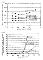
- the current was varied by means of changing the amount of resistance of the load device, and the electrical resistance of the cell at that time was measured with the help of the current interrupt method.
- a cell unit for a fuel cell was assembled in the same manner as described above, humidified hydrogen (dew point: 83°C) was fed to one surface of the cell, air (dew point: 83°C) was fed to the other side, the cell was continuously operated at a gas usage rate of 83% hydrogen and 50% oxygen, a cell temperature of 90°C, an operating current density of 0.8 A/cm 2 , and a gas pressure of 0.1 MPa.
- the air and gas were supplied to both electrodes until operation was no longer possible, and the change in current density due to reaction of H 2 that had crossed over to the cathode was measured. This increase in current density indicates an increased quantity of hydrogen gas transmitted to the negative electrode side.
- Table 2 The results are shown in Table 2 and in FIGS. 1 and 2 .
- Table 2 Working Example Silica name Film thinning resistance properties Cell electrical resistance ( ⁇ ⁇ cm 2 ) Durability against hydrogen gas permeation Percentage of dimensional change (%) Relative value (%) Evaluation Measured result Evaluation Operating time at which current density due to reaction of H 2 crossed-over to the cathode exceeded 10 mA/cm 2 Operable time Evaluation 1 No silica added 8.6 100 Fail 0.17 to 0.20 pass Approx. 600 hr Approx. 700 hr fail 2 Small-grained spherical silica 8.7 101 Fail 0.22 to 0.24 pass Approx. 600 hr Approx.
- the electrical resistance increases when large-grained spherical silica with a large primary particle size is used.
- the electrical resistance can be kept low when small-grained silica or beaded silica with a small primary particle size is used.
- the particle size of beaded silica is equivalent to that of large-grained silica when measured with the help of dynamic light scattering, but the electrical resistance is kept as low as with small-grained silica. It is apparent from these results that the electrical resistance is determined by the primary particle size of the beaded silica, and that the magnitude of the resistance is equivalent to that of small-grained silica with the same primary particle size.
- the mechanical strength (resistance to membrane thinning and durability against hydrogen gas permeation) is reduced when small-grained spherical silica with a small primary particle size is used.
- the mechanical strength increases when large-grained silica or beaded silica with a large primary particle size is used.
- the particle size of beaded silica is equivalent to that of small-grained silica when compared on the basis of primary particle size, but the mechanical strength is as good as with large-grained silica.
Landscapes
- Chemical & Material Sciences (AREA)
- Engineering & Computer Science (AREA)
- Manufacturing & Machinery (AREA)
- General Chemical & Material Sciences (AREA)
- Chemical Kinetics & Catalysis (AREA)
- Sustainable Development (AREA)
- Sustainable Energy (AREA)
- Life Sciences & Earth Sciences (AREA)
- Electrochemistry (AREA)
- Crystallography & Structural Chemistry (AREA)
- Composite Materials (AREA)
- Materials Engineering (AREA)
- Spectroscopy & Molecular Physics (AREA)
- Inorganic Chemistry (AREA)
- Physics & Mathematics (AREA)
- Health & Medical Sciences (AREA)
- Medicinal Chemistry (AREA)
- Polymers & Plastics (AREA)
- Organic Chemistry (AREA)
- Fuel Cell (AREA)
- Conductive Materials (AREA)
- Manufacture Of Macromolecular Shaped Articles (AREA)
- Compositions Of Macromolecular Compounds (AREA)
Claims (8)
- Festpolymerelektrolytmembran, umfassend mindestens ein Ionenaustauschharz; wobei die Festpolymerelektrolytmembran dadurch gekennzeichnet ist, daß perlenförmiges Siliciumdioxid in der Festpolymerelektrolytmembran dispergiert ist, wobei das perlenförmige Siliciumdioxid, wenn in der Form von kolloidalem Siliciumdioxid, eine primäre Teilchengröße von 50 nm oder weniger, wie gemessen durch das BET-Verfahren, und eine Teilchengröße von 60 nm oder mehr, wie gemessen durch dynamische Lichtstreuung, hat.
- Polymerelektrolytmembran gemäß Anspruch 1, wobei das Verhältnis von dem Ionenaustauschharz und dem perlenförmigen Siliciumdioxid (perlenförmiges Siliciumdioxid/Ionenaustauschharz) 1 bis 50 Gew.-% beträgt.
- Festpolymerelektrolytmembran gemäß den Ansprüchen 1 oder 2, wobei die Festpolymerelektrolytmembran ein verstärkendes Material umfaßt.
- Festpolymerelektrolytmembran gemäß Anspruch 3, wobei das verstärkende Material ein poröses Harzflächengebilde umfaßt und das Ionenaustauschharz und das perlenförmige Siliciumdioxid in die Poren in dem Hanflächengebilde eingeschlossen sind.
- Festpolymerelektrolymembran gemäß Anspruch 4, wobei das poröse Harzflächengebilde ein poröses Polytetrafluorethylenharzflächengebilde umfaßt.
- Festpolymerelektrolytmembran gemäß einem der Ansprüche 1 bis 5, weiterhin umfassend eine Ionenaustauschlsarcschicht, erzeugt auf der Oberfläche davon.
- Festpolymerelektrolytmembran gemäß einem der Ansprüche 1 bis 6, wobei die Dicke der Festpolymerelektrolytmembran 60 µm oder weniger beträgt.
- Brennstoffzelle, umfassend die Festpolymerelektrolytmembran gemäß einem der Ansprüche 1 bis 7.
Applications Claiming Priority (2)
| Application Number | Priority Date | Filing Date | Title |
|---|---|---|---|
| JP2003288854A JP4198009B2 (ja) | 2003-08-07 | 2003-08-07 | 固体高分子電解質膜及び燃料電池 |
| JP2003288854 | 2003-08-07 |
Publications (3)
| Publication Number | Publication Date |
|---|---|
| EP1513212A2 EP1513212A2 (de) | 2005-03-09 |
| EP1513212A3 EP1513212A3 (de) | 2006-05-31 |
| EP1513212B1 true EP1513212B1 (de) | 2009-05-20 |
Family
ID=34114057
Family Applications (1)
| Application Number | Title | Priority Date | Filing Date |
|---|---|---|---|
| EP04254731A Expired - Lifetime EP1513212B1 (de) | 2003-08-07 | 2004-08-06 | Festpolymerelektrolytmenbran und Brennstofzelle |
Country Status (5)
| Country | Link |
|---|---|
| US (1) | US20050031929A1 (de) |
| EP (1) | EP1513212B1 (de) |
| JP (1) | JP4198009B2 (de) |
| AT (1) | ATE431971T1 (de) |
| DE (1) | DE602004021160D1 (de) |
Families Citing this family (17)
| Publication number | Priority date | Publication date | Assignee | Title |
|---|---|---|---|---|
| KR100684787B1 (ko) * | 2005-03-31 | 2007-02-20 | 삼성에스디아이 주식회사 | 연료전지용 고분자 전해질막, 이의 제조 방법 및 이를포함하는 연료전지용 스택 및 연료전지 시스템 |
| JP4682358B2 (ja) | 2005-04-05 | 2011-05-11 | 独立行政法人 日本原子力研究開発機構 | 機能性無機/グラフト高分子ハイブリッドイオン交換膜の製造方法および燃料電池用電解質膜 |
| KR101223559B1 (ko) | 2005-06-24 | 2013-01-22 | 삼성에스디아이 주식회사 | 연료 전지용 고분자 전해질 막의 제조 방법 |
| JP5011567B2 (ja) | 2005-11-17 | 2012-08-29 | 独立行政法人日本原子力研究開発機構 | ナノ無機粒子複合橋架け高分子電解質膜及びその製造方法、ならびにそれを用いた膜・電極接合体 |
| EP1972024B1 (de) * | 2005-12-22 | 2012-12-19 | E.I. Du Pont De Nemours And Company | Anorganische füllstoffe enthaltende chemisch stabilisierte ionomere |
| JP4997625B2 (ja) | 2006-03-24 | 2012-08-08 | 独立行政法人日本原子力研究開発機構 | 燃料電池用高分子電解質膜の製造方法、その電解質膜、およびその膜を使用した燃料電池用膜電極接合体 |
| US20070295021A1 (en) * | 2006-06-20 | 2007-12-27 | Albonia Innovative Technologies Ltd. | Apparatus and Method For Generating Water From an Air Stream |
| JP2008004500A (ja) * | 2006-06-26 | 2008-01-10 | Toyota Motor Corp | 燃料電池電解質膜用の多孔質膜とその製造方法 |
| JP5564755B2 (ja) * | 2007-06-26 | 2014-08-06 | 日産自動車株式会社 | 電解質膜およびこれを用いた膜電極接合体 |
| US20120094184A1 (en) * | 2009-06-10 | 2012-04-19 | Hiroshi Abe | Separator for electrochemical device, and electrochemical device including same |
| JP5552785B2 (ja) * | 2009-09-30 | 2014-07-16 | Jsr株式会社 | 固体高分子電解質膜およびその製造方法、液状組成物 |
| CN102453262B (zh) * | 2010-10-22 | 2013-07-24 | 中国海洋石油总公司 | 钒电池用电解质隔膜及其制备方法 |
| JP2013045502A (ja) * | 2011-08-22 | 2013-03-04 | Toray Ind Inc | 複合化高分子電解質膜 |
| JP2016004658A (ja) * | 2014-06-16 | 2016-01-12 | 学校法人早稲田大学 | 電解質膜、膜電極接合体、燃料電池、および電解質膜の製造方法 |
| KR101926784B1 (ko) * | 2016-03-31 | 2018-12-07 | 코오롱인더스트리 주식회사 | 이온 교환막, 이의 제조 방법 및 이를 포함하는 에너지 저장 장치 |
| JP7504542B2 (ja) * | 2020-11-12 | 2024-06-24 | 株式会社豊田中央研究所 | 多孔質酸化物半導体粒子 |
| WO2023002998A1 (ja) * | 2021-07-20 | 2023-01-26 | Agc株式会社 | 複合シート及び複合シートの製造方法 |
Family Cites Families (6)
| Publication number | Priority date | Publication date | Assignee | Title |
|---|---|---|---|---|
| US5221497A (en) * | 1988-03-16 | 1993-06-22 | Nissan Chemical Industries, Ltd. | Elongated-shaped silica sol and method for preparing the same |
| NO300125B1 (no) * | 1988-03-16 | 1997-04-14 | Nissan Chemical Ind Ltd | Stabil væskeformig silikasol, samt fremgangsmåte ved fremstilling derav |
| US5523181A (en) * | 1992-09-25 | 1996-06-04 | Masahiro Watanabe | Polymer solid-electrolyte composition and electrochemical cell using the composition |
| JP3517913B2 (ja) * | 1993-10-15 | 2004-04-12 | 日産化学工業株式会社 | 細長い形状のシリカゾルの製造法 |
| JPH1092444A (ja) * | 1996-09-13 | 1998-04-10 | Japan Gore Tex Inc | 電気化学反応装置用固体高分子電解質複合体及びそれを用いた電気化学反応装置 |
| GB9822569D0 (en) * | 1998-10-16 | 1998-12-09 | Johnson Matthey Plc | Substrate |
-
2003
- 2003-08-07 JP JP2003288854A patent/JP4198009B2/ja not_active Expired - Fee Related
-
2004
- 2004-08-03 US US10/910,473 patent/US20050031929A1/en not_active Abandoned
- 2004-08-06 AT AT04254731T patent/ATE431971T1/de not_active IP Right Cessation
- 2004-08-06 EP EP04254731A patent/EP1513212B1/de not_active Expired - Lifetime
- 2004-08-06 DE DE602004021160T patent/DE602004021160D1/de not_active Expired - Lifetime
Also Published As
| Publication number | Publication date |
|---|---|
| DE602004021160D1 (de) | 2009-07-02 |
| US20050031929A1 (en) | 2005-02-10 |
| EP1513212A3 (de) | 2006-05-31 |
| EP1513212A2 (de) | 2005-03-09 |
| ATE431971T1 (de) | 2009-06-15 |
| JP4198009B2 (ja) | 2008-12-17 |
| JP2005056787A (ja) | 2005-03-03 |
Similar Documents
| Publication | Publication Date | Title |
|---|---|---|
| EP1513212A2 (de) | Festpolymerelektrolytmenbran und Brennstofzelle | |
| EP3076465B1 (de) | Polymer-elektrolyt-membran | |
| JP6169992B2 (ja) | 固体高分子電解質およびその製造方法 | |
| EP2613390B1 (de) | Fluorhaltige polymer-elektrolyt-membran | |
| US20140120431A1 (en) | Composite polymer electrolyte membrane | |
| US9070910B2 (en) | Porous material for fuel cell electrolyte membrane, method for producing the same, electrolyte membrane for solid polymer fuel cell, membrane electrode assembly (MEA), and fuel cell | |
| JP5331122B2 (ja) | 燃料電池用補強型電解質膜、燃料電池用膜−電極接合体、及びそれを備えた固体高分子形燃料電池 | |
| US12145141B2 (en) | Multilayered ion exchange membranes | |
| KR101877753B1 (ko) | 연료전지용 복합 전해질막, 이를 포함하는 막-전극 접합체, 이를 포함하는 연료전지, 및 이들의 제조방법 | |
| EP3817114A1 (de) | Polymerelektrolytmembran, herstellungsverfahren dafür und membranelektrodenanordnung damit | |
| US20250125396A1 (en) | Polymer electrolyte membrane, membrane electrode assembly and redox flow battery | |
| TW200301582A (en) | Gas diffusion backing for fuel cells | |
| KR101879622B1 (ko) | 비대칭 밀도 구배를 가지는 연료전지용 복합 전해질막, 이의 제조방법, 이를 포함하는 막-전극 접합체 및 이를 포함하는 연료전지 | |
| KR102321252B1 (ko) | 복합 전해질막, 이의 제조방법 및 이를 포함하는 막-전극 접합체 | |
| JP2012069536A (ja) | 直接酸化型燃料電池用高分子電解質膜、その製造方法及びこれを含む直接酸化型燃料電池システム | |
| KR20190131690A (ko) | Pemfc용 복합 전해질막, 이의 제조방법 및 이를 포함하는 pemfc용 막-전극 접합체 | |
| EP3355395A1 (de) | Membran-elektroden-anordnung für brennstoffzelle, verfahren zur herstellung davon und brennstoffzellensystem damit | |
| KR20190131687A (ko) | Pemfc용 복합 전해질막, 이의 제조방법 및 이를 포함하는 pemfc용 막-전극 접합체 | |
| KR101877755B1 (ko) | 연료전지용 복합 전해질막, 이를 포함하는 막-전극 접합체, 이를 포함하는 연료전지, 및 이들의 제조방법 | |
| JPH06342667A (ja) | 高分子型燃料電池 | |
| EP4683013A1 (de) | Polymerelektrolytmembran und membranelektrodenanordnung damit | |
| KR102321255B1 (ko) | 복합 전해질막, 이의 제조방법 및 이를 포함하는 막-전극 접합체 | |
| KR20190131688A (ko) | Pemfc용 복합 전해질막, 이의 제조방법 및 이를 포함하는 pemfc용 막-전극 접합체 | |
| KR102321256B1 (ko) | Pemfc용 복합 전해질막, 이의 제조방법 및 이를 포함하는 pemfc용 막-전극 접합체 |
Legal Events
| Date | Code | Title | Description |
|---|---|---|---|
| PUAI | Public reference made under article 153(3) epc to a published international application that has entered the european phase |
Free format text: ORIGINAL CODE: 0009012 |
|
| AK | Designated contracting states |
Kind code of ref document: A2 Designated state(s): AT BE BG CH CY CZ DE DK EE ES FI FR GB GR HU IE IT LI LU MC NL PL PT RO SE SI SK TR |
|
| AX | Request for extension of the european patent |
Extension state: AL HR LT LV MK |
|
| PUAL | Search report despatched |
Free format text: ORIGINAL CODE: 0009013 |
|
| AK | Designated contracting states |
Kind code of ref document: A3 Designated state(s): AT BE BG CH CY CZ DE DK EE ES FI FR GB GR HU IE IT LI LU MC NL PL PT RO SE SI SK TR |
|
| AX | Request for extension of the european patent |
Extension state: AL HR LT LV MK |
|
| 17P | Request for examination filed |
Effective date: 20060929 |
|
| R17P | Request for examination filed (corrected) |
Effective date: 20060929 |
|
| AKX | Designation fees paid |
Designated state(s): AT BE BG CH CY CZ DE DK EE ES FI FR GB GR HU IE IT LI LU MC NL PL PT RO SE SI SK TR |
|
| 17Q | First examination report despatched |
Effective date: 20070903 |
|
| GRAP | Despatch of communication of intention to grant a patent |
Free format text: ORIGINAL CODE: EPIDOSNIGR1 |
|
| GRAS | Grant fee paid |
Free format text: ORIGINAL CODE: EPIDOSNIGR3 |
|
| GRAA | (expected) grant |
Free format text: ORIGINAL CODE: 0009210 |
|
| AK | Designated contracting states |
Kind code of ref document: B1 Designated state(s): AT BE BG CH CY CZ DE DK EE ES FI FR GB GR HU IE IT LI LU MC NL PL PT RO SE SI SK TR |
|
| REG | Reference to a national code |
Ref country code: GB Ref legal event code: FG4D |
|
| REG | Reference to a national code |
Ref country code: CH Ref legal event code: EP |
|
| REG | Reference to a national code |
Ref country code: IE Ref legal event code: FG4D |
|
| REF | Corresponds to: |
Ref document number: 602004021160 Country of ref document: DE Date of ref document: 20090702 Kind code of ref document: P |
|
| REG | Reference to a national code |
Ref country code: SE Ref legal event code: TRGR |
|
| PG25 | Lapsed in a contracting state [announced via postgrant information from national office to epo] |
Ref country code: PT Free format text: LAPSE BECAUSE OF FAILURE TO SUBMIT A TRANSLATION OF THE DESCRIPTION OR TO PAY THE FEE WITHIN THE PRESCRIBED TIME-LIMIT Effective date: 20090920 Ref country code: ES Free format text: LAPSE BECAUSE OF FAILURE TO SUBMIT A TRANSLATION OF THE DESCRIPTION OR TO PAY THE FEE WITHIN THE PRESCRIBED TIME-LIMIT Effective date: 20090831 Ref country code: AT Free format text: LAPSE BECAUSE OF FAILURE TO SUBMIT A TRANSLATION OF THE DESCRIPTION OR TO PAY THE FEE WITHIN THE PRESCRIBED TIME-LIMIT Effective date: 20090520 Ref country code: FI Free format text: LAPSE BECAUSE OF FAILURE TO SUBMIT A TRANSLATION OF THE DESCRIPTION OR TO PAY THE FEE WITHIN THE PRESCRIBED TIME-LIMIT Effective date: 20090520 |
|
| NLV1 | Nl: lapsed or annulled due to failure to fulfill the requirements of art. 29p and 29m of the patents act | ||
| PG25 | Lapsed in a contracting state [announced via postgrant information from national office to epo] |
Ref country code: NL Free format text: LAPSE BECAUSE OF FAILURE TO SUBMIT A TRANSLATION OF THE DESCRIPTION OR TO PAY THE FEE WITHIN THE PRESCRIBED TIME-LIMIT Effective date: 20090520 Ref country code: PL Free format text: LAPSE BECAUSE OF FAILURE TO SUBMIT A TRANSLATION OF THE DESCRIPTION OR TO PAY THE FEE WITHIN THE PRESCRIBED TIME-LIMIT Effective date: 20090520 Ref country code: SI Free format text: LAPSE BECAUSE OF FAILURE TO SUBMIT A TRANSLATION OF THE DESCRIPTION OR TO PAY THE FEE WITHIN THE PRESCRIBED TIME-LIMIT Effective date: 20090520 |
|
| PG25 | Lapsed in a contracting state [announced via postgrant information from national office to epo] |
Ref country code: DK Free format text: LAPSE BECAUSE OF FAILURE TO SUBMIT A TRANSLATION OF THE DESCRIPTION OR TO PAY THE FEE WITHIN THE PRESCRIBED TIME-LIMIT Effective date: 20090520 Ref country code: RO Free format text: LAPSE BECAUSE OF FAILURE TO SUBMIT A TRANSLATION OF THE DESCRIPTION OR TO PAY THE FEE WITHIN THE PRESCRIBED TIME-LIMIT Effective date: 20090520 Ref country code: EE Free format text: LAPSE BECAUSE OF FAILURE TO SUBMIT A TRANSLATION OF THE DESCRIPTION OR TO PAY THE FEE WITHIN THE PRESCRIBED TIME-LIMIT Effective date: 20090520 Ref country code: CZ Free format text: LAPSE BECAUSE OF FAILURE TO SUBMIT A TRANSLATION OF THE DESCRIPTION OR TO PAY THE FEE WITHIN THE PRESCRIBED TIME-LIMIT Effective date: 20090520 |
|
| PG25 | Lapsed in a contracting state [announced via postgrant information from national office to epo] |
Ref country code: BE Free format text: LAPSE BECAUSE OF FAILURE TO SUBMIT A TRANSLATION OF THE DESCRIPTION OR TO PAY THE FEE WITHIN THE PRESCRIBED TIME-LIMIT Effective date: 20090520 Ref country code: SK Free format text: LAPSE BECAUSE OF FAILURE TO SUBMIT A TRANSLATION OF THE DESCRIPTION OR TO PAY THE FEE WITHIN THE PRESCRIBED TIME-LIMIT Effective date: 20090520 |
|
| PLBE | No opposition filed within time limit |
Free format text: ORIGINAL CODE: 0009261 |
|
| STAA | Information on the status of an ep patent application or granted ep patent |
Free format text: STATUS: NO OPPOSITION FILED WITHIN TIME LIMIT |
|
| PG25 | Lapsed in a contracting state [announced via postgrant information from national office to epo] |
Ref country code: BG Free format text: LAPSE BECAUSE OF FAILURE TO SUBMIT A TRANSLATION OF THE DESCRIPTION OR TO PAY THE FEE WITHIN THE PRESCRIBED TIME-LIMIT Effective date: 20090820 Ref country code: MC Free format text: LAPSE BECAUSE OF NON-PAYMENT OF DUE FEES Effective date: 20090831 |
|
| REG | Reference to a national code |
Ref country code: CH Ref legal event code: PL |
|
| 26N | No opposition filed |
Effective date: 20100223 |
|
| PG25 | Lapsed in a contracting state [announced via postgrant information from national office to epo] |
Ref country code: LI Free format text: LAPSE BECAUSE OF NON-PAYMENT OF DUE FEES Effective date: 20090831 Ref country code: CH Free format text: LAPSE BECAUSE OF NON-PAYMENT OF DUE FEES Effective date: 20090831 |
|
| PG25 | Lapsed in a contracting state [announced via postgrant information from national office to epo] |
Ref country code: IE Free format text: LAPSE BECAUSE OF NON-PAYMENT OF DUE FEES Effective date: 20090806 |
|
| PG25 | Lapsed in a contracting state [announced via postgrant information from national office to epo] |
Ref country code: GR Free format text: LAPSE BECAUSE OF FAILURE TO SUBMIT A TRANSLATION OF THE DESCRIPTION OR TO PAY THE FEE WITHIN THE PRESCRIBED TIME-LIMIT Effective date: 20090821 |
|
| PG25 | Lapsed in a contracting state [announced via postgrant information from national office to epo] |
Ref country code: LU Free format text: LAPSE BECAUSE OF NON-PAYMENT OF DUE FEES Effective date: 20090806 |
|
| PG25 | Lapsed in a contracting state [announced via postgrant information from national office to epo] |
Ref country code: HU Free format text: LAPSE BECAUSE OF FAILURE TO SUBMIT A TRANSLATION OF THE DESCRIPTION OR TO PAY THE FEE WITHIN THE PRESCRIBED TIME-LIMIT Effective date: 20091121 |
|
| PG25 | Lapsed in a contracting state [announced via postgrant information from national office to epo] |
Ref country code: TR Free format text: LAPSE BECAUSE OF FAILURE TO SUBMIT A TRANSLATION OF THE DESCRIPTION OR TO PAY THE FEE WITHIN THE PRESCRIBED TIME-LIMIT Effective date: 20090520 |
|
| PG25 | Lapsed in a contracting state [announced via postgrant information from national office to epo] |
Ref country code: CY Free format text: LAPSE BECAUSE OF FAILURE TO SUBMIT A TRANSLATION OF THE DESCRIPTION OR TO PAY THE FEE WITHIN THE PRESCRIBED TIME-LIMIT Effective date: 20090520 |
|
| REG | Reference to a national code |
Ref country code: FR Ref legal event code: PLFP Year of fee payment: 13 |
|
| REG | Reference to a national code |
Ref country code: FR Ref legal event code: PLFP Year of fee payment: 14 |
|
| PGFP | Annual fee paid to national office [announced via postgrant information from national office to epo] |
Ref country code: FR Payment date: 20170720 Year of fee payment: 14 Ref country code: GB Payment date: 20170719 Year of fee payment: 14 Ref country code: IT Payment date: 20170719 Year of fee payment: 14 |
|
| PGFP | Annual fee paid to national office [announced via postgrant information from national office to epo] |
Ref country code: SE Payment date: 20170724 Year of fee payment: 14 |
|
| REG | Reference to a national code |
Ref country code: SE Ref legal event code: EUG |
|
| GBPC | Gb: european patent ceased through non-payment of renewal fee |
Effective date: 20180806 |
|
| PG25 | Lapsed in a contracting state [announced via postgrant information from national office to epo] |
Ref country code: SE Free format text: LAPSE BECAUSE OF NON-PAYMENT OF DUE FEES Effective date: 20180807 |
|
| PG25 | Lapsed in a contracting state [announced via postgrant information from national office to epo] |
Ref country code: IT Free format text: LAPSE BECAUSE OF NON-PAYMENT OF DUE FEES Effective date: 20180806 |
|
| PG25 | Lapsed in a contracting state [announced via postgrant information from national office to epo] |
Ref country code: FR Free format text: LAPSE BECAUSE OF NON-PAYMENT OF DUE FEES Effective date: 20180831 |
|
| PG25 | Lapsed in a contracting state [announced via postgrant information from national office to epo] |
Ref country code: GB Free format text: LAPSE BECAUSE OF NON-PAYMENT OF DUE FEES Effective date: 20180806 |
|
| PGFP | Annual fee paid to national office [announced via postgrant information from national office to epo] |
Ref country code: DE Payment date: 20220720 Year of fee payment: 19 |
|
| REG | Reference to a national code |
Ref country code: DE Ref legal event code: R119 Ref document number: 602004021160 Country of ref document: DE |
|
| PG25 | Lapsed in a contracting state [announced via postgrant information from national office to epo] |
Ref country code: DE Free format text: LAPSE BECAUSE OF NON-PAYMENT OF DUE FEES Effective date: 20240301 |