EP1513033B1 - Procédé et dispositif de commande d'une grandeur de réglage - Google Patents
Procédé et dispositif de commande d'une grandeur de réglage Download PDFInfo
- Publication number
- EP1513033B1 EP1513033B1 EP03020210.5A EP03020210A EP1513033B1 EP 1513033 B1 EP1513033 B1 EP 1513033B1 EP 03020210 A EP03020210 A EP 03020210A EP 1513033 B1 EP1513033 B1 EP 1513033B1
- Authority
- EP
- European Patent Office
- Prior art keywords
- module
- signal
- value
- output signal
- component
- Prior art date
- Legal status (The legal status is an assumption and is not a legal conclusion. Google has not performed a legal analysis and makes no representation as to the accuracy of the status listed.)
- Expired - Lifetime
Links
- 238000000034 method Methods 0.000 title claims description 27
- 230000008859 change Effects 0.000 claims description 22
- 238000004422 calculation algorithm Methods 0.000 claims description 20
- 238000004364 calculation method Methods 0.000 claims description 3
- 230000006399 behavior Effects 0.000 description 9
- 238000010586 diagram Methods 0.000 description 8
- 239000013641 positive control Substances 0.000 description 6
- 230000008569 process Effects 0.000 description 6
- 230000006870 function Effects 0.000 description 5
- 230000001276 controlling effect Effects 0.000 description 4
- 230000008901 benefit Effects 0.000 description 3
- 238000006243 chemical reaction Methods 0.000 description 3
- 230000010354 integration Effects 0.000 description 3
- 239000000243 solution Substances 0.000 description 3
- 230000033228 biological regulation Effects 0.000 description 2
- 230000000694 effects Effects 0.000 description 2
- 238000013459 approach Methods 0.000 description 1
- 238000009795 derivation Methods 0.000 description 1
- 230000004069 differentiation Effects 0.000 description 1
- 239000013642 negative control Substances 0.000 description 1
- 230000001105 regulatory effect Effects 0.000 description 1
- 230000004044 response Effects 0.000 description 1
- 230000006641 stabilisation Effects 0.000 description 1
- 238000011105 stabilization Methods 0.000 description 1
- 239000000126 substance Substances 0.000 description 1
- 230000002123 temporal effect Effects 0.000 description 1
Images


Classifications
-
- G—PHYSICS
- G05—CONTROLLING; REGULATING
- G05B—CONTROL OR REGULATING SYSTEMS IN GENERAL; FUNCTIONAL ELEMENTS OF SUCH SYSTEMS; MONITORING OR TESTING ARRANGEMENTS FOR SUCH SYSTEMS OR ELEMENTS
- G05B5/00—Anti-hunting arrangements
- G05B5/01—Anti-hunting arrangements electric
-
- G—PHYSICS
- G05—CONTROLLING; REGULATING
- G05B—CONTROL OR REGULATING SYSTEMS IN GENERAL; FUNCTIONAL ELEMENTS OF SUCH SYSTEMS; MONITORING OR TESTING ARRANGEMENTS FOR SUCH SYSTEMS OR ELEMENTS
- G05B11/00—Automatic controllers
- G05B11/01—Automatic controllers electric
- G05B11/36—Automatic controllers electric with provision for obtaining particular characteristics, e.g. proportional, integral, differential
- G05B11/42—Automatic controllers electric with provision for obtaining particular characteristics, e.g. proportional, integral, differential for obtaining a characteristic which is both proportional and time-dependent, e.g. P. I., P. I. D.
Definitions
- the invention relates to a method and a device for controlling a control variable which can be varied via a manipulated variable, which is calculated as a function of a setpoint value and an actual value for the controlled variable with a control algorithm having an integral component and a further component, wherein the manipulated variable, the integral part and the further part are calculated with the control algorithm.
- a regulation is characterized by the steps: measuring, comparing and regulating.
- a control loop is used to set the specified value of a physical variable as a controlled variable. Here, the current value of the physical quantity and the given. Value measured and compared. A difference between these two values must be eliminated by appropriate measures.
- a variable which must be changed for this purpose and has an influence on the value of the physical quantity is called the manipulated variable.
- a means that performs the comparison between the actual value and the setpoint of the physical quantity to obtain a control deviation and determines a value for the manipulated variable is referred to as a controller.
- PID or PI controllers With PID or PI controllers, the temporal behavior of a deviation between the current and desired value of the physical quantity is suitably minimized by specifying three or two control parameters.
- a comprehensive description of a PID controller is in the Textbook "Control Engineering-a practice-oriented textbook", Publisher Harri German, Frankfurt am Main, ISBN 3-8171-1653-5 described.
- the controlled variable which may be, for example, a suction-side volumetric flow, may be greater than the setpoint specified by a control line.
- the output of the PID or PI controller leads to a complete closure of a control valve. However, since the PID or PI controller still detects a positive control deviation, the Integral part of the PID or PI controller. If the controlled variable falls below the setpoint specified by the control line, the control valve must open immediately. Since the value of the integral component of the PID or PI controller is due to long operation in the range of positive control deviations has increased, this does not happen. The control only shows an effect when the negative value of the proportional component reaches the difference between this value and a response threshold of the control element. There is the risk here that the surge limit could be exceeded in the event of a surge limit control.
- the structure of the controller module of the compact controller ABB "Protronic PS2" shows the aforementioned behavior.
- the proportional component P is formed from a control deviation with the multiplication of a constant K P or division with a constant X P.
- the proportional component P is added to the output value of the integral component value I and thus forms the value Y v .
- the effective manipulated variable is formed by the value Y v is limited by a minimum or maximum limit.
- an internal feedback signal I R is formed.
- the feedback I R is formed from the difference between the effective control signal Y and the proportional component P.
- an integral increment e * ⁇ T / T N is added to this value, where e represents the control deviation, ⁇ T a cycle time and T N an integral time of an integrator. If the value of the effective actuating signal Y is equal to the value determined by the control algorithm for the actuating signal before the minimum-maximum limiter Y V , the feedback I R no longer grows or falls and remains one step before the limiting value.
- the value of the proportional component P becomes greater, and thus the feedback value I R and the output value of the integrator become smaller. If the control deviation e drops again, the value of the integral component I must be increased again so that the value Y V is still limited.
- the increase in the value of the integral component I is only a maximum Speed possible, which is limited.
- the maximum value of the velocity for the change in the integral component I is e / T N. If this value is exceeded, the output moves away from the limit despite the continued positive control deviation e. Since the controller output Y is apparently influenced by the derivation of the control deviation e, this is called a pseudo-differentiating behavior.
- This problem could be solved by stopping the continuous integration of the integral part of the PID or PI controller when a limit is exceeded.
- the value of the stored integral part depends on previous settings. If the output of the controller approaches the limit with a small deviation and thus a smaller value of the proportional component, then the stored value of the integral component is higher than if this happens with a high system deviation. For the latter case, the limit could again be undershot if the control deviation is reduced again. An actuator such as a control valve would open temporarily despite existing positive control deviation.
- Another disadvantage is that a controller must be equipped with a controller module that detects the exceeding of the limit. Another problem arises when, during operation on the boundary, the upper limit for the controlled variable is reduced or the lower limit is increased. It can happen here that a value is stored in the integral part, which does not lead to exceeding the limit even if the proportional component disappears. A change in the limits in operation therefore leads to disruptions and these should be avoided.
- the object of the present invention is to provide a method, and a device for controlling a controlled variable, which is variable via a manipulated variable and is calculated as a function of a setpoint value with a control algorithm, which shows an improved control behavior.
- switching logic With this new method, it is possible that the value of the integral part of a controller is not continuously increased. Another advantage of this method is that with active limitation, a reproducible behavior arises. In addition, with active limitation, it is possible to change the limit values during operation.
- the further portion is a proportional component.
- the method is used for a control algorithm which has a differential component and this differential component is added to the proportional component. This makes it possible to increase the accuracy of the control.
- changes in the desired value can optionally be taken into account for calculating the differential component.
- the differential component is filtered with an adjustable time constant.
- the method is used for the operation of a compressor.
- the switching-addition component comprises a switching component and an addition component.
- the output signal of the further block and the signal from the minimum-maximum limiter is combined and carried on to the switching module, and the signal from the minimum-maximum limiter also continued to the switching module and the switching module is such in that it is possible to switch between a first state in which the sum of the signal is passed through and a second state in which only the signal is present after the minimum-maximum limiter.
- the addition component which has a first input for the output signal of the switching component and a second input for the output signal of the integral increment component, is designed such that the output signal of the switching component and the output signal of the integral increment Blocks are added to an output signal.
- the switching module is designed such that the switching module has an input for a signal having the value zero and between a first state, in which the output signal of the further module is passed as an output signal and a second state, in which the value having zero signal is passed through, is switchable.
- the addition module has a further input to which the signal from the minimum-maximum limiter is applied.
- the further component comprises a proportional component and a differential component. This increases the accuracy of the control.
- the differential component is designed in such a way that a change is made between a first state in which the change of the setpoint is passed and a second state in which only the control deviation is forwarded. The accuracy of the control is thereby increased.
- the differential component component has a delay component for calculating the differential component. This increases the accuracy of the control.
- a first latch module between the minimum-maximum limiter and the switching adder block, a second buffer device between the minimum-maximum limiter and the switching device and a third buffer device between the further device and used the switching-addition module.
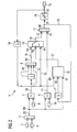
- FIG. 1 a block diagram of a control circuit is shown.
- a value for a control deviation 25 is formed from a setpoint value 2 and an actual value 4 as an output signal 80 and fed to the further block 5. If the controller has an inverse effect, the signs must be exchanged.
- the output signal 80 of the subtractor 3 is applied to one input of the other Block 5 forwarded.
- the further module 5 has a further input which is connected to an output of a memory module 6.
- a value is stored, which is forwarded as an output signal to the other module 5.
- the value stored in memory module 6 is also referred to as constant K P.
- the further module 5 is designed such that the value of the control deviation 25 is multiplied by the value stored in the memory module 6 and is forwarded as the output signal 59 to a first input 61 of a switching-addition module 60.
- the output signal 80 is also forwarded to an integral increment module 9 where it is multiplied by a value 10 and forwarded as the output signal 71 to the switching-addition module 60.
- the value 10 is formed from the quotient with a cycle time ⁇ T and an integral time TN of an integrator.
- the switching-addition module 60 has four inputs: the first input 61 for the output signal 59 of the further module 5, a second input 62 for an output signal 71 of the integral increment module 9, a third input 63 for a switching signal 21 a switching component 12 and a fourth input 64 for a voltage applied to an output 82 of a minimum-maximum limiter 14 manipulated variable signal 15.
- the switching module 12 has three inputs 65, 66, 67 on. At the input 67, the output signal 80 of the subtracting device 3 is applied, at the input 65 is a controller output signal 23 and at the input 66 is the manipulated variable signal 15 at.
- the operation of the switching module 12 is in the FIG. 4 described.
- An output signal 68 of the switching-addition module 60 is applied to an input 81 of the minimum-maximum limiter 14.
- the switching addition module 60 is configured to switch between a first state in the the output signal 59 of the further module 5 is added to calculate the manipulated variable signal 15 and a second state, in which changes in the output signal 59 of the further module 5 are blocked, can be switched over.
- the switching addition module 60 in this embodiment includes a switching device 13 and an adding device 11.
- the switching device 13 has the third input 63 and the fourth input 64.
- the addition module 11 has the second input 62 and a fifth input 72, which is connected to an output signal 18 of the switching module 13.
- the first input 61 and the fourth input 64 are provided at an adder 8, which supplies an output signal 83, which is applied to a sixth input 69 of the switching module 13.
- the output signal 59 is formed, which is referred to as a further proportion, which is used to calculate the manipulated variable signal 15.
- This additional share is in this case a proportional share.
- the manipulated variable signal 15 is forwarded via a first latch block 16 to the adder block 8 and is also referred to as Confirmed signal Y Re.
- the controller output signal 23, which is applied to the input 81 of the minimum-maximum limiter 14 is forwarded via a second latch module 17 to the switching module 12.
- Changes in the further portion from the further module 5 are further processed compared to a previous processing step.
- the output signal 59 from the further module 5 passes to a third buffer module 7 and from there to the adder module 8.
- the third buffer module 7 may be formed as a holding member 1st order. This can be represented, for example, by a corresponding execution order of the program modules.
- the output signal 59 from the further module 5 is also fed directly to the adder 8. This provides the possibility of processing only changes in the output signal 59 over a cycle time in the adder module 8.
- the output signal 80 of the subtracting module 3 is applied to the input 67 of the switching module 12.
- the switching module 12 is in FIG. 4 described in more detail.
- the output signal 18 is applied to the fifth input 72 of the adder 11 and is multiplied there by the output signal 71 of the integral increment module 9.
- the controller output signal 23 is applied.
- the controller output signal 23 is limited by means of the minimum-maximum limiter 14 and is then present as a manipulated variable signal 15.
- An output of the switching component 12 is applied to the third input 63 of the switching module 13.
- the signal coming from the first intermediate memory module 16 is applied to the fourth input 64 of the switching component 13 and to the input 66 of the switching component 12.
- the function of the switching module 13 depends on the output of the switching module 12. In an unlimited operation of the switching module has 13 in the FIG. 2 described position. If the switching component 12 delivers a switching signal 21 with a logical value 1, the function of the switching component 13 changes as follows: the output signal 18 is no longer transmitted via a line 19 at the sixth input 69 but via a line 20 at the fourth input 64 formed.
- the manipulated variable signal 15 calculated and applied in a previous cycle becomes after the first Buffer block 16 added as an operating point.
- buffer memory modules 7, 16 and 17 is to be clarified that is used with arithmetic values of a last cycle.
- the switching component 12 delivers a switching signal 21 with a logical value 1, then the change in the further component which is applied as an output signal 59 to the further component 5 is neglected.
- the new controller output signal 23 is produced in the adder module 11 by the addition of the output signal 71 of the integral increment module 9 with the signal Y return from the first intermediate memory component 16.
- the controller output signal 23 is output by a controller subprogram or externally, for example by a minimum value. or maximum selection with output signals from other controllers limited.
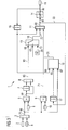
- FIG. 3 a further embodiment of the control circuit is shown.
- a signal is forwarded directly to the addition module 11 after the first buffer module 16.
- the addition module 11 now has a further input, which is connected to the first intermediate memory module 16.
- the in FIG. 3 illustrated adder 8 now has, in contrast to the embodiment of in FIG. 2 shown adder 8 only two inputs. This leads to the advantage that the manipulated variable signal 15 in accordance with FIG. 3 is applied directly to the addition block 11 via the first buffer block 16 and the manipulated variable signal 15 is applied to the addition block 11 independently of the switching block 13.
- the switching module 13 has a seventh input 73, at which a signal is applied, which corresponds to the value zero.
- the switching module 12 is shown in more detail.
- the core idea here is to switch the structure of the controller with active limitation depending on the control deviation 25.
- the switching signal 21 of the switching module 12 may assume a value corresponding to a logical value of one or zero.
- the manipulated variable signal 15 is compared with the controller output signal 23 in the block 24.
- the value of the control deviation 25 is compared in block 26 with a predefinable positive control limit value X w, positive 27. If the manipulated variable signal 15 is smaller than the controller output signal 23 and the value of the control deviation 25 is greater than or equal to the positive control limit value X w, positive 27, then the switching signal 21 corresponds to a logic value 1.
- the manipulated variable signal 15 is also sent to the module 28 in FIG a negative limit is taken into account. Also to the block 28, the controller output signal 23 is passed. The value of the control deviation 25 is compared in block 29 with a predefinable negative limit value X w, negative 30. If the manipulated variable signal 15 is greater than the controller output signal 23 and the value of the control deviation 25 is less than or equal to the negative control limit value X w, negative 30, a switching signal 21 is formed via an AND component 31 and an OR component 32, which is a logical Value equals one.
- the switching module 12 supplies a value which corresponds to a logic value zero and the control algorithm is switched over.
- control circuit may be designed such that an inverse effective sense is possible.
- the output signal drops as the setpoint increases. This is achieved by swapping the inputs to the subtractor 3 and the adder 46.
- the first buffer module 16 is connected to an external signal generator. Via the external signal generator, other controllers or other signals are taken into account via minimum and maximum selections.
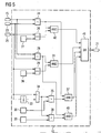
- FIG. 5 a further embodiment of the switching module 12 is shown. Compared to the in FIG. 4 illustrated embodiment of the switching module 12 are in the FIG. 5 contain further blocks which create the possibility of taking into account the noise of the control deviation 25.
- the value of the control deviation 25 is applied to a block 35 via a further buffer block 33 and a block 34.
- a change in the value of the control deviation 25 is compared with a predefinable limit value ⁇ X w, positive 36. If the condition occurs that the change in the value of the system deviation 25 is greater than the limit value ⁇ X w, positive 36, a logic signal is forwarded to the module 37.
- the block 37 is an AND block.
- the change in the value of the control deviation 25 is also forwarded to the block 38.
- the change in the value of the control deviation 25 is compared with a predefinable negative limit value ⁇ X w, negative 39. If the change in the value of the control deviation 25 is smaller than the limit value ⁇ X w, negative 39, then a value which corresponds to a logic value 1 is forwarded to the module 40.
- the module 40 is an AND component. For this block 40, the signal is passed, which comes from the block 28.
- the block 41 is an OR block, which is connected to the block 32 from the FIG. 3 is comparable.
- the OR block 41 now has 4 inputs, which come from the blocks 42, 31, 37 and 40.
- the illustrated latch 33 may also be a higher order latch or any discrete filter, delay element, or deadtime element.
- the further portion has a proportional component.
- a further advantageous embodiment of the control circuit is shown, wherein the further portion now has the proportional component and a differential component.
- a Differenzialanteil Bustein 42 a value for the differential component of the setpoint 2, the actual value 4, the manipulated variable signal 15 and the controller output signal 23 is formed and forwarded to an adder module 43 as an output signal 19. The calculation of the differential component takes place according to the procedures described in the prior art.
- the output signal 19 of the differential component 42 and the further component 5 is added to an output signal 44 and forwarded to the adder module 8 via the third intermediate memory component 7 and from there via the switchover component 13 the adder module 11 continued.
- the further portion now has a differential component and a proportional component.
- the FIG. 7 shows an embodiment of the differential component block 42.
- the setpoint 2 and the actual value 4 are forwarded to an adder 46. After the adder module 46, a signal is sent to a switchover component 47.
- the actual value 4 is likewise forwarded directly to the switchover component 47.
- the actual value 4 can be multiplied by a factor of -1 multiplied before the resulting inverted signal enters the switching module 47. About the switching module 47, it is possible to take changes in the setpoint 2 to calculate the differential component.
- the block 58 With the block 58, a value is forwarded to an input 75 of a multiplication block 50 with an output signal 74 of the switching block 47.
- the block 58 is not a delay block, but a so-called DT1 element. It filters and differentiates to some extent at the same time.
- the multiplication component 50 has a second input 76.
- the manipulated variable signal 15 and the controller output signal 23 are compared in comparison module 52.
- the comparison module 52 provides an output signal 77, which is forwarded to a switching module 53. If the values of the regulator output signal 23 and the manipulated variable signal 15 are equal, the comparison component 52 supplies a logical value 1 as output signal 77 and otherwise a logic value zero.
- the switching module 53 has a first input 78 connected to a memory module 57 having the value zero and a second input 79 connected to a second memory module 56 containing a value for a holding time 84.
- An output signal 54 is applied to an input 85 of a slope limiting module 55.
- the value of the memory component 56 is forwarded to the slope limiting component 55. Otherwise, the value zero of the memory module 57 is forwarded to the slope limiting module 55.
- An output signal 51 of the slope limiting module 55 is applied to the second input 76 of the multiplication module 50.
- the signals applied to the inputs 75 and 76 are multiplied to the output signal 19. In this way, the differentiating proportion of the setting range limits is taken out. Signal noise no longer leads to leaving the boundary. A bumpless reinstatement of the differentiating portion is guaranteed.
Landscapes
- Physics & Mathematics (AREA)
- General Physics & Mathematics (AREA)
- Engineering & Computer Science (AREA)
- Automation & Control Theory (AREA)
- Feedback Control In General (AREA)
Claims (25)
- Procédé de régulation d'une grandeur de réglage, qui peut être modifié par un signal ( 15 ) de grandeur de réglage que l'on calcule, en fonction d'une valeur ( 2 ) de consigne et d'une valeur ( 4 ) réelle de la grandeur de réglage, par un algorithme de réglage, lequel a une composante intégrale et une autre composante,
dans lequel on calcule le signal ( 15 ) de grandeur de réglage, la composante intégrale et l'autre composante par l'algorithme de réglage,
caractérisé en ce que
l'on calcule la valeur du signal ( 15 ) de grandeur de réglage d'abord par l'algorithme de réglage et on la limite suivant un limiteur ( 14 ) de minimum-maximum et on la renvoie à l'algorithme de réglage,
une modification de l'autre composante étant négligée si les conditions suivantes sont satisfaites :- la valeur calculée par l'algorithme de réglage du signal ( 15 ) de grandeur de réglage est plus grande que la valeur qui a été limitée suivant le limiteur ( 14 ) de minimum-maximum et- un écart ( 25 ) de réglage, qui a été déterminé à partir de la différence entre la valeur ( 2 ) de consigne et la valeur ( 4 ) réelle de la grandeur de réglage, est supérieur ou égal à une valeur XW,positiv limite donnée à l'avanceou- la valeur calculée par l'algorithme de réglage du signal ( 15 ) de grandeur de réglage est plus petite que la valeur, qui a été limitée suivant le limiteur ( 14 ) de minimum-maximum, et- l'écart ( 25 ) de réglage est inférieur ou égal à une valeur XW,négativ limite pouvant être donnée à l'avance. - Procédé suivant la revendication 1,
caractérisé en ce que
l'autre composante est une composante proportionnelle. - Procédé suivant la revendication 1 ou 2,
caractérisé en ce que
l'algorithme de réglage a une composante différentielle. - Procédé suivant l'une des revendications 1 à 3,
caractérisé en ce que
l'on ajoute la composante différentielle à l'autre composante. - Procédé suivant l'une des revendications 1 à 4,
caractérisé en ce que
l'on néglige l'autre composante si la condition suivante est en outre satisfaite :- le signal a été limité vers le haut et- une variation de l'écart ( 25 ) de réglage est plus grande qu'une valeur Δ XW,positiv limite donnée à l'avanceou- le signal a été limité vers le bas et- une variation de l'écart ( 25 ) de réglage est plus petite qu'une valeur Δ XW,negativ limite pouvant être donnée à l'avance. - Procédé suivant l'une des revendications 3 à 5,
caractérisé en ce que
l'on peut tenir compte de variations de la valeur ( 2 ) de consigne pour le calcul de la composante différentielle. - Procédé suivant l'une des revendications 3 à 6,
caractérisé en ce que
l'on filtre la composante différentielle par une constante de temps réglable. - Utilisation du procédé suivant l'une des revendications 1 à 7 pour le fonctionnement d'un compresseur.
- Dispositif de régulation d'une grandeur de réglage, qui peut être modifiée par un signal ( 15 ) de grandeur de réglage, comprenant un module ( 3 ) de soustraction pour le calcul d'un écart ( 25 ) de réglage par soustraction d'une valeur ( 2 ) de consigne de la grandeur de réglage d'une valeur ( 4 ) réelle de la grandeur de réglage,
un module ( 9 ) d'intégral-incrément pour le calcul d'une composante d'incrément intégral du signal ( 15 ) de grandeur de réglage comme signal de sortie sur la base de l'écart ( 25 ) de régulation,
un autre module ( 5 ) pour le calcul d'une autre composante du signal ( 15 ) de grandeur de réglage comme signal de sortie sur la base de l'écart ( 25 ) de réglage,
un module ( 60 ) de commutation-addition,
qui a une première entrée ( 61 ) pour le signal de sortie de l'autre module ( 5 ),
qui a une deuxième entrée ( 62 ) pour le signal ( 71 ) de sortie du module ( 9 ) d'intégral-incrément,
caractérisé par
une troisième entrée ( 63 ) qu'a le module ( 60 ) de commutation-addition pour un signal ( 21 ) de commutation et une quatrième entrée ( 64 ) qu'a le module ( 60 ) de commutation-addition pour un signal provenant du limiteur ( 14 ) de minimum-maximum, lequel est constitué pour la limitation de la valeur du signal ( 15 ) de grandeur de réglage à une valeur réglée à l'avance et
est constitué pour le calcul d'une valeur de la grandeur ( 15 ) de réglage comme grandeur de sortie sur la base de l'autre module ( 5 ) du signal de sortie du module ( 9 ) d'intégral-incrément et du signal ( 22 ) du limiteur ( 14 ) de minimum-maximum,
le module ( 60 ) de commutation-addition pouvant être commuté entre un premier état dans lequel le signal de sortie de l'autre module ( 5 ) est additionné pour le calcul du signal ( 15 ) de la grandeur de réglage et un deuxième état dans lequel le signal de sortie de l'autre module ( 5 ) est bloqué et
un module ( 12 ) de commutation pour produire le signal ( 21 ) de commutation pour le module ( 60 ) de commutation-addition, le module ( 12 ) de commutation étant constitué de manière à envoyer un signal ( 21 ) de commutation au module ( 60 ) de commutation-addition pour le passage dans le deuxième état, si la valeur du signal ( 15 ) de grandeur de réglage est plus grande que la valeur réglée à l'avance suivant le limiteur de minimum-maximum et si l'écart ( 25 ) de régulation est supérieur ou égal à une valeur XW,positiv pouvant être donnée à l'avance
ou
si la valeur du signal ( 15 ) de grandeur de réglage est plus petite que la valeur réglée à l'avance suivant le limiteur ( 14 ) de minimum-maximum et l'écart ( 25 ) de régulation est inférieur ou égal à une valeur XW,negativ limite donnée à l'avance. - Dispositif suivant la revendication 9,
caractérisé en ce que
le module ( 12 ) de commutation est constitué de manière à envoyer un signal ( 21 ) de commutation du module ( 12 ) de commutation au module ( 60 ) de commutation-addition, si la valeur du signal ( 15 ) de grandeur de réglage est plus grande que la valeur réglée suivant le limiteur ( 14 ) de minimum-maximum
et
si une variation de l'écart ( 25 ) de réglage est plus grande qu'une valeur Δ XW,positiv limite pouvant être donnée à l'avance ou
si la valeur du signal ( 15 ) de grandeur de réglage est plus petite que la valeur réglée suivant le limiteur ( 14 ) de minimum-maximum
et
si une variation de l'écart ( 25 ) de réglage est plus petite qu'une valeur Δ XW,negativ limite pouvant être donnée à l'avance. - Dispositif suivant la revendication 9 ou 10,
caractérisé en ce que
le module ( 60 ) de commutation-addition comprend un module ( 13 ) de commutation ayant une première ( 61 ), troisième ( 63 ) et quatrième ( 64 ) entrées et un module ( 11 ) d'addition ayant la deuxième entrée ( 62 ) et une cinquième entrée ( 72 ) pour un signal ( 18 ) de sortie du module ( 13 ) de commutation. - Dispositif suivant la revendication 11,
caractérisé en ce que
dans le module ( 13 ) de commutation, la première ( 61 ) et la quatrième ( 64 ) sont rassemblées en une sixième entrée ( 69 ) pour un signal, qui est formé de la somme du signal de sortie de l'autre module ( 5 ) et du signal du limiteur ( 14 ) de minimum-maximum,
le module ( 13 ) de commutation a la quatrième entrée ( 64 ) pour le signal du limiteur ( 14 ) de minimum-maximum et la troisième entrée ( 63 ) pour le signal ( 21 ) de commutation de commutation,
ainsi que
peut passer entre un premier état, dans lequel seul le signal à la sixième entrée ( 69 ) passe comme signal ( 18 ) de sortie, et un deuxième état, dans lequel seul le signal à la quatrième entrée ( 64 ) passe comme signal ( 18 ) de sortie. - Dispositif suivant la revendication 12,
caractérisé en ce que
le module ( 11 ) d'addition est constitué pour l'addition du signal ( 18 ) de sortie du module ( 13 ) de commutation et du signal ( 71 ) de sortie du module ( 9 ) d'intégral-incrément en un signal de sortie. - Dispositif suivant la revendication 9 ou 10,
caractérisé en ce que
le module ( 60 ) de commutation-addition a un module ( 13 ) de commutation ayant la première ( 61 ) et la troisième ( 63 ) entrées et un module ( 11 ) d'addition ayant la deuxième ( 62 ) et la quatrième ( 64 ) entrées et la cinquième entrée ( 72 ) pour le signal ( 18 ) de sortie du module ( 13 ) de commutation. - Dispositif suivant la revendication 14,
caractérisé en ce que
le module ( 13 ) de commutation
a une septième ( 73 ) entrée pour un signal ayant la valeur 0 ainsi que
peut passer entre un premier état, dans lequel le signal ( 59 ) de sortie de l'autre module passe comme signal ( 18 ) de sortie, et
un deuxième état, dans lequel c'est le signal ayant la valeur 0 qui passe. - Dispositif suivant la revendication 15,
caractérisé en ce que
le module ( 11 ) d'addition est constitué pour l'addition du signal ( 18 ) de sortie du module ( 13 ) de commutation, du signal ( 71 ) de sortie du module ( 9 ) d'intégral-incrément et du signal du limiteur ( 14 ) de minimum-maximum en un signal ( 68 ) de sortie. - Dispositif suivant l'une des revendications 9 à 16,
caractérisé en ce que
l'autre module ( 5 ) comprend un module de composante proportionnelle et un module ( 42 ) de composante différentielle. - Dispositif suivant la revendication 17,
caractérisé en ce que
le module ( 42 ) de composante différentielle est prévu pour le calcul d'une composante différentielle du signal ( 15 ) de grandeur de réglage comme signal de sortie sur la base de l'écart ( 25 ) de réglage,
du signal ( 22 ) du limiteur ( 14 ) de minimum-maximum et
d'un signal ( 23 ) de sortie du module ( 11 ) d'addition. - Dispositif suivant la revendication 17 ou 18,
caractérisé en ce que
le module ( 5 ) de composante proportionnelle est prévu pour le calcul d'une composante proportionnelle du signal ( 15 ) de grandeur de réglage comme signal de sortie sur la base de l'écart ( 25 ) de réglage. - Dispositif suivant l'une des revendications 16 à 19,
caractérisé en ce que
un module ( 11 ) d'addition est prévu pour l'addition du signal de sortie du module ( 42 ) de composante différentielle et du signal de sortie du module ( 5 ) de composante proportionnelle comme signal de sortie de l'autre composante. - Dispositif suivant l'une des revendications 16 ou 20,
caractérisé en ce que
le module ( 42 ) de composante différentielle a un module ( 13 ) de commutation qui
a une première entrée pour la valeur de la grandeur de réglage et
une deuxième entrée pour la valeur de l'écart ( 25 ) de réglage
ainsi que
passe entre un premier état, dans lequel passe la variation de la valeur ( 2 ) de consigne, et un deuxième état, dans lequel seul l'écart ( 25 ) de réglage est acheminé. - Dispositif suivant l'une des revendications 9 à 21,
caractérisé en ce que
le module ( 42 ) de composante différentielle a un module ( 48 ) de temporisation pour le calcul de la composante différentielle. - Dispositif suivant l'une des revendications 9 à 22,
caractérisé en ce qu'
un premier module ( 16 ) de mémoire intermédiaire est prévu pour mémoriser intermédiairement un signal comme signal de sortie,
module qui est relié au signal présent suivant le limiteur ( 14 ) de minimum-maximum et
le signal de sortie du premier module ( 16 ) de mémoire intermédiaire est relié au module ( 60 ) de commutation-addition ou au module ( 11 ) d'addition. - Dispositif suivant l'une des revendications 9 à 23,
caractérisé en ce que
un deuxième module ( 17 ) de mémoire intermédiaire est prévu pour la mémorisation intermédiaire d'un signal comme signal de sortie,
module qui est relié au signal de sortie du module ( 11 ) d'addition et
le signal de sortie du module ( 17 ) de mémoire intermédiaire est relié au module ( 12 ) de commutation. - Dispositif suivant l'une des revendications 9 à 24,
caractérisé en ce que
un troisième module ( 7 ) de mémoire intermédiaire est prévu pour la mémorisation intermédiaire d'un signal comme signal de sortie,
module qui est relié au signal de sortie de l'autre module ( 5 ) et
le signal de sortie de l'autre module de mémoire intermédiaire est relié à la première entrée ( 61 ) du module ( 60 ) de commutation-addition.
Priority Applications (1)
| Application Number | Priority Date | Filing Date | Title |
|---|---|---|---|
| EP03020210.5A EP1513033B1 (fr) | 2003-09-05 | 2003-09-05 | Procédé et dispositif de commande d'une grandeur de réglage |
Applications Claiming Priority (1)
| Application Number | Priority Date | Filing Date | Title |
|---|---|---|---|
| EP03020210.5A EP1513033B1 (fr) | 2003-09-05 | 2003-09-05 | Procédé et dispositif de commande d'une grandeur de réglage |
Publications (2)
| Publication Number | Publication Date |
|---|---|
| EP1513033A1 EP1513033A1 (fr) | 2005-03-09 |
| EP1513033B1 true EP1513033B1 (fr) | 2016-08-31 |
Family
ID=34130156
Family Applications (1)
| Application Number | Title | Priority Date | Filing Date |
|---|---|---|---|
| EP03020210.5A Expired - Lifetime EP1513033B1 (fr) | 2003-09-05 | 2003-09-05 | Procédé et dispositif de commande d'une grandeur de réglage |
Country Status (1)
| Country | Link |
|---|---|
| EP (1) | EP1513033B1 (fr) |
Family Cites Families (4)
| Publication number | Priority date | Publication date | Assignee | Title |
|---|---|---|---|---|
| US5189620A (en) * | 1989-10-06 | 1993-02-23 | United Technologies Corporation | Control system for gas turbine helicopter engines and the like |
| US5270916A (en) * | 1990-02-27 | 1993-12-14 | Ge Fanuc Automation North America, Inc. | Apparatus and method for preventing runaway of the integral term of a proportional plus integral controller |
| US5231341A (en) * | 1991-09-18 | 1993-07-27 | Samsung Electronics Co., Ltd. | Limiter circuit of servo motor control apparatus |
| US5298845A (en) * | 1991-10-31 | 1994-03-29 | Johnson Service Company | Anti-windup proportional plus integral controller |
-
2003
- 2003-09-05 EP EP03020210.5A patent/EP1513033B1/fr not_active Expired - Lifetime
Also Published As
| Publication number | Publication date |
|---|---|
| EP1513033A1 (fr) | 2005-03-09 |
Similar Documents
| Publication | Publication Date | Title |
|---|---|---|
| DE68926600T2 (de) | Digitales Regelsystem | |
| EP0132487B1 (fr) | Procédé de régulation d'au moins deux turbo-compresseurs branchés en parallèle | |
| DE69206805T2 (de) | Selbstanpassende begrenzungsvorrichtung für die eingangsignale eines steuerungssystems | |
| DE4104642C2 (de) | PID- bzw. PI-Regler | |
| DE69007874T2 (de) | Regelungsanordnung für ein Verfahrensinstrumentierungssystem. | |
| DE2347741A1 (de) | Prozessregelorgan mit selbsttaetiger anpassung an unbekannte oder veraenderliche parameter | |
| EP2579112A1 (fr) | Dispositif de régulation | |
| DE2627591A1 (de) | Regeleinrichtung fuer turbinen mit drehzahl- und leistungsregelung | |
| EP1119799A1 (fr) | Dispositif de regulation pour la regulation d'un systeme asservi a plusieurs grandeurs reglees couplees | |
| EP1540431B1 (fr) | Procede de regulation du courant traversant un element d'ajustement electromagnetique | |
| DE4418997C2 (de) | Feldorientierte Regelung für einen über einen Spannungs-Pulswechselrichter gespeisten Drehstrommotor | |
| EP1490735B1 (fr) | Procede et regulateur permettant la regulation adaptative d'au moins une composante d'une installation technique | |
| EP0752630B1 (fr) | Contrôleur et méthode pour l'auto-ajustement du contrôleur | |
| EP1513033B1 (fr) | Procédé et dispositif de commande d'une grandeur de réglage | |
| DE102014003084A1 (de) | Digitalhydraulisches Antriebssystem | |
| EP3652597A1 (fr) | Évaluation automatique d'un comportement de machine | |
| WO2018060230A1 (fr) | Dispositif de régulation avec ajustabilité du comportement de régulation | |
| DE3541148C3 (de) | Verfahren zur Regelung einer Dampfturbine | |
| DE69114623T2 (de) | Regelungssystem des Typs mit zwei Freiheitsgraden. | |
| DE69330976T2 (de) | Regelungsmethode zur Erreichung eines Sollwertes | |
| DE4038212C1 (en) | PID regulator based on microprocessor - has P-, I- and D-elements in parallel channels with switch unit in I-channel | |
| DE10055166C5 (de) | Verfahren zur Regelung der Leistung und Drehzahl einer Turbine | |
| EP2482147B1 (fr) | Procédé d'adaptation de la fréquence de cadence d'un microprocesseur d'un composant d'automatisation industriel et composants d'automatisation dotés d'un microprocesseur ayant une fréquence de cadence modifiable | |
| AT391564B (de) | Regler mit begrenzungseinrichtung | |
| DE102013003571B4 (de) | Gleitmodusregelvorrichtung |
Legal Events
| Date | Code | Title | Description |
|---|---|---|---|
| PUAI | Public reference made under article 153(3) epc to a published international application that has entered the european phase |
Free format text: ORIGINAL CODE: 0009012 |
|
| AK | Designated contracting states |
Kind code of ref document: A1 Designated state(s): AT BE BG CH CY CZ DE DK EE ES FI FR GB GR HU IE IT LI LU MC NL PT RO SE SI SK TR |
|
| AX | Request for extension of the european patent |
Extension state: AL LT LV MK |
|
| 17P | Request for examination filed |
Effective date: 20050404 |
|
| AKX | Designation fees paid |
Designated state(s): AT BE BG CH CY CZ DE DK EE ES FI FR GB GR HU IE IT LI LU MC NL PT RO SE SI SK TR |
|
| 17Q | First examination report despatched |
Effective date: 20110131 |
|
| RAP1 | Party data changed (applicant data changed or rights of an application transferred) |
Owner name: SIEMENS AKTIENGESELLSCHAFT |
|
| RAP1 | Party data changed (applicant data changed or rights of an application transferred) |
Owner name: SIEMENS AKTIENGESELLSCHAFT |
|
| GRAP | Despatch of communication of intention to grant a patent |
Free format text: ORIGINAL CODE: EPIDOSNIGR1 |
|
| INTG | Intention to grant announced |
Effective date: 20160323 |
|
| GRAS | Grant fee paid |
Free format text: ORIGINAL CODE: EPIDOSNIGR3 |
|
| GRAA | (expected) grant |
Free format text: ORIGINAL CODE: 0009210 |
|
| AK | Designated contracting states |
Kind code of ref document: B1 Designated state(s): AT BE BG CH CY CZ DE DK EE ES FI FR GB GR HU IE IT LI LU MC NL PT RO SE SI SK TR |
|
| REG | Reference to a national code |
Ref country code: CH Ref legal event code: EP Ref country code: CH Ref legal event code: NV Representative=s name: SIEMENS SCHWEIZ AG, CH Ref country code: GB Ref legal event code: FG4D Free format text: NOT ENGLISH |
|
| REG | Reference to a national code |
Ref country code: IE Ref legal event code: FG4D Free format text: LANGUAGE OF EP DOCUMENT: GERMAN |
|
| REG | Reference to a national code |
Ref country code: DE Ref legal event code: R096 Ref document number: 50315530 Country of ref document: DE |
|
| REG | Reference to a national code |
Ref country code: AT Ref legal event code: REF Ref document number: 825493 Country of ref document: AT Kind code of ref document: T Effective date: 20161015 |
|
| REG | Reference to a national code |
Ref country code: NL Ref legal event code: FP |
|
| PG25 | Lapsed in a contracting state [announced via postgrant information from national office to epo] |
Ref country code: FI Free format text: LAPSE BECAUSE OF FAILURE TO SUBMIT A TRANSLATION OF THE DESCRIPTION OR TO PAY THE FEE WITHIN THE PRESCRIBED TIME-LIMIT Effective date: 20160831 |
|
| PG25 | Lapsed in a contracting state [announced via postgrant information from national office to epo] |
Ref country code: GR Free format text: LAPSE BECAUSE OF FAILURE TO SUBMIT A TRANSLATION OF THE DESCRIPTION OR TO PAY THE FEE WITHIN THE PRESCRIBED TIME-LIMIT Effective date: 20161201 Ref country code: BE Free format text: LAPSE BECAUSE OF NON-PAYMENT OF DUE FEES Effective date: 20160930 Ref country code: ES Free format text: LAPSE BECAUSE OF FAILURE TO SUBMIT A TRANSLATION OF THE DESCRIPTION OR TO PAY THE FEE WITHIN THE PRESCRIBED TIME-LIMIT Effective date: 20160831 Ref country code: SE Free format text: LAPSE BECAUSE OF FAILURE TO SUBMIT A TRANSLATION OF THE DESCRIPTION OR TO PAY THE FEE WITHIN THE PRESCRIBED TIME-LIMIT Effective date: 20160831 |
|
| PG25 | Lapsed in a contracting state [announced via postgrant information from national office to epo] |
Ref country code: EE Free format text: LAPSE BECAUSE OF FAILURE TO SUBMIT A TRANSLATION OF THE DESCRIPTION OR TO PAY THE FEE WITHIN THE PRESCRIBED TIME-LIMIT Effective date: 20160831 Ref country code: RO Free format text: LAPSE BECAUSE OF FAILURE TO SUBMIT A TRANSLATION OF THE DESCRIPTION OR TO PAY THE FEE WITHIN THE PRESCRIBED TIME-LIMIT Effective date: 20160831 |
|
| PG25 | Lapsed in a contracting state [announced via postgrant information from national office to epo] |
Ref country code: DK Free format text: LAPSE BECAUSE OF FAILURE TO SUBMIT A TRANSLATION OF THE DESCRIPTION OR TO PAY THE FEE WITHIN THE PRESCRIBED TIME-LIMIT Effective date: 20160831 Ref country code: CZ Free format text: LAPSE BECAUSE OF FAILURE TO SUBMIT A TRANSLATION OF THE DESCRIPTION OR TO PAY THE FEE WITHIN THE PRESCRIBED TIME-LIMIT Effective date: 20160831 Ref country code: SK Free format text: LAPSE BECAUSE OF FAILURE TO SUBMIT A TRANSLATION OF THE DESCRIPTION OR TO PAY THE FEE WITHIN THE PRESCRIBED TIME-LIMIT Effective date: 20160831 Ref country code: PT Free format text: LAPSE BECAUSE OF FAILURE TO SUBMIT A TRANSLATION OF THE DESCRIPTION OR TO PAY THE FEE WITHIN THE PRESCRIBED TIME-LIMIT Effective date: 20170102 Ref country code: BG Free format text: LAPSE BECAUSE OF FAILURE TO SUBMIT A TRANSLATION OF THE DESCRIPTION OR TO PAY THE FEE WITHIN THE PRESCRIBED TIME-LIMIT Effective date: 20161130 |
|
| REG | Reference to a national code |
Ref country code: DE Ref legal event code: R097 Ref document number: 50315530 Country of ref document: DE |
|
| REG | Reference to a national code |
Ref country code: IE Ref legal event code: MM4A |
|
| PLBE | No opposition filed within time limit |
Free format text: ORIGINAL CODE: 0009261 |
|
| STAA | Information on the status of an ep patent application or granted ep patent |
Free format text: STATUS: NO OPPOSITION FILED WITHIN TIME LIMIT |
|
| GBPC | Gb: european patent ceased through non-payment of renewal fee |
Effective date: 20161130 |
|
| PG25 | Lapsed in a contracting state [announced via postgrant information from national office to epo] |
Ref country code: IE Free format text: LAPSE BECAUSE OF NON-PAYMENT OF DUE FEES Effective date: 20160905 |
|
| 26N | No opposition filed |
Effective date: 20170601 |
|
| REG | Reference to a national code |
Ref country code: FR Ref legal event code: ST Effective date: 20170713 |
|
| PG25 | Lapsed in a contracting state [announced via postgrant information from national office to epo] |
Ref country code: LU Free format text: LAPSE BECAUSE OF NON-PAYMENT OF DUE FEES Effective date: 20160905 Ref country code: SI Free format text: LAPSE BECAUSE OF FAILURE TO SUBMIT A TRANSLATION OF THE DESCRIPTION OR TO PAY THE FEE WITHIN THE PRESCRIBED TIME-LIMIT Effective date: 20160831 |
|
| REG | Reference to a national code |
Ref country code: CH Ref legal event code: PCOW Free format text: NEW ADDRESS: WERNER-VON-SIEMENS-STRASSE 1, 80333 MUENCHEN (DE) |
|
| PG25 | Lapsed in a contracting state [announced via postgrant information from national office to epo] |
Ref country code: FR Free format text: LAPSE BECAUSE OF NON-PAYMENT OF DUE FEES Effective date: 20161102 |
|
| REG | Reference to a national code |
Ref country code: AT Ref legal event code: MM01 Ref document number: 825493 Country of ref document: AT Kind code of ref document: T Effective date: 20160905 |
|
| REG | Reference to a national code |
Ref country code: BE Ref legal event code: MM Effective date: 20160930 |
|
| PG25 | Lapsed in a contracting state [announced via postgrant information from national office to epo] |
Ref country code: GB Free format text: LAPSE BECAUSE OF NON-PAYMENT OF DUE FEES Effective date: 20161130 |
|
| PG25 | Lapsed in a contracting state [announced via postgrant information from national office to epo] |
Ref country code: AT Free format text: LAPSE BECAUSE OF NON-PAYMENT OF DUE FEES Effective date: 20160905 |
|
| PG25 | Lapsed in a contracting state [announced via postgrant information from national office to epo] |
Ref country code: CY Free format text: LAPSE BECAUSE OF FAILURE TO SUBMIT A TRANSLATION OF THE DESCRIPTION OR TO PAY THE FEE WITHIN THE PRESCRIBED TIME-LIMIT Effective date: 20160831 Ref country code: HU Free format text: LAPSE BECAUSE OF FAILURE TO SUBMIT A TRANSLATION OF THE DESCRIPTION OR TO PAY THE FEE WITHIN THE PRESCRIBED TIME-LIMIT; INVALID AB INITIO Effective date: 20030905 |
|
| PG25 | Lapsed in a contracting state [announced via postgrant information from national office to epo] |
Ref country code: MC Free format text: LAPSE BECAUSE OF FAILURE TO SUBMIT A TRANSLATION OF THE DESCRIPTION OR TO PAY THE FEE WITHIN THE PRESCRIBED TIME-LIMIT Effective date: 20160831 Ref country code: TR Free format text: LAPSE BECAUSE OF FAILURE TO SUBMIT A TRANSLATION OF THE DESCRIPTION OR TO PAY THE FEE WITHIN THE PRESCRIBED TIME-LIMIT Effective date: 20160831 |
|
| REG | Reference to a national code |
Ref country code: DE Ref legal event code: R081 Ref document number: 50315530 Country of ref document: DE Owner name: SIEMENS ENERGY GLOBAL GMBH & CO. KG, DE Free format text: FORMER OWNER: SIEMENS AKTIENGESELLSCHAFT, 80333 MUENCHEN, DE |
|
| PGFP | Annual fee paid to national office [announced via postgrant information from national office to epo] |
Ref country code: NL Payment date: 20220908 Year of fee payment: 20 Ref country code: DE Payment date: 20220617 Year of fee payment: 20 |
|
| REG | Reference to a national code |
Ref country code: NL Ref legal event code: PD Owner name: SIEMENS ENERGY GLOBAL GMBH & CO. KG; DE Free format text: DETAILS ASSIGNMENT: CHANGE OF OWNER(S), ASSIGNMENT; FORMER OWNER NAME: SIEMENS AKTIENGESELLSCHAFT Effective date: 20221220 |
|
| PGFP | Annual fee paid to national office [announced via postgrant information from national office to epo] |
Ref country code: IT Payment date: 20220926 Year of fee payment: 20 |
|
| PGFP | Annual fee paid to national office [announced via postgrant information from national office to epo] |
Ref country code: CH Payment date: 20221207 Year of fee payment: 20 |
|
| REG | Reference to a national code |
Ref country code: DE Ref legal event code: R071 Ref document number: 50315530 Country of ref document: DE |
|
| REG | Reference to a national code |
Ref country code: NL Ref legal event code: MK Effective date: 20230904 |
|
| REG | Reference to a national code |
Ref country code: CH Ref legal event code: PL |