EP1513033A1 - Verfahren und Vorrichtung zur Regelung einer Regelgrösse - Google Patents
Verfahren und Vorrichtung zur Regelung einer Regelgrösse Download PDFInfo
- Publication number
- EP1513033A1 EP1513033A1 EP03020210A EP03020210A EP1513033A1 EP 1513033 A1 EP1513033 A1 EP 1513033A1 EP 03020210 A EP03020210 A EP 03020210A EP 03020210 A EP03020210 A EP 03020210A EP 1513033 A1 EP1513033 A1 EP 1513033A1
- Authority
- EP
- European Patent Office
- Prior art keywords
- signal
- value
- output signal
- component
- switching
- Prior art date
- Legal status (The legal status is an assumption and is not a legal conclusion. Google has not performed a legal analysis and makes no representation as to the accuracy of the status listed.)
- Granted
Links
- 238000000034 method Methods 0.000 title claims description 28
- 230000008859 change Effects 0.000 claims abstract description 24
- 238000004422 calculation algorithm Methods 0.000 claims abstract description 23
- 230000006870 function Effects 0.000 claims description 4
- 230000003139 buffering effect Effects 0.000 claims 1
- 238000007792 addition Methods 0.000 description 23
- 230000006399 behavior Effects 0.000 description 9
- 238000010586 diagram Methods 0.000 description 8
- 230000008569 process Effects 0.000 description 8
- 239000013641 positive control Substances 0.000 description 5
- 230000008901 benefit Effects 0.000 description 4
- 238000004364 calculation method Methods 0.000 description 4
- 230000033228 biological regulation Effects 0.000 description 3
- 238000006243 chemical reaction Methods 0.000 description 3
- 230000010354 integration Effects 0.000 description 3
- 230000000694 effects Effects 0.000 description 2
- 230000009471 action Effects 0.000 description 1
- 230000001419 dependent effect Effects 0.000 description 1
- 238000009795 derivation Methods 0.000 description 1
- 230000004069 differentiation Effects 0.000 description 1
- 239000013642 negative control Substances 0.000 description 1
- 230000006641 stabilisation Effects 0.000 description 1
- 238000011105 stabilization Methods 0.000 description 1
- 239000000126 substance Substances 0.000 description 1
- 230000002123 temporal effect Effects 0.000 description 1
Images


Classifications
-
- G—PHYSICS
- G05—CONTROLLING; REGULATING
- G05B—CONTROL OR REGULATING SYSTEMS IN GENERAL; FUNCTIONAL ELEMENTS OF SUCH SYSTEMS; MONITORING OR TESTING ARRANGEMENTS FOR SUCH SYSTEMS OR ELEMENTS
- G05B5/00—Anti-hunting arrangements
- G05B5/01—Anti-hunting arrangements electric
-
- G—PHYSICS
- G05—CONTROLLING; REGULATING
- G05B—CONTROL OR REGULATING SYSTEMS IN GENERAL; FUNCTIONAL ELEMENTS OF SUCH SYSTEMS; MONITORING OR TESTING ARRANGEMENTS FOR SUCH SYSTEMS OR ELEMENTS
- G05B11/00—Automatic controllers
- G05B11/01—Automatic controllers electric
- G05B11/36—Automatic controllers electric with provision for obtaining particular characteristics, e.g. proportional, integral, differential
- G05B11/42—Automatic controllers electric with provision for obtaining particular characteristics, e.g. proportional, integral, differential for obtaining a characteristic which is both proportional and time-dependent, e.g. P. I., P. I. D.
Definitions
- the invention relates to a method and a device for Control of a controlled variable via a manipulated variable is changeable, depending on a setpoint and an actual value for the controlled variable with a control algorithm is calculated, one integral part and another Share, wherein the manipulated variable, the integral component and the further portion can be calculated with the control algorithm.
- a regulation is characterized by the steps: measuring, comparing and Regulate.
- a control loop serves to set the given value to set a physical variable as a controlled variable.
- controller One Means comparing the actual value and the Setpoint of the physical quantity for obtaining a Control deviation and a value for the manipulated variable determined, is called controller.
- PID or PI controllers With PID or PI controllers become the temporal behavior of a deviation between the current and desired value of physical size in a suitable manner by specifying minimizes three or two rule parameters.
- a comprehensive Description of a PID controller is z. In the textbook "Control engineering-a practice-oriented textbook", publisher Harri German, Frankfurt am Main, ISBN 3-8171-1653-5 described.
- a suction side Volume flow can be greater than that by a Rule line predetermined setpoint.
- the output of the PID or PI controller leads to a complete closure of a Control valve. However, since the PID or PI controller is still a recorded positive control deviation, the increases Integral part of the PID or PI controller. If now the Controlled variable the setpoint given by the control line below, the control valve must open immediately. There the value of the integral part of the PID or PI controller due to long operation in the range of positive control deviations has increased, this does not happen. The regulation shows only then an effect, if the negative value of the Proportional share the difference between this value and reached a threshold of the control element. It exists here the danger that the surge limit in case of Pipe limit control could be exceeded.
- the structure of the controller module of the compact controller ABB "Protronic PS2" shows the aforementioned behavior.
- the proportional component P is formed from a control deviation with the multiplication of a constant K P or division with a constant X P.
- the proportional component P is added to the output value of the integral component value I and thus forms the value Y v .
- the effective manipulated variable is formed by the value Y v is limited by a minimum or maximum limit.
- an internal feedback signal I R is formed.
- the feedback I R is formed from the difference between the effective control signal Y and the proportional component P.
- an integral increment e * ⁇ T / T N is added to this value, where e represents the control deviation, ⁇ T a cycle time and T N an integral time of an integrator. If the value of the effective actuating signal Y is equal to the value determined by the control algorithm for the actuating signal before the minimum-maximum limiter Y v , the feedback I R no longer grows or falls and remains one step before the limiting value.
- the object of the present invention is to provide a method and a device for controlling a controlled variable, the a manipulated variable is variable and depending on a Setpoint is calculated with a control algorithm, indicate that shows improved control behavior.
- Switching to this new behavior is called Switching logic called. It's through this new process possible that the value of the integral part of a regulator is not continuously increased. Another advantage of this Method is that with active limitation on reproducible behavior arises. In addition, at active limit a change of the limit values during operation possible.
- the further portion is a Proportional share.
- the method used for a control algorithm that has a Differential part has and this differential proportion to is added to the proportional component. This makes it possible to increase the accuracy of the scheme.
- the task directed towards the device is solved by a device for controlling a controlled variable, the is variable via a manipulated variable, with a subtracting device to calculate a control deviation by Subtract a setpoint of the controlled variable from one Actual value of the controlled variable, an integral increment block for calculating an integral increment fraction for the Control value as output signal due to the control deviation, another building block for calculating a further share for the manipulated variable as an output signal due to Control deviation, wherein the device has the following components includes:
- a toggle addition module that provides a first input to the output of the further device, a second input for the output signal of the integral increment module, a third input for a switching signal and a fourth input for a signal from a minimum-maximum limiter, which is designed to limit the value for the manipulated variable to a preset value
- the switching-addition module for calculating a value for the manipulated variable as an output signal due to the further block is formed of the output signal of the integral increment block and the signal from the minimum-maximum limiter, wherein the switching-addition module between a first state in which the output signal of the further block for calculating the manipulated variable is added and a second state in which the output signal of the further module is blocked, can be switched over, and a switching component for generating the switching signal for the switching-addition component, wherein the switching component is designed such that a switching signal for switching to the second state the changeover addition block is sent when the value of the manipulated variable is greater it is the value preset after the minimum-max
- the switching-addition module comprises a switching module and a Additions block.
- the output signal of the other Block and the signal from the minimum-maximum limiter summarized and continued to the switching module, and the signal from the minimum-maximum limiter also on the switching module continued and the switching module is designed such that between a first state, in which the sum of the signal is passed through and one second state, in which only the signal after the minimum-maximum limiter is present, is switchable.
- the addition module the one first input for the output signal of the switching module and a second input for the output signal of Integral increment module has, designed in such a way that the output of the switching block and the Output signal of the integral increment block to a Output signal are added.
- the switching module formed such that the switching block a Input for a zero value signal as well between a first state in which the output signal of the another block is passed as an output signal and a second state where the value is zero Signal is passed, is switchable.
- the addition module has another Input on to which the signal from the minimum-maximum limiter is applied.
- the further module comprises a Proportional component and a differential component. This increases the accuracy of the control.
- the Differential component block a delay block for Calculate the differential component. This will be the Accuracy of the control increased.
- a first buffer module between the minimum-maximum limiter and the toggle adder, a second buffer block between the minimum-maximum limiter and the switching module and a third buffer module between the further module and the switching-addition module used. This makes it possible to calculate a value of previous cycle.
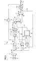
- FIG. 1 shows a block diagram of a control circuit.
- a value for a control deviation 25 is formed from a setpoint value 2 and an actual value 4 as an output signal 80 and fed to the further block 5. If the controller has an inverse effect, the signs must be exchanged.
- the output signal 80 of the subtracting block 3 is forwarded to an input of the further block 5.
- the further module 5 has a further input which is connected to an output of a memory module 6.
- a value is stored, which is forwarded as an output signal to the other module 5.
- the value stored in memory module 6 is also referred to as constant K P.
- the further module 5 is designed such that the value of the control deviation 25 is multiplied by the value stored in the memory module 6 and is forwarded as the output signal 59 to a first input 61 of a switching-addition module 60.
- the output signal 80 is also forwarded to an integral increment module 9 where it is multiplied by a value 10 and forwarded as the output signal 71 to the switching-addition module 60.
- the value 10 is formed from the quotient with a cycle time ⁇ T and an integral time T N of an integrator.
- the shift addition module 60 has four inputs: The first input 61 for the output signal 59 of the other Block 5, a second input 62 for an output signal 71 of the integral increment module 9, a third input 63 for a switching signal 21 from a switching block 12 and a fourth input 64 for a at an output 82 of a Minimum-maximum limiter 14 applied manipulated variable signal 15.
- the switching module 12 has three inputs 65, 66, 67 on. At the input 67 is the output signal 80 of Subtracting block 3 on, at input 65 is a Controller output signal 23 on and at the input 66 is the Manipulated variable signal 15 on. The mode of action of the switching module 12 is described in FIG.
- An output signal 68 of the switching-addition module 60 is located at an input 81 of the minimum-maximum limiter 14 at.
- the shift addition module 60 is such trained to be between a first state at the the output signal 59 of the further module 5 for calculation of the manipulated variable signal 15 is added and a second State in which changes of the output signal 59 of the further block 5 are blocked, can be switched.
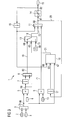
- FIG. 2 is a block diagram of a control circuit with representation of a proportional and Integral component shown.
- the switchover addition module 60 includes a switching module in this embodiment 13 and an addition module 11.
- the switching module 13 has the third input 63 and the fourth input 64.
- the addition module 11 has the second input 62 and a fifth input 72 which is provided with an output signal 18 of the switching block 13 is connected.
- the first entrance 61 and the fourth input 64 are at an adder 8th provided, which provides an output signal 83, which at a sixth input 69 of the switching module 13 is present.
- the output signal 59 is formed, which is referred to as another part of the calculation the manipulated variable signal 15 is used.
- This further Share is in this case a proportional share.
- the manipulated variable signal 15 is forwarded via a first latch block 16 to the adder block 8 and is also referred to as Confirmed signal Y Re.
- the regulator output signal 23, which is connected to the input 81 of the Minimum-maximum limiter 14 is applied via a second Buffer module 17 to the switching module 12th forwarded.
- the output signal 80 of the subtractor 3 is applied the input 67 of the switching module 12 at.
- the switching module 12 is described in more detail in FIG.
- the Output signal 18 is located at the fifth input 72 of the adder module 11 and is there with the output signal 71 of Integral increment module 9 multiplied.
- At one Output of the adder 11 is the Controller output signal 23 on.
- the regulator output signal 23 becomes limited by the minimum-maximum limiter 14 and is located subsequently as a manipulated variable signal 15.
- An output of the switching component 12 is located at the third input 63 of the switching module 13 at. That from the first Buffer module 16 incoming signal is on the fourth Input 64 of the switching module 13 and at the input 66 of Switching block 12 on.
- the function of the switching module 13 depends on the output of the switching module 12. In one Unlimited operation has the switching module 13 in the Figure 2 described position. Supplies the switching module 12th a switching signal 21 with a logical value 1, changes the function of the switching block 13 as follows: the Output signal 18 is no longer via a line 19 am sixth input 69, but via a line 20 on the fourth Input 64 formed.
- the switching component 12 delivers a switching signal 21 with a logical value 1, then the change in the further component which is applied as an output signal 59 to the further component 5 is neglected.
- the new controller output signal 23 is formed in the adder 11 by the addition of the output signal 71 of the integral increment module 9 with the signal Y return from the first buffer memory block 16.
- the controller output signal 23 by a controller subroutine or externally z. B. limited by a minimum or maximum selection with output signals of other controller.
- FIG. 3 shows a further embodiment of the control circuit.
- a signal is forwarded directly to the addition module 11 after the first buffer module 16.
- the addition component 11 now has a further input which is connected to the first intermediate memory component 16.
- the adder module 8 shown in FIG. 3 now has only two inputs, in contrast to the embodiment of the adder module 8 shown in FIG. This leads to the advantage that the manipulated variable signal 15 according to FIG. 3 rests directly above the first intermediate memory component 16 on the addition component 11 and the manipulated variable signal 15 is applied to the addition component 11 independently of the switching component 13.
- the switching module 13 has a seventh input 73, at which a signal is applied, which corresponds to the value zero.
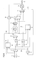
- the switching module 12 is shown in more detail.
- the core idea here is to switch the structure of the controller with active limitation depending on the control deviation 25.
- the switching signal 21 of the switching module 12 can assume a value which corresponds to a logic value of one or zero.
- the manipulated variable signal 15 is compared with the controller output signal 23 in the block 24.
- the value of the control deviation 25 is compared in block 26 with a predefinable positive control limit value X w, positive 27. If the manipulated variable signal 15 is smaller than the controller output signal 23 and the value of the control deviation 25 is greater than or equal to the positive control limit value X w, positive 27, then the switching signal 21 corresponds to a logic value 1.
- the manipulated variable signal 15 is also sent to the module 28 in FIG a negative limit is taken into account. Also to the block 28, the controller output signal 23 is passed. The value of the control deviation 25 is compared in block 29 with a predefinable negative limit value X w, negative 30. If the manipulated variable signal 15 is greater than the controller output signal 23 and the value of the control deviation 25 is less than or equal to the negative control limit value X w, negative 30, a switching signal 21 is formed via an AND component 31 and an OR component 32, which is a logical Value equals one.
- control circuit be formed such that an inverse Impact is possible.
- the output signal is included increasing setpoint. This is achieved by swapping the Inputs to the subtractor 3 and the adder 46th
- the first Buffer module 16 with an external signal generator connected.
- About the external signal generator are via minimum and Maximum selections, other controls or others Signals taken into account.
- FIG. 5 shows a further embodiment of the switching module 12.
- FIG. 5 contains further components which make it possible to take into account noise of the control deviation 25.
- the value of the control deviation 25 is applied to a block 35 via a further buffer block 33 and a block 34.
- a change in the value of the control deviation 25 is compared with a predefinable limit value ⁇ X w, positive 36. If the condition occurs that the change in the value of the system deviation 25 is greater than the limit value ⁇ X w, positive 36, a logic signal is forwarded to the module 37.
- the block 37 is an AND block.
- a second signal, which is processed in the block 37 comes from the block 24 and provides a signal for an upper limit.
- the change in the value of the control deviation 25 is also forwarded to the block 38.
- the change in the value of the control deviation 25 is compared with a predefinable negative limit value ⁇ X w, negative 39. If the change in the value of the control deviation 25 is smaller than the limit value ⁇ X w, negative 39, then a value which corresponds to a logic value 1 is forwarded to the module 40.
- the module 40 is an AND component. For this block 40, the signal is passed, which comes from the block 28. If both signals with a value corresponding to a logical value of 1 arrived to the block 40, then a value corresponding to a logic value of 1 is forwarded to the block 41.
- the block 41 is an OR block, which is comparable to the block 32 of FIG.
- the OR block 41 now has 4 inputs, which come from the blocks 42, 31, 37 and 40.
- the illustrated latch 33 may also be a higher order latch or any discrete filter, delay element, or deadtime element.
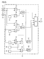
- Embodiments of the control circuit has the further Share a proportional share.
- FIG 6 is a further advantageous embodiment of the control circuit represented, with the remaining share now the Proportional and a differential component has.
- a differential component block 42 is a value for the Differential component from the setpoint 2, the actual value 4, the Manipulated variable signal 15 and the controller output signal 23 is formed and to an adder block 43 as an output signal 19 forwarded.
- the calculation of the differential component is carried out according to those described in the prior art Procedures.
- the output signal 19 of the Differential component block 42 and the further block 5 added to an output signal 44 and the third Buffer module 7 to the adder 8th forwarded and from there via the switching module 13 at the adder module 11 continued.
- the further part now has a differential part and a proportional component.
- FIG. 7 shows an embodiment of the invention Differential component 42.
- the setpoint 2 and the Actual value 4 are forwarded to an adder 46. After the adder module 46, a signal arrives at a Switching block 47. The actual value 4 is also directly to Switching block 47 forwarded. In an alternative Embodiment, the actual value 4 with a factor -1 multiplied before the resulting inverted signal into the switching module 47 passes. About the switching module 47 it is possible to change the setpoint 2 for Calculation of the differential component.
- the block 58 With the block 58 is provided with an output signal 74 of Switching block 47 a value to an input 75 of a Multiplying module 50 forwarded.
- the module 58 is not a delay block, but a so-called DT1 element. It filters and differentiates to some extent simultaneously.
- the multiplication device 50 has a second input 76.
- the manipulated variable signal 15 and the controller output signal 23 is compared in comparison block 52.
- the comparison module 52 provides an output signal 77 to a switching device 53 is forwarded. If the values of the Controller output signal 23 and the manipulated variable signal 15 equal are the comparison block 52 provides a logical value 1 as an output signal 77 and otherwise a logical value Zero.
- the switching module 53 has one with the value Zero contained memory chip 57 connected first Input 78 and one with a value for a derivative time 84 contained second memory device 56 connected second Input 79 on.
- An output signal 54 is located at an input 85 of a slope limiting block 55 at.
Landscapes
- Physics & Mathematics (AREA)
- General Physics & Mathematics (AREA)
- Engineering & Computer Science (AREA)
- Automation & Control Theory (AREA)
- Feedback Control In General (AREA)
Abstract
Description
- der mit dem Regelalgorithmus berechnete Wert für die Stellgröße ist größer als der Wert, der nach dem Minimum-Maximum-Begrenzer begrenzt wird und
- eine Regelabweichung, die aus der Differenz zwischen dem Sollwert und der Regelgröße ermittelt wird, ist größer oder gleich einem vorgebbaren Grenzwert Xw,positiv oder
- der mit dem Regelalgorithmus berechnete Wert für die Stellgröße ist kleiner als der Wert, der nach dem Minimum-Maximum-Begrenzer begrenzt wird und
- die Regelabweichung ist kleiner oder gleich einem vorgebbaren Grenzwert Xw,negativ.
- Signal wurde nach oben begrenzt und
- eine Änderung der Regelabweichung e ist größer als ein vorgebbarer Grenzwert Δ Xw,positiv oder
- Signal wurde nach unten begrenzt und
- eine Änderung der Regelabweichung e ist kleiner als ein vorgebbarer Grenzwert Δ Xw,negativ.
einen zweiten Eingang für das Ausgangssignal des Integral-Inkrement-Bausteins,
einen dritten Eingang für ein Schaltsignal und
einen vierten Eingang für ein Signal aus einem Minimum-Maximum-Begrenzer, der zur Begrenzung des Wertes für die Stellgröße auf einen voreingestellten Wert ausgebildet ist, wobei der Umschalt-Additions-Baustein zum Berechnen eines Wertes für die Stellgröße als Ausgangssignal aufgrund des weiteren Bausteins, dem Ausgangssignal des Integral-Inkrement-Baustein und des Signals aus dem Minimum-Maximum-Begrenzers ausgebildet ist, wobei der Umschalt-Additions-Baustein zwischen einem ersten Zustand, bei dem das Ausgangssignal des weiteren Bausteins zur Berechnung der Stellgröße addiert wird und einem zweiten Zustand, bei dem das Ausgangssignal des weiteren Bausteins geblockt wird, umschaltbar ist, und einen Schalt-Baustein zum Erzeugen des Schaltsignals für den Umschalt-Additions-Bausteins, wobei der Schalt-Baustein derart ausgebildet ist, dass ein Schaltsignal zum Umschalten in den zweiten Zustand an den Umschalt-Additions-Baustein gesendet wird, wenn der Wert der Stellgröße größer als der nach dem Minimum-Maximum-Begrenzer voreingestellten Wert ist und die Regelabweichung größer oder gleich einem vorgebbaren Grenzwert Xw,positiv ist oder wenn der Wert der Stellgröße kleiner als der nach dem Minimum-Maximum-Begrenzer voreingestellte Wert ist und die Regelabweichung kleiner oder gleich einem vorgebbaren Grenzwert Xw,negativ ist. Die Vorteile ergeben sich entsprechend der Beschreibung zur Lösung des Verfahrens.
- Figur 1
- Blockschaltbild eines Regel-Schaltkreises
- Figur 2
- ein Blockschaltbild eines Regel-Schaltkreises mit Darstellung eines Proportional- und Integralanteils;
- Figur 3
- eine weitere Ausführungsform des Regel-Schaltkreises;
- Figur 4
- ein Blockschaltbild mit Darstellung einer Umschaltlogik;
- Figur 5
- ein Blockschaltbild mit Darstellung einer Grenzwertstabilisierung;
- Figur 6
- ein Blockschaltbild mit Differentialanteil-Baustein;
- Figur 7
- ein Blockschaltbild mit Darstellung einer zeitdiskreten Differentation;
In der Figur 4 ist der Schalt-Baustein 12 näher dargestellt. Kerngedanke ist hierbei, in Abhängigkeit von der Regelabweichung 25 die Struktur des Reglers bei aktiver Begrenzung umzuschalten. Das Schaltsignal 21 des Schalt-Bausteins 12 kann einen Wert annehmen, der einem logischen Wert eins oder Null entspricht. Das Stellgrößensignal 15 wird mit dem Reglerausgangssignal 23 im Baustein 24 verglichen. Der Wert der Regelabweichung 25 wird im Baustein 26 mit einem vorgebbaren positiven Regelgrenzwert Xw,positiv 27 verglichen. Ist das Stellgrößensignal 15 kleiner als das Reglerausgangssignal 23 und ist der Wert der Regelabweichung 25 größer oder gleich dem positiven Regelgrenzwert Xw,positiv 27, so entspricht das Schaltsignal 21 einem logischen Wert 1. Das Stellgrößensignal 15 wird auch an den Baustein 28, in dem eine negative Begrenzung berücksichtigt wird, weitergeleitet. Ebenfalls zum Baustein 28 wird das Reglerausgangssignal 23 geleitet. Der Wert der Regelabweichung 25 wird im Baustein 29 mit einem vorgebbaren negativen Grenzwert Xw,negativ 30 verglichen. Ist das Stellgrößensignal 15 größer als das Reglerausgangssignal 23 und ist der Wert der Regelabweichung 25 kleiner oder gleich dem negativen Regelgrenzwert Xw,negativ 30, so wird über einen Und-Baustein 31 und einem Oder-Baustein 32 ein Schaltsignal 21 gebildet, das einem logischen Wert eins entspricht.
Claims (25)
- Verfahren zur Regelung einer Regelgröße, die über ein Stellgrößensignal (15) veränderbar ist, die in Abhängigkeit eines Sollwertes (2) und eines Istwertes (4) für die Regelgröße mit einem Regelalgorithmus berechnet wird, der einen Integralanteil und einen weiteren Anteil aufweist, wobei das Stellgrößensignal (15), der Integralanteil und der weitere Anteil mit dem Regelalgorithmus berechnet werden,
dadurch gekennzeichnet,dass der Wert des Stellgrößensignals (15) zuerst mit dem Regelalgorithmus berechnet wird und nach einem Minimum-Maximum-Begrenzer (14) begrenzt und an den Regelalgorithmus zurückgemeldet wird,
wobei eine Änderung des weiteren Anteils vernachlässigt wird, wenn folgende Bedingungen eintreten:der mit dem Regelalgorithmus berechnete Wert für das Stellgrößensignal (15) ist größer als der Wert, der nach dem Minimum-Maximum-Begrenzer (14) begrenzt wird undeine Regelabweichung (25), die aus der Differenz zwischen dem Sollwert (2) und dem Istwert (4) der Regelgröße ermittelt wird, ist größer oder gleich einem vorgebbaren Grenzwert Xw,positiv
oderder mit dem Regelalgorithmus berechnete Wert für das Stellgrößensignal (15) ist kleiner als der Wert, der nach dem Minimum-Maximum-Begrenzer (14) begrenzt wird unddie Regelabweichung (25) ist kleiner oder gleich einem vorgebbaren Grenzwert Xw,negativ. - Verfahren nach Anspruch 1,
dadurch gekennzeichnet,dass
der weitere Anteil ein Proportionalanteil ist. - Verfahren nach Anspruch 1 oder 2,
dadurch gekennzeichnet, dass
der Regelalgorithmus einen Differenzialanteil aufweist. - Verfahren nach einem der Ansprüche 1 bis 3,
dadurch gekennzeichnet, dass
der Differenzialanteil zum weiteren Anteil addiert wird. - Verfahren nach einem der Ansprüche 1 bis 4,
dadurch gekennzeichnet, dass
der weitere Anteil vernachlässigt wird, wenn folgende Bedingung zusätzlich eintritt:Signal wurde nach oben begrenzt undeine Änderung der Regelabweichung (25) ist größer als ein vorgebbarer Grenzwert Δ Xw,positiv
oderSignal wurde nach unten begrenzt undeine Änderung der Regelabweichung (25) ist kleiner als ein vorgebbarer Grenzwert Δ Xw,negativ . - Verfahren nach einem der Ansprüche 3 bis 5,
dadurch gekennzeichnet, dass
Änderungen des Sollwertes (2) zur Berechnung des Differentialanteils berücksichtigt werden können. - Verfahren nach einem der Ansprüche 3 bis 6,
dadurch gekennzeichnet, dass
der Differentialanteil mit einer einstellbaren Zeitkonstanten gefiltert wird. - Verwendung des Verfahrens nach einem der Ansprüche 1 bis 7 für den Betrieb eines Verdichters.
- Vorrichtung zur Regelung einer Regelgröße, die über ein Stellgrößensignal (15) veränderbar ist, mit einem Subtrahier-Baustein (3) zur Berechnung einer Regelabweichung (25) durch Subtrahieren eines Sollwertes (2) der Regelgröße von einem Istwert (4) der Regelgröße,
einem Integral-Inkrement-Baustein (9) zum Berechnen eines Integral-Inkrement-Anteils für das Stellgrößensignal (15) als Ausgangssignal aufgrund der Regelabweichung (25),
einem weiteren Baustein (5) zum Berechnen eines weiteren Anteils für das Stellgrößensignal (15) als Ausgangssignal aufgrund der Regelabweichung (25),
gekennzeichnet durch
einen Umschalt-Additions-Baustein (60),
der einen ersten Eingang (61) für das Ausgangssignal (70) des weiteren Bausteins (5),
einen zweiten Eingang (62) für das Ausgangssignal (71) des Integral-Inkrement-Bausteins (9),
einen dritten Eingang (63) für ein Schaltsignal (21) und einen vierten Eingang (64) für ein Signal aus einem Minimum-Maximum-Begrenzer (14), der zur Begrenzung des Wertes für das Stellgrößensignal (15) auf einen voreingestellten Wert ausgebildet ist, aufweist und
zum Berechnen eines Wertes für die Stellgröße (15) als Ausgangssignal aufgrund des weiteren Bausteins (5), dem Ausgangssignal des Integral-Inkrement-Baustein (9) und des Signals (22) aus dem Minimum-Maximum-Begrenzers (14) ausgebildet ist,
wobei der Umschalt-Additions-Baustein (60) zwischen einem ersten Zustand, bei dem das Ausgangssignal (70) des weiteren Bausteins (5) zur Berechnung des Stellgrößensignals (15) addiert wird und einem zweiten Zustand, bei dem das Ausgangssignal (70) des weiteren Bausteins (5) geblockt wird, umschaltbar ist,
und
einen Schalt-Baustein (12) zum Erzeugen des Schaltsignals (21) für den Umschalt-Additions-Baustein (60), wobei der Schalt-Baustein (12) derart ausgebildet ist,
dass ein Schaltsignal (21) zum Umschalten in den zweiten Zustand an den Umschalt-Additions-Baustein (60) gesendet wird, wenn der Wert des Stellgrößensignals (15) größer als der nach dem Minimum-Maximum-Begrenzer (14) voreingestellte Wert ist und die Regelabweichung (25) größer oder gleich einem vorgebbaren Grenzwert Xw,positiv ist
oder
wenn der Wert des Stellgrößensignals (15) kleiner als der nach dem Minimum-Maximum-Begrenzer (14) voreingestellte Wert ist und die Regelabweichung (25) kleiner oder gleich einem vorgebbaren Grenzwert Xw,negativ ist. - Vorrichtung nach Anspruch 9,
dadurch gekennzeichnet, dass
der Schall-Baustein (12) derart ausgebildet ist, dass ein Schaltsignal (21) vom Schall-Baustein (12) an den Umschalt-Additions-Baustein (60) gesendet wird, wenn der Wert des Stellgrößensignals (15) größer als der nach dem Minimum-Maximum-Begrenzer (14) eingestellte Wert ist
und
eine Änderung der Regelabweichung (25) größer einem vorgebbaren Grenzwert Δ Xw,positiv ist
oder
der Wert des Stellgrößensignals (15) kleiner als der nach dem Minimum-Maximum-Begrenzer (14) eingestellte Wert ist
und
eine Änderung der Regelabweichung (25) kleiner einem vorgebbaren Grenzwert Δ Xw,negativ ist. - Vorrichtung nach Anspruch 9 oder 10,
dadurch gekennzeichnet, dass
der Umschalt-Additions-Baustein (60) einen Umschalt-Baustein (13) mit dem ersten (61), dritten (63) und vierten (64) Eingang und einen Additions-Baustein (11) mit dem zweiten Eingang (62) und einen fünften Eingang (72) für ein Ausgangssignal (18) des Umschalt-Bausteins (13) umfasst. - Vorrichtung nach Anspruch 11,
dadurch gekennzeichnet, dass
der Umschalt-Baustein (13),
der erste (61) und vierte Eingang (64) zu einem sechsten Eingang (69) für ein Signal zusammengefasst ist, das aus der Summe des Ausgangssignals des weiteren Bausteins (5) und des Signals aus dem Minimum-Maximum-Begrenzer (14) gebildet ist,
den für den vierten Eingang (64) für das Signal aus dem Minimum-Maximum-Begrenzer (14) und den dritten Eingang (63) für das Schaltsignal (21) aufweist,
sowie
zwischen einem ersten Zustand, bei dem nur das Signal am sechsten Eingang (69) als Ausgangssignal (18) durchgeleitet wird und einem zweiten Zustand, bei dem nur das Signal am vierten Eingang (64) als Ausgangssignal (18) durchgeleitet wird, umschaltbar ist. - Vorrichtung nach Anspruch 12,
dadurch gekennzeichnet, dass
der Additions-Baustein (11) ausgebildet ist zum Addieren des Ausgangssignals (18) des Umschalt-Bausteins (13) und des Ausgangssignals (71) des Integral-Inkrement-Bausteins (9) zu einem Ausgangssignal. - Vorrichtung nach Anspruch 9 oder 10,
dadurch gekennzeichnet, dass
der Umschalt-Additions-Baustein (60) einen Umschalt-Baustein (13) mit dem ersten (61) und dritten (63) Eingang und einen Additions-Baustein (11) mit dem zweiten (62), vierten (64) Eingang und den fünften Eingang (72) für das Ausgangssignal (18) des Umschalt-Bausteins (13) umfasst. - Vorrichtung nach Anspruch 14,
dadurch gekennzeichnet, dass
der Umschalt-Baustein (13)
einen siebten Eingang (73) für ein den Wert 0 aufweisendes Signal aufweist
sowie
zwischen einem ersten Zustand, bei dem das Ausgangssignal (59) des weiteren Bausteins als Ausgangssignal (18) durchgeleitet wird und
einem zweiten Zustand, bei dem das den Wert 0 aufweisende Signal durchgeleitet wird, umschaltbar ist. - Vorrichtung nach Anspruch 15,
dadurch gekennzeichnet, dass
der Additions-Baustein (11) ausgebildet ist zum Addieren des Ausgangssignals (18) des Umschalt-Bausteins (13), des Ausgangssignals (71) des Integral-Inkrement-Bausteins (9) und des Signals aus dem Minimum-Maximum-Begrenzers (14) zu einem Ausgangssignal (68). - Vorrichtung nach einem der Ansprüche 9 bis 16,
dadurch gekennzeichnet, dass
der weitere Baustein (5) einen Proportional-Anteil-Baustein und einen Differentialanteil-Baustein (42) umfasst. - Vorrichtung nach Anspruch 17,
dadurch gekennzeichnet, dass
der Differenzialanteil-Baustein (42) zum Berechnen eines Differenzialanteils für das Stellgrößensignal (15) als Ausgangssignal aufgrund
der Regelabweichung (25),
des Signals (22) aus dem Minimum-Maximum-Begrenzer (14) und
eines Ausgangsignals (23) des Additions-Bausteines (11) vorgesehen ist. - Vorrichtung nach Anspruch 17 oder 18,
dadurch gekennzeichnet, dass
der Proportionalanteil-Baustein (5) zum Berechnen eines Proportionalanteils für das Stellgrößensignal (15) als Ausgangssignal aufgrund der Regelabweichung (25) vorgesehen ist. - Vorrichtung nach einem der Ansprüche 16 bis 19,
dadurch gekennzeichnet, dass
ein Additionsbaustein (11) zum Addieren des Ausgangssignals des Differentialanteil-Bausteins (42) und des Ausgangssignals des Proportionalanteil-Bausteins (5) als Ausgangssignal für den weiteren Anteil vorgesehen ist. - Vorrichtung nach einem der Ansprüche 16 oder 20,
dadurch gekennzeichnet, dass
der Differenzialanteil-Baustein (42) einen Umschalt-Baustein (13) aufweist, der
einen ersten Eingang für den Wert der Regelgröße und
einen zweiten Eingang für den Wert der Regelabweichung (25) aufweist
sowie
zwischen einem ersten Zustand, bei dem die Änderung des Sollwertes (2) durchgeleitet wird und einem zweiten Zustand, bei dem nur die Regelabweichung (25) weitergeleitet wird, umschaltbar ist. - Vorrichtung nach einem der Ansprüche 9 bis 21,
dadurch gekennzeichnet, dass
der Differenzialanteil-Baustein (42) einen Verzögerungs-Baustein (48) zum Berechnen des Differentialanteils aufweist. - Vorrichtung nach einem der Ansprüche 9 bis 22,
dadurch gekennzeichnet, dass
ein erster Zwischenspeicher-Baustein (16) zum Zwischenspeichern eines Signals als Ausgangssignal vorgesehen ist,
der mit dem nach dem Minimum-Maximum-Begrenzer (14) vorhandenen Signal verbunden ist und
das Ausgangssignal des ersten Zwischenspeicher-Bausteins (16) mit dem Umschalt-Addier-Baustein (60) oder mit dem Addier-Baustein (11) verbunden ist. - Vorrichtung nach einem der Ansprüche 9 bis 23
dadurch gekennzeichnet, dass
ein zweiter Zwischenspeicher-Baustein (17) zum Zwischenspeichern eines Signals als Ausgangssignal vorgesehen ist,
der mit dem Ausgangsignals des Additions-Bausteins (11) verbunden ist und
das Ausgangssignal des Zwischenspeicher-Bausteins (17) mit dem Schalt-Baustein (12) verbunden ist. - Vorrichtung nach einem der Ansprüche 9 bis 24,
dadurch gekennzeichnet, dass
ein dritter Zwischenspeicher-Baustein (7) zum Zwischenspeichern eines Signals als Ausgangssignal vorgesehen ist,
der mit dem Ausgangssignal des weiteren Bausteins (5) verbunden ist und
das Ausgangssignal des weiteren Zwischenspeicher-Bausteins mit dem ersten Eingang (61) des Umschalt-Additions-Bausteins (60) verbunden ist.
Priority Applications (1)
| Application Number | Priority Date | Filing Date | Title |
|---|---|---|---|
| EP03020210.5A EP1513033B1 (de) | 2003-09-05 | 2003-09-05 | Verfahren und Vorrichtung zur Regelung einer Regelgrösse |
Applications Claiming Priority (1)
| Application Number | Priority Date | Filing Date | Title |
|---|---|---|---|
| EP03020210.5A EP1513033B1 (de) | 2003-09-05 | 2003-09-05 | Verfahren und Vorrichtung zur Regelung einer Regelgrösse |
Publications (2)
| Publication Number | Publication Date |
|---|---|
| EP1513033A1 true EP1513033A1 (de) | 2005-03-09 |
| EP1513033B1 EP1513033B1 (de) | 2016-08-31 |
Family
ID=34130156
Family Applications (1)
| Application Number | Title | Priority Date | Filing Date |
|---|---|---|---|
| EP03020210.5A Expired - Lifetime EP1513033B1 (de) | 2003-09-05 | 2003-09-05 | Verfahren und Vorrichtung zur Regelung einer Regelgrösse |
Country Status (1)
| Country | Link |
|---|---|
| EP (1) | EP1513033B1 (de) |
Citations (4)
| Publication number | Priority date | Publication date | Assignee | Title |
|---|---|---|---|---|
| EP0533148A1 (de) * | 1991-09-18 | 1993-03-24 | Samsung Electronics Co., Ltd. | Begrenzerschaltung für Servomotor Steuervorrichtung |
| US5270916A (en) * | 1990-02-27 | 1993-12-14 | Ge Fanuc Automation North America, Inc. | Apparatus and method for preventing runaway of the integral term of a proportional plus integral controller |
| US5298845A (en) * | 1991-10-31 | 1994-03-29 | Johnson Service Company | Anti-windup proportional plus integral controller |
| US5303142A (en) * | 1989-10-06 | 1994-04-12 | United Technologies Corporation | Control system for gas turbine helicopter engines and the like |
-
2003
- 2003-09-05 EP EP03020210.5A patent/EP1513033B1/de not_active Expired - Lifetime
Patent Citations (4)
| Publication number | Priority date | Publication date | Assignee | Title |
|---|---|---|---|---|
| US5303142A (en) * | 1989-10-06 | 1994-04-12 | United Technologies Corporation | Control system for gas turbine helicopter engines and the like |
| US5270916A (en) * | 1990-02-27 | 1993-12-14 | Ge Fanuc Automation North America, Inc. | Apparatus and method for preventing runaway of the integral term of a proportional plus integral controller |
| EP0533148A1 (de) * | 1991-09-18 | 1993-03-24 | Samsung Electronics Co., Ltd. | Begrenzerschaltung für Servomotor Steuervorrichtung |
| US5298845A (en) * | 1991-10-31 | 1994-03-29 | Johnson Service Company | Anti-windup proportional plus integral controller |
Non-Patent Citations (1)
| Title |
|---|
| LEHRBUCH: "Regelungstechnik-ein praxisorientiertes Lehrbuch", VERLAG HARRI DEUTSCH |
Also Published As
| Publication number | Publication date |
|---|---|
| EP1513033B1 (de) | 2016-08-31 |
Similar Documents
| Publication | Publication Date | Title |
|---|---|---|
| DE68926600T2 (de) | Digitales Regelsystem | |
| EP0132487B1 (de) | Verfahren zum Regeln von mindestens zwei parallel geschalteten Turbokompressoren | |
| DE112013007679B4 (de) | Numerische Steuerungsanlage und numerisches Steuerungsverfahren | |
| DE4104642C2 (de) | PID- bzw. PI-Regler | |
| DE2347741A1 (de) | Prozessregelorgan mit selbsttaetiger anpassung an unbekannte oder veraenderliche parameter | |
| DE69007874T2 (de) | Regelungsanordnung für ein Verfahrensinstrumentierungssystem. | |
| WO2000022487A1 (de) | Regeleinrichtung zur regelung einer strecke mit mehreren verkoppelten regelgrössen | |
| EP0473914B1 (de) | System zur Regelung eines Stellwerks in einem Kraftfahrzeug | |
| DE102018206114A1 (de) | Verfahren zum Ansteuern eines Ventils und entsprechende Vorrichtung | |
| EP3507656B1 (de) | Regelvorrichtung mit einstellbarkeit des regelverhaltens | |
| DE4418997C2 (de) | Feldorientierte Regelung für einen über einen Spannungs-Pulswechselrichter gespeisten Drehstrommotor | |
| EP3438773A1 (de) | Bearbeitung von werkstücken mit modellgestützter fehlerkompensation | |
| EP0752630A1 (de) | Selbsteinstellbare Regeleinrichtung und Verfahren zur Selbsteinstellung dieses Reglers | |
| DE102014003084A1 (de) | Digitalhydraulisches Antriebssystem | |
| EP1513033B1 (de) | Verfahren und Vorrichtung zur Regelung einer Regelgrösse | |
| WO2019048246A1 (de) | Automatische bewertung eines maschinenverhaltens | |
| DE69114623T2 (de) | Regelungssystem des Typs mit zwei Freiheitsgraden. | |
| EP1229411B1 (de) | Steuerungsverfahren sowie Regelungsstruktur zur Bewegungsführung, Vorsteuerung und Feininterpolation von Objekten in einem Drehzahlreglertakt, der schneller als der Lagereglertakt ist | |
| DE2343511C2 (de) | Regelungseinrichtung mit selbsttätiger Adaption der Reglerparameter | |
| DE69330976T2 (de) | Regelungsmethode zur Erreichung eines Sollwertes | |
| DE2638456C3 (de) | Verfahren zum Anfahren von Regelkreisen | |
| DE10055166C5 (de) | Verfahren zur Regelung der Leistung und Drehzahl einer Turbine | |
| EP2482147B1 (de) | Verfahren zur Anpassung der Taktfrequenz eines Mikroprozessors einer industriellen Automatisierungskomponente, und Automatisierungskomponente mit einem Mikroprozessor mit veränderlicher Taktfrequenz | |
| DE102007062173A1 (de) | Verfahren zum Betreiben einer Brennkraftmaschine und Steuer- oder Regelrichtung für eine Brennkraftmaschine | |
| DE4333804C2 (de) | Regeleinrichtung |
Legal Events
| Date | Code | Title | Description |
|---|---|---|---|
| PUAI | Public reference made under article 153(3) epc to a published international application that has entered the european phase |
Free format text: ORIGINAL CODE: 0009012 |
|
| AK | Designated contracting states |
Kind code of ref document: A1 Designated state(s): AT BE BG CH CY CZ DE DK EE ES FI FR GB GR HU IE IT LI LU MC NL PT RO SE SI SK TR |
|
| AX | Request for extension of the european patent |
Extension state: AL LT LV MK |
|
| 17P | Request for examination filed |
Effective date: 20050404 |
|
| AKX | Designation fees paid |
Designated state(s): AT BE BG CH CY CZ DE DK EE ES FI FR GB GR HU IE IT LI LU MC NL PT RO SE SI SK TR |
|
| 17Q | First examination report despatched |
Effective date: 20110131 |
|
| RAP1 | Party data changed (applicant data changed or rights of an application transferred) |
Owner name: SIEMENS AKTIENGESELLSCHAFT |
|
| RAP1 | Party data changed (applicant data changed or rights of an application transferred) |
Owner name: SIEMENS AKTIENGESELLSCHAFT |
|
| GRAP | Despatch of communication of intention to grant a patent |
Free format text: ORIGINAL CODE: EPIDOSNIGR1 |
|
| INTG | Intention to grant announced |
Effective date: 20160323 |
|
| GRAS | Grant fee paid |
Free format text: ORIGINAL CODE: EPIDOSNIGR3 |
|
| GRAA | (expected) grant |
Free format text: ORIGINAL CODE: 0009210 |
|
| AK | Designated contracting states |
Kind code of ref document: B1 Designated state(s): AT BE BG CH CY CZ DE DK EE ES FI FR GB GR HU IE IT LI LU MC NL PT RO SE SI SK TR |
|
| REG | Reference to a national code |
Ref country code: CH Ref legal event code: EP Ref country code: CH Ref legal event code: NV Representative=s name: SIEMENS SCHWEIZ AG, CH Ref country code: GB Ref legal event code: FG4D Free format text: NOT ENGLISH |
|
| REG | Reference to a national code |
Ref country code: IE Ref legal event code: FG4D Free format text: LANGUAGE OF EP DOCUMENT: GERMAN |
|
| REG | Reference to a national code |
Ref country code: DE Ref legal event code: R096 Ref document number: 50315530 Country of ref document: DE |
|
| REG | Reference to a national code |
Ref country code: AT Ref legal event code: REF Ref document number: 825493 Country of ref document: AT Kind code of ref document: T Effective date: 20161015 |
|
| REG | Reference to a national code |
Ref country code: NL Ref legal event code: FP |
|
| PG25 | Lapsed in a contracting state [announced via postgrant information from national office to epo] |
Ref country code: FI Free format text: LAPSE BECAUSE OF FAILURE TO SUBMIT A TRANSLATION OF THE DESCRIPTION OR TO PAY THE FEE WITHIN THE PRESCRIBED TIME-LIMIT Effective date: 20160831 |
|
| PG25 | Lapsed in a contracting state [announced via postgrant information from national office to epo] |
Ref country code: GR Free format text: LAPSE BECAUSE OF FAILURE TO SUBMIT A TRANSLATION OF THE DESCRIPTION OR TO PAY THE FEE WITHIN THE PRESCRIBED TIME-LIMIT Effective date: 20161201 Ref country code: BE Free format text: LAPSE BECAUSE OF NON-PAYMENT OF DUE FEES Effective date: 20160930 Ref country code: ES Free format text: LAPSE BECAUSE OF FAILURE TO SUBMIT A TRANSLATION OF THE DESCRIPTION OR TO PAY THE FEE WITHIN THE PRESCRIBED TIME-LIMIT Effective date: 20160831 Ref country code: SE Free format text: LAPSE BECAUSE OF FAILURE TO SUBMIT A TRANSLATION OF THE DESCRIPTION OR TO PAY THE FEE WITHIN THE PRESCRIBED TIME-LIMIT Effective date: 20160831 |
|
| PG25 | Lapsed in a contracting state [announced via postgrant information from national office to epo] |
Ref country code: EE Free format text: LAPSE BECAUSE OF FAILURE TO SUBMIT A TRANSLATION OF THE DESCRIPTION OR TO PAY THE FEE WITHIN THE PRESCRIBED TIME-LIMIT Effective date: 20160831 Ref country code: RO Free format text: LAPSE BECAUSE OF FAILURE TO SUBMIT A TRANSLATION OF THE DESCRIPTION OR TO PAY THE FEE WITHIN THE PRESCRIBED TIME-LIMIT Effective date: 20160831 |
|
| PG25 | Lapsed in a contracting state [announced via postgrant information from national office to epo] |
Ref country code: DK Free format text: LAPSE BECAUSE OF FAILURE TO SUBMIT A TRANSLATION OF THE DESCRIPTION OR TO PAY THE FEE WITHIN THE PRESCRIBED TIME-LIMIT Effective date: 20160831 Ref country code: CZ Free format text: LAPSE BECAUSE OF FAILURE TO SUBMIT A TRANSLATION OF THE DESCRIPTION OR TO PAY THE FEE WITHIN THE PRESCRIBED TIME-LIMIT Effective date: 20160831 Ref country code: SK Free format text: LAPSE BECAUSE OF FAILURE TO SUBMIT A TRANSLATION OF THE DESCRIPTION OR TO PAY THE FEE WITHIN THE PRESCRIBED TIME-LIMIT Effective date: 20160831 Ref country code: PT Free format text: LAPSE BECAUSE OF FAILURE TO SUBMIT A TRANSLATION OF THE DESCRIPTION OR TO PAY THE FEE WITHIN THE PRESCRIBED TIME-LIMIT Effective date: 20170102 Ref country code: BG Free format text: LAPSE BECAUSE OF FAILURE TO SUBMIT A TRANSLATION OF THE DESCRIPTION OR TO PAY THE FEE WITHIN THE PRESCRIBED TIME-LIMIT Effective date: 20161130 |
|
| REG | Reference to a national code |
Ref country code: DE Ref legal event code: R097 Ref document number: 50315530 Country of ref document: DE |
|
| REG | Reference to a national code |
Ref country code: IE Ref legal event code: MM4A |
|
| PLBE | No opposition filed within time limit |
Free format text: ORIGINAL CODE: 0009261 |
|
| STAA | Information on the status of an ep patent application or granted ep patent |
Free format text: STATUS: NO OPPOSITION FILED WITHIN TIME LIMIT |
|
| GBPC | Gb: european patent ceased through non-payment of renewal fee |
Effective date: 20161130 |
|
| PG25 | Lapsed in a contracting state [announced via postgrant information from national office to epo] |
Ref country code: IE Free format text: LAPSE BECAUSE OF NON-PAYMENT OF DUE FEES Effective date: 20160905 |
|
| 26N | No opposition filed |
Effective date: 20170601 |
|
| REG | Reference to a national code |
Ref country code: FR Ref legal event code: ST Effective date: 20170713 |
|
| PG25 | Lapsed in a contracting state [announced via postgrant information from national office to epo] |
Ref country code: LU Free format text: LAPSE BECAUSE OF NON-PAYMENT OF DUE FEES Effective date: 20160905 Ref country code: SI Free format text: LAPSE BECAUSE OF FAILURE TO SUBMIT A TRANSLATION OF THE DESCRIPTION OR TO PAY THE FEE WITHIN THE PRESCRIBED TIME-LIMIT Effective date: 20160831 |
|
| REG | Reference to a national code |
Ref country code: CH Ref legal event code: PCOW Free format text: NEW ADDRESS: WERNER-VON-SIEMENS-STRASSE 1, 80333 MUENCHEN (DE) |
|
| PG25 | Lapsed in a contracting state [announced via postgrant information from national office to epo] |
Ref country code: FR Free format text: LAPSE BECAUSE OF NON-PAYMENT OF DUE FEES Effective date: 20161102 |
|
| REG | Reference to a national code |
Ref country code: AT Ref legal event code: MM01 Ref document number: 825493 Country of ref document: AT Kind code of ref document: T Effective date: 20160905 |
|
| REG | Reference to a national code |
Ref country code: BE Ref legal event code: MM Effective date: 20160930 |
|
| PG25 | Lapsed in a contracting state [announced via postgrant information from national office to epo] |
Ref country code: GB Free format text: LAPSE BECAUSE OF NON-PAYMENT OF DUE FEES Effective date: 20161130 |
|
| PG25 | Lapsed in a contracting state [announced via postgrant information from national office to epo] |
Ref country code: AT Free format text: LAPSE BECAUSE OF NON-PAYMENT OF DUE FEES Effective date: 20160905 |
|
| PG25 | Lapsed in a contracting state [announced via postgrant information from national office to epo] |
Ref country code: CY Free format text: LAPSE BECAUSE OF FAILURE TO SUBMIT A TRANSLATION OF THE DESCRIPTION OR TO PAY THE FEE WITHIN THE PRESCRIBED TIME-LIMIT Effective date: 20160831 Ref country code: HU Free format text: LAPSE BECAUSE OF FAILURE TO SUBMIT A TRANSLATION OF THE DESCRIPTION OR TO PAY THE FEE WITHIN THE PRESCRIBED TIME-LIMIT; INVALID AB INITIO Effective date: 20030905 |
|
| PG25 | Lapsed in a contracting state [announced via postgrant information from national office to epo] |
Ref country code: MC Free format text: LAPSE BECAUSE OF FAILURE TO SUBMIT A TRANSLATION OF THE DESCRIPTION OR TO PAY THE FEE WITHIN THE PRESCRIBED TIME-LIMIT Effective date: 20160831 Ref country code: TR Free format text: LAPSE BECAUSE OF FAILURE TO SUBMIT A TRANSLATION OF THE DESCRIPTION OR TO PAY THE FEE WITHIN THE PRESCRIBED TIME-LIMIT Effective date: 20160831 |
|
| REG | Reference to a national code |
Ref country code: DE Ref legal event code: R081 Ref document number: 50315530 Country of ref document: DE Owner name: SIEMENS ENERGY GLOBAL GMBH & CO. KG, DE Free format text: FORMER OWNER: SIEMENS AKTIENGESELLSCHAFT, 80333 MUENCHEN, DE |
|
| PGFP | Annual fee paid to national office [announced via postgrant information from national office to epo] |
Ref country code: NL Payment date: 20220908 Year of fee payment: 20 Ref country code: DE Payment date: 20220617 Year of fee payment: 20 |
|
| REG | Reference to a national code |
Ref country code: NL Ref legal event code: PD Owner name: SIEMENS ENERGY GLOBAL GMBH & CO. KG; DE Free format text: DETAILS ASSIGNMENT: CHANGE OF OWNER(S), ASSIGNMENT; FORMER OWNER NAME: SIEMENS AKTIENGESELLSCHAFT Effective date: 20221220 |
|
| PGFP | Annual fee paid to national office [announced via postgrant information from national office to epo] |
Ref country code: IT Payment date: 20220926 Year of fee payment: 20 |
|
| PGFP | Annual fee paid to national office [announced via postgrant information from national office to epo] |
Ref country code: CH Payment date: 20221207 Year of fee payment: 20 |
|
| REG | Reference to a national code |
Ref country code: DE Ref legal event code: R071 Ref document number: 50315530 Country of ref document: DE |
|
| REG | Reference to a national code |
Ref country code: NL Ref legal event code: MK Effective date: 20230904 |
|
| REG | Reference to a national code |
Ref country code: CH Ref legal event code: PL |