EP1513000B1 - Viseur porté sur la tête avec système optique de reproduction comprenant une surface asphérique - Google Patents
Viseur porté sur la tête avec système optique de reproduction comprenant une surface asphérique Download PDFInfo
- Publication number
- EP1513000B1 EP1513000B1 EP03019980A EP03019980A EP1513000B1 EP 1513000 B1 EP1513000 B1 EP 1513000B1 EP 03019980 A EP03019980 A EP 03019980A EP 03019980 A EP03019980 A EP 03019980A EP 1513000 B1 EP1513000 B1 EP 1513000B1
- Authority
- EP
- European Patent Office
- Prior art keywords
- lens
- hmd device
- correction
- optical
- optical group
- Prior art date
- Legal status (The legal status is an assumption and is not a legal conclusion. Google has not performed a legal analysis and makes no representation as to the accuracy of the status listed.)
- Expired - Lifetime
Links
- 238000003384 imaging method Methods 0.000 title claims description 41
- 230000003287 optical effect Effects 0.000 claims abstract description 55
- 230000004075 alteration Effects 0.000 claims abstract description 12
- 201000009310 astigmatism Diseases 0.000 claims abstract description 9
- 239000000463 material Substances 0.000 claims description 14
- 239000006185 dispersion Substances 0.000 claims description 2
- 210000001747 pupil Anatomy 0.000 abstract description 18
- 229920003229 poly(methyl methacrylate) Polymers 0.000 description 23
- 239000004926 polymethyl methacrylate Substances 0.000 description 23
- 238000004519 manufacturing process Methods 0.000 description 4
- 210000003128 head Anatomy 0.000 description 2
- 101100129500 Caenorhabditis elegans max-2 gene Proteins 0.000 description 1
- 241000700608 Sagitta Species 0.000 description 1
- 241000897276 Termes Species 0.000 description 1
- 239000000853 adhesive Substances 0.000 description 1
- 230000001070 adhesive effect Effects 0.000 description 1
- 230000003190 augmentative effect Effects 0.000 description 1
- 210000005069 ears Anatomy 0.000 description 1
- 230000004424 eye movement Effects 0.000 description 1
- 238000013507 mapping Methods 0.000 description 1
- 239000004033 plastic Substances 0.000 description 1
- 229920003023 plastic Polymers 0.000 description 1
- 230000007704 transition Effects 0.000 description 1
Images


Classifications
-
- G—PHYSICS
- G02—OPTICS
- G02B—OPTICAL ELEMENTS, SYSTEMS OR APPARATUS
- G02B3/00—Simple or compound lenses
- G02B3/02—Simple or compound lenses with non-spherical faces
- G02B3/04—Simple or compound lenses with non-spherical faces with continuous faces that are rotationally symmetrical but deviate from a true sphere, e.g. so called "aspheric" lenses
-
- G—PHYSICS
- G02—OPTICS
- G02B—OPTICAL ELEMENTS, SYSTEMS OR APPARATUS
- G02B27/00—Optical systems or apparatus not provided for by any of the groups G02B1/00 - G02B26/00, G02B30/00
- G02B27/0025—Optical systems or apparatus not provided for by any of the groups G02B1/00 - G02B26/00, G02B30/00 for optical correction, e.g. distorsion, aberration
-
- G—PHYSICS
- G02—OPTICS
- G02B—OPTICAL ELEMENTS, SYSTEMS OR APPARATUS
- G02B27/00—Optical systems or apparatus not provided for by any of the groups G02B1/00 - G02B26/00, G02B30/00
- G02B27/01—Head-up displays
- G02B27/017—Head mounted
- G02B27/0172—Head mounted characterised by optical features
-
- G—PHYSICS
- G02—OPTICS
- G02B—OPTICAL ELEMENTS, SYSTEMS OR APPARATUS
- G02B27/00—Optical systems or apparatus not provided for by any of the groups G02B1/00 - G02B26/00, G02B30/00
- G02B27/01—Head-up displays
- G02B27/0101—Head-up displays characterised by optical features
- G02B2027/011—Head-up displays characterised by optical features comprising device for correcting geometrical aberrations, distortion
-
- G—PHYSICS
- G02—OPTICS
- G02B—OPTICAL ELEMENTS, SYSTEMS OR APPARATUS
- G02B27/00—Optical systems or apparatus not provided for by any of the groups G02B1/00 - G02B26/00, G02B30/00
- G02B27/01—Head-up displays
- G02B27/0101—Head-up displays characterised by optical features
- G02B2027/0132—Head-up displays characterised by optical features comprising binocular systems
-
- G—PHYSICS
- G02—OPTICS
- G02B—OPTICAL ELEMENTS, SYSTEMS OR APPARATUS
- G02B27/00—Optical systems or apparatus not provided for by any of the groups G02B1/00 - G02B26/00, G02B30/00
- G02B27/01—Head-up displays
- G02B27/017—Head mounted
- G02B2027/0178—Eyeglass type
Definitions
- the invention relates to an HMD device (H ead m ounted d isplay - device) with an image element for generating an image and imaging optics, which images the image so that it is perceivable by an HMD device supporting the user, whereby the imaging optics a first optical group having a first lens having a negative refractive power, and a second lens having a positive refractive power, a deflecting element arranged downstream of the first optical group, and a second optical group having a third lens following the deflecting element.
- Such an HMD device is known from WO 98/18038. Difficulties exist in such a known HMD device is that the exit pupil of the imaging optics must be so that at this point the user carrying the HMD device can bring his eye, at the same time the diameter of the exit pupil must be so large that even at Eye movements of the user can perceive the entire picture. Thus, the diameter of the exit pupil should be at least 8mm and at the same time a field of the size of 25 ° should be made available, whereby over this field and over the exit pupil a good optical image quality should be realized. Such requirements can be met by the provision of additional lenses. However, an increase in the number of lenses is disadvantageously associated with a weight and size increase.
- the object is achieved with an HMD device of the type mentioned in that for correcting astigmatism and distortion at least one surface of the surfaces of the first and second lens is aspherical and formed to correct the aperture error at least one surface of the third lens aspherical ,
- the provision of an aspherical surface in the first optical group and an aspheric surface in the second optical group is advantageous in that by the first optical group, mainly the correction of astigmatism and distortion can be realized and the correction of the aperture error is mainly performed by the second optical group.
- the correction of the different aberrations is divided between the two optical groups, thereby advantageously an excellent correction and thus an excellent optical image quality for the viewer is achieved.
- the first lens is closer to an image plane in which the generated image lies than the second lens and is also closer to the image plane than to the deflection element.
- a very short distance of the first lens to the generated image can be realized, whereby an excellent correction of the field curvature is achieved.
- the material of the first lens can have a higher dispersion than the material of the second lens in order to correct the lateral chromatic aberration. Since the first optical group is arranged between the deflecting element and the image plane, the first optical group is relatively close to the image (compared to the second optical group), whereby excellent correction of the lateral chromatic aberration can be achieved.
- a particularly preferred embodiment of the HMD device according to the invention is that for correcting the longitudinal chromatic aberration, the second optical group has a diffräktive surface and / or an achromat. Since the second optical group is closer to the exit pupil of the imaging optics than the first optical group, a very good correction of the longitudinal chromatic aberration can be realized.
- the diffractive surface in the second optical group for correcting the longitudinal chromatic aberration leads to the advantage that no additional optical elements must be provided thereby.
- the diffractive surface can be formed on a surface of the third lens, in particular on the aspherical surface of the third lens.
- the diffractive surface it is also possible to form the diffractive surface as a plane surface, which is provided on a thin plane-parallel plate or, if a deflecting prism as deflection element is provided, on which the second optical group facing side of the Umlenkprismas is formed.
- the HMD device according to the invention can be further developed in that, for the correction of astigmatism and distortion, both an area of the first lens and an area of the second lens are aspherical.
- An advantageous development of the HMD device according to the invention is that the second and third lenses are identical. Thereby, the number of different optical elements is reduced, whereby the manufacturing cost can be reduced.
- the second and third lenses can be arranged so that they are only shifted from each other along the optical axis or are also arranged mirrored to each other.
- the deflection element can cause the beam path to be folded by means of a single reflection by 70 ° -110 °, preferably 90 °.
- a deflection prism can be used as a deflection. This leads to the advantage that, compared to a deflecting mirror as deflection element, the prism can be made smaller in order to provide the same optical path length (due to the refractive index of greater than 1 of the prism material). This leads to a more compact and lighter arrangement.
- deflecting mirror as deflecting leads to the advantage that such a deflecting mirror can be manufactured extremely inexpensively with the required accuracy, whereby the manufacturing cost of the HMD device according to the invention can be reduced.
- the HMD device according to the invention can be further developed in that all optical surfaces of the two optical groups are centered rotationally symmetrically and with respect to the optical axis of the imaging optics.
- This provides a compact imaging optic with excellent imaging properties.
- all the lenses of the two optical groups can be made of plastic, whereby the weight of the imaging optics can be kept very low.
- the second optical group preferably has positive refractive power. Thereby, the HMD device can be made compact.
- the HMD device is designed such that only the generated image is perceptible to the viewer.
- the HMD device can be designed for an augmented display, in which the viewer perceives the generated image in superimposition with the surroundings.
- the ambient light preferably passes through the deflection element and the second optical group (and not through the first optical group). It is also possible to arrange a third optical group in front of the deflection element, through which the ambient light passes before it passes through the deflection element and the second optical group.
- the imaging optics preferably generates a virtual image of the image generated by means of the image element, wherein in particular a mapping to infinity is possible.
- the exit pupil of the imaging optics is behind the second optics group (ie in air), so that the viewer can easily bring his eye to the place of the exit pupil with attached HMD device.
- the HMD device according to the invention may also contain a drive unit for driving the picture element on the basis of predetermined image data, the picture element being either a self-luminous picture element, such as e.g. an OLED (organic LED), or may be a non-self-luminous picture element which may be reflective or transmissive (e.g., LCD module, tilt mirror array).
- the image plane in which the image is formed may be given by the pixel itself or may be spaced from the pixel. In the latter case, an intermediate imaging optics may be arranged between the picture element and the image plane.
- the HMD device according to the invention can also have a suitable holding device or a suitable frame with which it can be placed on the head of the user. This frame may be similar to a spectacle frame.
- the HMD device can be designed for both eye and both eye imaging and the pixel can produce monochrome or multicolor images.
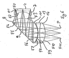
- Fig. 1 is shown in a schematic view from above of a user wearing the HMD device 1 according to the invention on the head.
- the HMD device has a spectacle-like frame 2 which rests on the nose of the user as well as on both ears (not shown).
- an imaging device 3 is attached to the frame 2.
- the image generating device 3 comprises, as shown in Fig. 1 for the left eye A1, a picture element 4, which here is a self-luminous microdisplay, and an imaging optics 5, with which the image generated by the picture element 4 is imaged so that the user can perceive it with his left eye A1.
- the exit pupil P of the imaging optics 5 lies in the plane of the pupil of the eye A1.
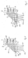
- Fig. 2 an embodiment of the image forming device 3 is shown in more detail.
- the picture element 4 is followed by a first optical group 6, which has a first lens 7 with negative refractive power and a second lens 8 with positive refractive power, a 90 ° deflecting prism 9 and a second optical group 10, which comprises a lens 11.
- the side of the first and second lenses 7 and 8 facing the picture element 4 is designed as an aspheric surface
- the side of the third lens 11 of the second optical group facing the exit pupil P is likewise designed as an aspheric surface.
- This aspheric surface is further configured as a diffractive surface, wherein the diffractive surface has a kinoform profile.
- the diffractive surface comprises concentric rings with the lens vertex of the exit pupil facing surface of the third lens as the center.
- Each ring has an inner and an outer radius.
- the inner radius of the first ring is zero.
- the outer radius of the mth ring is the inner radius of the m + 1th ring.
- the width of the rings becomes continuously smaller from the center to the edge of the lens.
- the groove depth at the inner radius is zero, at the outer radius it is d. In the transition from the mth ring to the m + 1th ring is thus a step of height d available.
- n 0 is the refractive index of the material for ⁇ 0 .
- the exact optical structure of the imaging optics 5 can be found in the following Tables 1 to 4, wherein Table 1 describes the lenses and the deflection prism, in Table 2, the aspherical surfaces and in Table 3, the diffractive surface are specified and Table 4, the materials used (see column “material” of Table 1).
- n d denotes the refractive index for 587.56 nm
- ⁇ d is the corresponding Abbe number
- ⁇ 1 is the density
- the second and third lenses 8, 11 are cemented onto the deflection prism 9. This has the advantage that the adjustment effort in the production of the imaging optics 5 can be reduced.
- the imaging optics shown thus has only (exactly) three lenses and thereby ensures an excellent imaging quality at an exit pupil with a diameter of 10 mm and a distance of the exit pupil from the last lens vertex of the third lens 11 of about 15 mm.
- the first optics group is used to correct astigmatism and distortion as well as to correct the lateral chromatic aberration.
- the second optical group in particular the aspherically diffractive surface F7 of the third lens 11, serves to correct the longitudinal chromatic aberration and the aperture error.
- the optics groups are designed so that, if the focal length of the imaging optics 5 is f, the focal length of the first lens 7 is f 1 and the focal length of the second lens is f 2 , the following relations hold: -1.2 f ⁇ f 1 ⁇ -0.3 f and 0.6 f ⁇ f 2 ⁇ 1.5 f.
- the second optical group has a positive focal length, wherein, when the focal length of the second optical group is denoted by f 3 , the following relationship applies: 0.6 f ⁇ f 3 ⁇ 1.7 f.
- L 2 the length of the imaging optics from the pixel 4 to the exit pupil P (along the optical axis)
- L 1 the length of the picture element 4 to the apex of the deflection element 9 with L 1
- L 2 the length from the apex of the deflection element 9 to the exit pupil P
- FIG. 3 a further embodiment of the imaging optics 5 is shown, wherein this embodiment differs from the embodiment shown in Fig. 2 in that the second lens 8 and the third lens 11 are formed the same.
- the number of different lenses can be reduced, resulting in cost savings in manufacturing are feasible.
- the exact structure of the imaging optics 5 can be found in the following Tables 5 to 7, which are constructed in the same manner as Tables 1 to 3.
- a further embodiment of the imaging optics 5 is shown, in turn, the second. Lens 8 and the third lens 11 are the same.
- the two lenses 8 and 11 are displaced in the axial direction only to each other and not mirrored to each other, as in the Embodiment of Fig. 3 is the case.
- the diffractive surface is formed on the aspherical side of the second and third lenses 8 and 11.
- FIG. 5 shows a further embodiment of the imaging optics 5, wherein in this case, in contrast to the previously described embodiments, the diffractive surface is formed on one side of a plane-parallel plate 12.
- the plane-parallel plate 12 is arranged between the exit pupil P and the third lens 11 of the second optical group 10 and the diffractive surface is provided on the side facing away from the exit pupil P.
- the second and third lenses are in turn cemented to the deflection prism 9.
- Tables 11 to 13 The exact structure of the imaging optics of Fig. 5 can be seen in the following Tables 11 to 13.
- FIG. 6 shows a further embodiment of the imaging optics according to the invention, this embodiment differing from the embodiments described so far in that no diffractive surface is provided in the second optical group 10, but an achromatizing adhesive group consisting of two lenses 13 and 14.
- FIG this Kittus the color longitudinal error is corrected.
Landscapes
- Physics & Mathematics (AREA)
- General Physics & Mathematics (AREA)
- Optics & Photonics (AREA)
- Lenses (AREA)
- Transforming Electric Information Into Light Information (AREA)
Claims (10)
- Dispositif Head Mounted Display (dispositif HMD) comprenant un élément d'image (4) pour générer une image et une optique de reproduction (5), qui reproduit l'image de telle sorte qu'elle peut être perçue par un utilisateur portant le dispositif HMD, l'optique de reproduction (5) comprenant un premier groupe optique (6) avec une première lentille (7), qui présente un pouvoir réfringent négatif, et une seconde lentille (8), qui présente un pouvoir réfringent positif, un élément de déviation (9) placé en aval du premier groupe optique (6) et un second groupe optique (10) suivant l'élément de déviation (9) avec une troisième lentille (11), caractérisé en ce que, pour la correction de l'astigmatisme et de la distorsion d'image, au moins une surface (F1, F2, F3, F4) des surfaces de la première et de la seconde lentilles (7, 8) est conçue de façon asphérique et, pour la correction de l'erreur d'ouverture, au moins une surface (F6, F7) de la troisième lentille (11) est conçue asphérique.
- Dispositif HMD selon la revendication 1 caractérisé en ce que, pour la correction de la courbure du champ visuel, la première lentille (7) est plus près d'un plan d'image, dans laquelle l'image est générée que la seconde lentille (8) et plus près du plan d'image que de l'élément de déviation (9).
- Dispositif HMD selon l'une quelconque des revendications précédentes, caractérisé en ce que, pour la correction de l'aberration chromatique latérale, le matériau de la première lentille (7) présente une dispersion plus grande que le matériau de la seconde lentille (8).
- Dispositif HDM selon l'une quelconque des revendications précédentes, caractérisé en ce que, pour la correction de l'aberration chromatique latérale, le second groupe optique (10) présente une surface diffractive et/ou une lentille achromatique.
- Dispositif HMD selon la revendication 4, caractérisé en ce que la surface diffractive est réalisée sur la surface asphérique de la troisième lentille (11).
- Dispositif HMD selon la revendication 4, caractérisé en ce que la surface diffractive est réalisée comme surface plane.
- Dispositif HMD selon l'une quelconque des revendications précédentes, caractérisé en ce que, pour la correction de l'astigmatisme et de la distorsion d'image, une surface de la première lentille (7) et une surface de la seconde lentille (8) sont conçues asphériques.
- Dispositif HMD selon l'une quelconque des revendications précédentes, caractérisé en ce que la seconde lentille (8) et la troisième lentille (11) sont conçues identiques.
- Dispositif HMD selon l'une quelconque des revendications précédentes, caractérisé en ce que l'élément de déviation (9) entraîne une convolution de la trajectoire de faisceau au moyen une unique réflection de 70° à 110°, de préférence 90°.
- Dispositif HMD selon l'une quelconque des revendications précédentes, caractérisé en ce que toutes les surfaces optiques des deux groupes optiques (6, 10) sont à symétrie de révolution et sont centrés par rapport à l'axe optique de l'optique de reproduction.
Priority Applications (5)
| Application Number | Priority Date | Filing Date | Title |
|---|---|---|---|
| EP03019980A EP1513000B8 (fr) | 2003-09-03 | 2003-09-03 | Viseur porté sur la tête avec système optique de reproduction comprenant une surface asphérique |
| AT03019980T ATE347120T1 (de) | 2003-09-03 | 2003-09-03 | Hmd-vorrichtung (head mounted display) mit einer eine asphärische fläche aufweisenden abbildungsoptik |
| DE50305854T DE50305854D1 (de) | 2003-09-03 | 2003-09-03 | HMD-Vorrichtung (Head Mounted Display) mit einer eine asphärische Fläche aufweisenden Abbildungsoptik |
| JP2004251400A JP2005099788A (ja) | 2003-09-03 | 2004-08-31 | 非球面を含む画像形成光学系を備えるhmdデバイス |
| US10/934,797 US6903875B2 (en) | 2003-09-03 | 2004-09-03 | HMD device with imaging optics comprising an aspheric surface |
Applications Claiming Priority (1)
| Application Number | Priority Date | Filing Date | Title |
|---|---|---|---|
| EP03019980A EP1513000B8 (fr) | 2003-09-03 | 2003-09-03 | Viseur porté sur la tête avec système optique de reproduction comprenant une surface asphérique |
Publications (3)
| Publication Number | Publication Date |
|---|---|
| EP1513000A1 EP1513000A1 (fr) | 2005-03-09 |
| EP1513000B1 true EP1513000B1 (fr) | 2006-11-29 |
| EP1513000B8 EP1513000B8 (fr) | 2007-02-14 |
Family
ID=34130117
Family Applications (1)
| Application Number | Title | Priority Date | Filing Date |
|---|---|---|---|
| EP03019980A Expired - Lifetime EP1513000B8 (fr) | 2003-09-03 | 2003-09-03 | Viseur porté sur la tête avec système optique de reproduction comprenant une surface asphérique |
Country Status (5)
| Country | Link |
|---|---|
| US (1) | US6903875B2 (fr) |
| EP (1) | EP1513000B8 (fr) |
| JP (1) | JP2005099788A (fr) |
| AT (1) | ATE347120T1 (fr) |
| DE (1) | DE50305854D1 (fr) |
Families Citing this family (53)
| Publication number | Priority date | Publication date | Assignee | Title |
|---|---|---|---|---|
| FR2868551B1 (fr) * | 2004-04-02 | 2006-08-04 | Essilor Int | Conduit optique destine a la realisation d'un agencement d'affichage electronique |
| US7545571B2 (en) * | 2004-09-08 | 2009-06-09 | Concurrent Technologies Corporation | Wearable display system |
| DE102005054183A1 (de) * | 2005-11-14 | 2007-05-16 | Zeiss Carl Ag | HMD-Vorrichtung |
| US7586686B1 (en) | 2006-04-14 | 2009-09-08 | Oasys Technology Llc | Eyepiece for head mounted display system and method of fabrication |
| FR2902896B1 (fr) * | 2006-06-21 | 2008-12-12 | Essilor Int | Conduit optique destine a la realisation d'un agencement d'affichage electronique |
| FR2906374B1 (fr) * | 2006-09-21 | 2008-12-05 | Essilor Int | Agencement d'affichage electronique |
| KR100844168B1 (ko) * | 2006-10-23 | 2008-07-04 | 방주광학 주식회사 | 헤드마운트 디스플레이용 광학 시스템 |
| DE202007019170U1 (de) * | 2007-03-29 | 2010-11-04 | Carl Zeiss Ag | HMD-Vorrichtung |
| DE102007015278A1 (de) | 2007-03-29 | 2008-10-02 | Carl Zeiss Ag | Optisches Okularsystem |
| US8094377B2 (en) * | 2009-05-13 | 2012-01-10 | Nvis, Inc. | Head-mounted optical apparatus using an OLED display |
| US9759917B2 (en) | 2010-02-28 | 2017-09-12 | Microsoft Technology Licensing, Llc | AR glasses with event and sensor triggered AR eyepiece interface to external devices |
| US10180572B2 (en) | 2010-02-28 | 2019-01-15 | Microsoft Technology Licensing, Llc | AR glasses with event and user action control of external applications |
| US9182596B2 (en) * | 2010-02-28 | 2015-11-10 | Microsoft Technology Licensing, Llc | See-through near-eye display glasses with the optical assembly including absorptive polarizers or anti-reflective coatings to reduce stray light |
| US9091851B2 (en) | 2010-02-28 | 2015-07-28 | Microsoft Technology Licensing, Llc | Light control in head mounted displays |
| US9285589B2 (en) | 2010-02-28 | 2016-03-15 | Microsoft Technology Licensing, Llc | AR glasses with event and sensor triggered control of AR eyepiece applications |
| US9223134B2 (en) * | 2010-02-28 | 2015-12-29 | Microsoft Technology Licensing, Llc | Optical imperfections in a light transmissive illumination system for see-through near-eye display glasses |
| US9097890B2 (en) * | 2010-02-28 | 2015-08-04 | Microsoft Technology Licensing, Llc | Grating in a light transmissive illumination system for see-through near-eye display glasses |
| AU2011220382A1 (en) | 2010-02-28 | 2012-10-18 | Microsoft Corporation | Local advertising content on an interactive head-mounted eyepiece |
| US9341843B2 (en) | 2010-02-28 | 2016-05-17 | Microsoft Technology Licensing, Llc | See-through near-eye display glasses with a small scale image source |
| US9229227B2 (en) | 2010-02-28 | 2016-01-05 | Microsoft Technology Licensing, Llc | See-through near-eye display glasses with a light transmissive wedge shaped illumination system |
| US9366862B2 (en) | 2010-02-28 | 2016-06-14 | Microsoft Technology Licensing, Llc | System and method for delivering content to a group of see-through near eye display eyepieces |
| US20150309316A1 (en) | 2011-04-06 | 2015-10-29 | Microsoft Technology Licensing, Llc | Ar glasses with predictive control of external device based on event input |
| US9134534B2 (en) * | 2010-02-28 | 2015-09-15 | Microsoft Technology Licensing, Llc | See-through near-eye display glasses including a modular image source |
| US9129295B2 (en) | 2010-02-28 | 2015-09-08 | Microsoft Technology Licensing, Llc | See-through near-eye display glasses with a fast response photochromic film system for quick transition from dark to clear |
| US20120235887A1 (en) * | 2010-02-28 | 2012-09-20 | Osterhout Group, Inc. | See-through near-eye display glasses including a partially reflective, partially transmitting optical element and an optically flat film |
| US20120249797A1 (en) | 2010-02-28 | 2012-10-04 | Osterhout Group, Inc. | Head-worn adaptive display |
| US9097891B2 (en) * | 2010-02-28 | 2015-08-04 | Microsoft Technology Licensing, Llc | See-through near-eye display glasses including an auto-brightness control for the display brightness based on the brightness in the environment |
| US9128281B2 (en) | 2010-09-14 | 2015-09-08 | Microsoft Technology Licensing, Llc | Eyepiece with uniformly illuminated reflective display |
| USD673995S1 (en) | 2012-02-23 | 2013-01-08 | 3-D Etc., LLC | Blinder for head mounted display |
| TWI588560B (zh) | 2012-04-05 | 2017-06-21 | 布萊恩荷登視覺協會 | 用於屈光不正之鏡片、裝置、方法及系統 |
| US9201250B2 (en) | 2012-10-17 | 2015-12-01 | Brien Holden Vision Institute | Lenses, devices, methods and systems for refractive error |
| HK1212194A1 (en) | 2012-10-17 | 2016-06-10 | Brien Holden Vision Institute | Lenses, devices, methods and systems for refractive error |
| CN104583842B (zh) * | 2013-04-11 | 2019-02-15 | 索尼公司 | 图像显示装置和显示设备 |
| JP6358248B2 (ja) | 2013-04-11 | 2018-07-18 | ソニー株式会社 | 表示装置 |
| DE102013207257B4 (de) * | 2013-04-22 | 2021-03-04 | Carl Zeiss Jena Gmbh | Anzeigevorrichtung |
| US9341850B1 (en) * | 2013-04-30 | 2016-05-17 | Google Inc. | Diffractive see-through display with hybrid-optical aberration compensation |
| US9952435B2 (en) | 2013-07-16 | 2018-04-24 | Sony Corporation | Display apparatus having curved image forming apparatus |
| US10534172B2 (en) | 2013-07-16 | 2020-01-14 | Sony Corporation | Display apparatus |
| EP2887124A1 (fr) * | 2013-12-20 | 2015-06-24 | Thomson Licensing | Dispositif d'affichage à verre transparent optique et unité optique correspondante |
| TWI531817B (zh) * | 2014-01-16 | 2016-05-01 | 中強光電股份有限公司 | 虛像顯示模組與光學鏡頭 |
| TWI519818B (zh) * | 2014-05-28 | 2016-02-01 | 中強光電股份有限公司 | 光學鏡頭與虛像顯示模組 |
| US10746994B2 (en) | 2014-08-07 | 2020-08-18 | Microsoft Technology Licensing, Llc | Spherical mirror having a decoupled aspheric |
| CN105917267B (zh) | 2015-09-13 | 2018-06-12 | 深圳市柔宇科技有限公司 | 光学模组、光学装置及穿戴式显示装置 |
| CN105137590B (zh) * | 2015-09-28 | 2017-09-12 | 深圳纳德光学有限公司 | 大视场角目镜光学系统 |
| WO2017181359A1 (fr) * | 2016-04-20 | 2017-10-26 | 深圳纳德光学有限公司 | Système optique d'oculaire pour afficheur proche de l'œil, et dispositif visiocasque |
| CN106338830A (zh) * | 2016-08-31 | 2017-01-18 | 深圳超多维科技有限公司 | 图像显示装置及头戴式显示设备 |
| CN106338831A (zh) * | 2016-08-31 | 2017-01-18 | 深圳超多维科技有限公司 | 图像显示装置及头戴式显示设备 |
| US11402635B1 (en) * | 2018-05-24 | 2022-08-02 | Facebook Technologies, Llc | Systems and methods for measuring visual refractive error |
| CN111948823B (zh) * | 2020-08-21 | 2024-01-23 | 香港理工大学 | 一种可抑制近视加深的虚拟现实设备及其光路结构 |
| CN111929899A (zh) * | 2020-08-21 | 2020-11-13 | 香港理工大学 | 一种增强现实头戴显示设备 |
| JP2022125938A (ja) * | 2021-02-17 | 2022-08-29 | 株式会社日立エルジーデータストレージ | 映像投射装置 |
| CN113341557B (zh) * | 2021-08-02 | 2022-08-02 | 深圳纳德光学有限公司 | 一种反射式目镜光学系统及头戴近眼显示装置 |
| CN119126366B (zh) * | 2023-06-12 | 2026-01-27 | 浙江舜宇光学有限公司 | 一种目镜成像系统 |
Family Cites Families (11)
| Publication number | Priority date | Publication date | Assignee | Title |
|---|---|---|---|---|
| US5151823A (en) | 1991-09-23 | 1992-09-29 | Hughes Aircraft Company | Biocular eyepiece optical system employing refractive and diffractive optical elements |
| US5768025A (en) | 1995-08-21 | 1998-06-16 | Olympus Optical Co., Ltd. | Optical system and image display apparatus |
| JP3636240B2 (ja) | 1996-03-25 | 2005-04-06 | オリンパス株式会社 | 光学系 |
| US5959780A (en) | 1996-04-15 | 1999-09-28 | Olympus Optical Co., Ltd. | Head-mounted display apparatus comprising a rotationally asymmetric surface |
| US5771124A (en) * | 1996-07-02 | 1998-06-23 | Siliscape | Compact display system with two stage magnification and immersed beam splitter |
| US6204974B1 (en) | 1996-10-08 | 2001-03-20 | The Microoptical Corporation | Compact image display system for eyeglasses or other head-borne frames |
| US6023372A (en) | 1997-10-30 | 2000-02-08 | The Microoptical Corporation | Light weight, compact remountable electronic display device for eyeglasses or other head-borne eyewear frames |
| US5886822A (en) | 1996-10-08 | 1999-03-23 | The Microoptical Corporation | Image combining system for eyeglasses and face masks |
| HUP9602917A3 (en) * | 1996-10-22 | 2001-10-29 | Nagykalnai Endre | Display installed to the user`s head |
| JP2000187177A (ja) | 1998-12-22 | 2000-07-04 | Olympus Optical Co Ltd | 画像表示装置 |
| US6349004B1 (en) * | 1999-07-16 | 2002-02-19 | Optics 1, Inc. | Head mounted display viewing optics with improved optical performance |
-
2003
- 2003-09-03 EP EP03019980A patent/EP1513000B8/fr not_active Expired - Lifetime
- 2003-09-03 DE DE50305854T patent/DE50305854D1/de not_active Expired - Lifetime
- 2003-09-03 AT AT03019980T patent/ATE347120T1/de not_active IP Right Cessation
-
2004
- 2004-08-31 JP JP2004251400A patent/JP2005099788A/ja active Pending
- 2004-09-03 US US10/934,797 patent/US6903875B2/en not_active Expired - Lifetime
Also Published As
| Publication number | Publication date |
|---|---|
| US6903875B2 (en) | 2005-06-07 |
| ATE347120T1 (de) | 2006-12-15 |
| DE50305854D1 (de) | 2007-01-11 |
| EP1513000A1 (fr) | 2005-03-09 |
| US20050046954A1 (en) | 2005-03-03 |
| JP2005099788A (ja) | 2005-04-14 |
| EP1513000B8 (fr) | 2007-02-14 |
Similar Documents
| Publication | Publication Date | Title |
|---|---|---|
| EP1513000B1 (fr) | Viseur porté sur la tête avec système optique de reproduction comprenant une surface asphérique | |
| EP3072005B1 (fr) | Optique d'imagerie et dispositif d'affichage présentant une telle optique d'imagerie | |
| EP3353588B1 (fr) | Dispositif d'affichage pourvu d'une optique de reproduction | |
| EP2601553B1 (fr) | Dispositif d'affichage présentant un dispositif de retenue pouvant être placé sur la tête d'un utilisateur | |
| EP3072006B1 (fr) | Optique de reproduction et dispositif d'affichage muni de ladite optique d'imagerie | |
| DE102013214700B4 (de) | Brillenglas sowie Anzeigevorrichtung mit einem solchen Brillenglas | |
| DE102013219623B4 (de) | Brillenglas für eine auf den Kopf eines Benutzers aufsetzbare und ein Bild erzeugende Anzeigevorrichtung sowie Anzeigevorrichtung mit einem solchen Brillenglas | |
| EP3391129B1 (fr) | Élément optique ophtalmique et procédé de pose d'un element optique ophtalmique | |
| DE102014207499A1 (de) | Brillenglas für eine auf den Kopf eines Benutzers aufsetzbare und ein Bild erzeugende Anzeigevorrichtung | |
| EP2130083A1 (fr) | Système oculaire | |
| EP3458900A1 (fr) | Verre de lunettes pour système optique de reproduction et lunettes de données | |
| DE102014119550A1 (de) | Abbildungsoptik zum Erzeugen eines virtuellen Bildes und Datenbrille | |
| DE102014107938B4 (de) | Anzeigevorrichtung | |
| DE102007046505B4 (de) | Anzeigevorrichtung und Stereo-Anzeigemodul | |
| DE69024771T2 (de) | Vorrichtung zum Anzeigen eines virtuellen Bildes mit zwei Spiegeln für das Armaturenbrett eines Fahrzeugs | |
| DE102017101352A1 (de) | Brillenglas für eine auf den Kopf eines Benutzers aufsetzbare und ein Bild erzeugende Anzeigevorrichtung | |
| DE102007036974B4 (de) | HMD-Vorrichtung | |
| EP1787154B1 (fr) | Objectif | |
| DE102007046711B4 (de) | Anzeigevorrichtung | |
| DE2413472A1 (de) | Retrofokus-weitwinkel-aufnahmeobjektiv | |
| DE102004020818A1 (de) | Anzeigevorrichtung | |
| EP4377728B1 (fr) | Unité de projection et dispositif de projection comportant une unité de projection | |
| DE102024104823A1 (de) | Brillenglas für eine auf den Kopf eines Benutzers aufsetzbare und ein Bild erzeugende Anzeigevorrichtung sowie Anzeigevorrichtung mit einem solchen Brillenglas | |
| DE202005021014U1 (de) | HMD-Vorrichtung | |
| DE102025120170A1 (de) | Optisches anzeigesystem und anzeigevorrichtung |
Legal Events
| Date | Code | Title | Description |
|---|---|---|---|
| PUAI | Public reference made under article 153(3) epc to a published international application that has entered the european phase |
Free format text: ORIGINAL CODE: 0009012 |
|
| AK | Designated contracting states |
Kind code of ref document: A1 Designated state(s): AT BE BG CH CY CZ DE DK EE ES FI FR GB GR HU IE IT LI LU MC NL PT RO SE SI SK TR |
|
| AX | Request for extension of the european patent |
Extension state: AL LT LV MK |
|
| 17P | Request for examination filed |
Effective date: 20050907 |
|
| AKX | Designation fees paid |
Designated state(s): AT BE BG CH CY CZ DE DK EE ES FI FR GB GR HU IE IT LI LU MC NL PT RO SE SI SK TR |
|
| GRAP | Despatch of communication of intention to grant a patent |
Free format text: ORIGINAL CODE: EPIDOSNIGR1 |
|
| GRAS | Grant fee paid |
Free format text: ORIGINAL CODE: EPIDOSNIGR3 |
|
| GRAA | (expected) grant |
Free format text: ORIGINAL CODE: 0009210 |
|
| AK | Designated contracting states |
Kind code of ref document: B1 Designated state(s): AT BE BG CH CY CZ DE DK EE ES FI FR GB GR HU IE IT LI LU MC NL PT RO SE SI SK TR |
|
| PG25 | Lapsed in a contracting state [announced via postgrant information from national office to epo] |
Ref country code: IT Free format text: LAPSE BECAUSE OF FAILURE TO SUBMIT A TRANSLATION OF THE DESCRIPTION OR TO PAY THE FEE WITHIN THE PRESCRIBED TIME-LIMIT;WARNING: LAPSES OF ITALIAN PATENTS WITH EFFECTIVE DATE BEFORE 2007 MAY HAVE OCCURRED AT ANY TIME BEFORE 2007. THE CORRECT EFFECTIVE DATE MAY BE DIFFERENT FROM THE ONE RECORDED. Effective date: 20061129 Ref country code: SI Free format text: LAPSE BECAUSE OF FAILURE TO SUBMIT A TRANSLATION OF THE DESCRIPTION OR TO PAY THE FEE WITHIN THE PRESCRIBED TIME-LIMIT Effective date: 20061129 Ref country code: IE Free format text: LAPSE BECAUSE OF FAILURE TO SUBMIT A TRANSLATION OF THE DESCRIPTION OR TO PAY THE FEE WITHIN THE PRESCRIBED TIME-LIMIT Effective date: 20061129 Ref country code: CZ Free format text: LAPSE BECAUSE OF FAILURE TO SUBMIT A TRANSLATION OF THE DESCRIPTION OR TO PAY THE FEE WITHIN THE PRESCRIBED TIME-LIMIT Effective date: 20061129 Ref country code: NL Free format text: LAPSE BECAUSE OF FAILURE TO SUBMIT A TRANSLATION OF THE DESCRIPTION OR TO PAY THE FEE WITHIN THE PRESCRIBED TIME-LIMIT Effective date: 20061129 Ref country code: RO Free format text: LAPSE BECAUSE OF FAILURE TO SUBMIT A TRANSLATION OF THE DESCRIPTION OR TO PAY THE FEE WITHIN THE PRESCRIBED TIME-LIMIT Effective date: 20061129 Ref country code: FI Free format text: LAPSE BECAUSE OF FAILURE TO SUBMIT A TRANSLATION OF THE DESCRIPTION OR TO PAY THE FEE WITHIN THE PRESCRIBED TIME-LIMIT Effective date: 20061129 Ref country code: SK Free format text: LAPSE BECAUSE OF FAILURE TO SUBMIT A TRANSLATION OF THE DESCRIPTION OR TO PAY THE FEE WITHIN THE PRESCRIBED TIME-LIMIT Effective date: 20061129 |
|
| REG | Reference to a national code |
Ref country code: GB Ref legal event code: FG4D Free format text: NOT ENGLISH |
|
| REG | Reference to a national code |
Ref country code: CH Ref legal event code: EP |
|
| RAP2 | Party data changed (patent owner data changed or rights of a patent transferred) |
Owner name: CARL ZEISS Owner name: CARL ZEISS STIFTUNG Owner name: CARL ZEISS AG |
|
| REG | Reference to a national code |
Ref country code: IE Ref legal event code: FG4D Free format text: LANGUAGE OF EP DOCUMENT: GERMAN |
|
| REF | Corresponds to: |
Ref document number: 50305854 Country of ref document: DE Date of ref document: 20070111 Kind code of ref document: P |
|
| PG25 | Lapsed in a contracting state [announced via postgrant information from national office to epo] |
Ref country code: SE Free format text: LAPSE BECAUSE OF FAILURE TO SUBMIT A TRANSLATION OF THE DESCRIPTION OR TO PAY THE FEE WITHIN THE PRESCRIBED TIME-LIMIT Effective date: 20070228 Ref country code: DK Free format text: LAPSE BECAUSE OF FAILURE TO SUBMIT A TRANSLATION OF THE DESCRIPTION OR TO PAY THE FEE WITHIN THE PRESCRIBED TIME-LIMIT Effective date: 20070228 Ref country code: BG Free format text: LAPSE BECAUSE OF FAILURE TO SUBMIT A TRANSLATION OF THE DESCRIPTION OR TO PAY THE FEE WITHIN THE PRESCRIBED TIME-LIMIT Effective date: 20070228 |
|
| NLT2 | Nl: modifications (of names), taken from the european patent patent bulletin |
Owner name: CARL ZEISS Effective date: 20070110 |
|
| PG25 | Lapsed in a contracting state [announced via postgrant information from national office to epo] |
Ref country code: ES Free format text: LAPSE BECAUSE OF FAILURE TO SUBMIT A TRANSLATION OF THE DESCRIPTION OR TO PAY THE FEE WITHIN THE PRESCRIBED TIME-LIMIT Effective date: 20070312 |
|
| PG25 | Lapsed in a contracting state [announced via postgrant information from national office to epo] |
Ref country code: PT Free format text: LAPSE BECAUSE OF FAILURE TO SUBMIT A TRANSLATION OF THE DESCRIPTION OR TO PAY THE FEE WITHIN THE PRESCRIBED TIME-LIMIT Effective date: 20070430 |
|
| NLV1 | Nl: lapsed or annulled due to failure to fulfill the requirements of art. 29p and 29m of the patents act | ||
| GBV | Gb: ep patent (uk) treated as always having been void in accordance with gb section 77(7)/1977 [no translation filed] |
Effective date: 20061129 |
|
| REG | Reference to a national code |
Ref country code: IE Ref legal event code: FD4D |
|
| EN | Fr: translation not filed | ||
| PLBE | No opposition filed within time limit |
Free format text: ORIGINAL CODE: 0009261 |
|
| STAA | Information on the status of an ep patent application or granted ep patent |
Free format text: STATUS: NO OPPOSITION FILED WITHIN TIME LIMIT |
|
| 26N | No opposition filed |
Effective date: 20070830 |
|
| PG25 | Lapsed in a contracting state [announced via postgrant information from national office to epo] |
Ref country code: GB Free format text: LAPSE BECAUSE OF FAILURE TO SUBMIT A TRANSLATION OF THE DESCRIPTION OR TO PAY THE FEE WITHIN THE PRESCRIBED TIME-LIMIT Effective date: 20061129 |
|
| BERE | Be: lapsed |
Owner name: CARL ZEISS Effective date: 20070930 Owner name: CARL ZEISS STIFTUNG Effective date: 20070930 |
|
| PG25 | Lapsed in a contracting state [announced via postgrant information from national office to epo] |
Ref country code: GR Free format text: LAPSE BECAUSE OF FAILURE TO SUBMIT A TRANSLATION OF THE DESCRIPTION OR TO PAY THE FEE WITHIN THE PRESCRIBED TIME-LIMIT Effective date: 20070301 Ref country code: FR Free format text: LAPSE BECAUSE OF FAILURE TO SUBMIT A TRANSLATION OF THE DESCRIPTION OR TO PAY THE FEE WITHIN THE PRESCRIBED TIME-LIMIT Effective date: 20070720 Ref country code: MC Free format text: LAPSE BECAUSE OF NON-PAYMENT OF DUE FEES Effective date: 20070930 |
|
| REG | Reference to a national code |
Ref country code: CH Ref legal event code: PL |
|
| PG25 | Lapsed in a contracting state [announced via postgrant information from national office to epo] |
Ref country code: LI Free format text: LAPSE BECAUSE OF NON-PAYMENT OF DUE FEES Effective date: 20070930 Ref country code: CH Free format text: LAPSE BECAUSE OF NON-PAYMENT OF DUE FEES Effective date: 20070930 |
|
| PG25 | Lapsed in a contracting state [announced via postgrant information from national office to epo] |
Ref country code: BE Free format text: LAPSE BECAUSE OF NON-PAYMENT OF DUE FEES Effective date: 20070930 |
|
| PG25 | Lapsed in a contracting state [announced via postgrant information from national office to epo] |
Ref country code: FR Free format text: LAPSE BECAUSE OF FAILURE TO SUBMIT A TRANSLATION OF THE DESCRIPTION OR TO PAY THE FEE WITHIN THE PRESCRIBED TIME-LIMIT Effective date: 20061129 Ref country code: AT Free format text: LAPSE BECAUSE OF NON-PAYMENT OF DUE FEES Effective date: 20070903 |
|
| PG25 | Lapsed in a contracting state [announced via postgrant information from national office to epo] |
Ref country code: EE Free format text: LAPSE BECAUSE OF FAILURE TO SUBMIT A TRANSLATION OF THE DESCRIPTION OR TO PAY THE FEE WITHIN THE PRESCRIBED TIME-LIMIT Effective date: 20061129 |
|
| PG25 | Lapsed in a contracting state [announced via postgrant information from national office to epo] |
Ref country code: LU Free format text: LAPSE BECAUSE OF NON-PAYMENT OF DUE FEES Effective date: 20070903 Ref country code: CY Free format text: LAPSE BECAUSE OF FAILURE TO SUBMIT A TRANSLATION OF THE DESCRIPTION OR TO PAY THE FEE WITHIN THE PRESCRIBED TIME-LIMIT Effective date: 20061129 |
|
| PG25 | Lapsed in a contracting state [announced via postgrant information from national office to epo] |
Ref country code: TR Free format text: LAPSE BECAUSE OF FAILURE TO SUBMIT A TRANSLATION OF THE DESCRIPTION OR TO PAY THE FEE WITHIN THE PRESCRIBED TIME-LIMIT Effective date: 20061129 Ref country code: HU Free format text: LAPSE BECAUSE OF FAILURE TO SUBMIT A TRANSLATION OF THE DESCRIPTION OR TO PAY THE FEE WITHIN THE PRESCRIBED TIME-LIMIT Effective date: 20070530 |
|
| PGFP | Annual fee paid to national office [announced via postgrant information from national office to epo] |
Ref country code: DE Payment date: 20210920 Year of fee payment: 19 |
|
| REG | Reference to a national code |
Ref country code: DE Ref legal event code: R119 Ref document number: 50305854 Country of ref document: DE |
|
| PG25 | Lapsed in a contracting state [announced via postgrant information from national office to epo] |
Ref country code: DE Free format text: LAPSE BECAUSE OF NON-PAYMENT OF DUE FEES Effective date: 20230401 |