EP1513000B1 - HMD-Vorrichtung (Head Mounted Display) mit einer eine asphärische Fläche aufweisenden Abbildungsoptik - Google Patents
HMD-Vorrichtung (Head Mounted Display) mit einer eine asphärische Fläche aufweisenden Abbildungsoptik Download PDFInfo
- Publication number
- EP1513000B1 EP1513000B1 EP03019980A EP03019980A EP1513000B1 EP 1513000 B1 EP1513000 B1 EP 1513000B1 EP 03019980 A EP03019980 A EP 03019980A EP 03019980 A EP03019980 A EP 03019980A EP 1513000 B1 EP1513000 B1 EP 1513000B1
- Authority
- EP
- European Patent Office
- Prior art keywords
- lens
- hmd device
- correction
- optical
- optical group
- Prior art date
- Legal status (The legal status is an assumption and is not a legal conclusion. Google has not performed a legal analysis and makes no representation as to the accuracy of the status listed.)
- Expired - Lifetime
Links
- 238000003384 imaging method Methods 0.000 title claims description 41
- 230000003287 optical effect Effects 0.000 claims abstract description 55
- 230000004075 alteration Effects 0.000 claims abstract description 12
- 201000009310 astigmatism Diseases 0.000 claims abstract description 9
- 239000000463 material Substances 0.000 claims description 14
- 239000006185 dispersion Substances 0.000 claims description 2
- 210000001747 pupil Anatomy 0.000 abstract description 18
- 229920003229 poly(methyl methacrylate) Polymers 0.000 description 23
- 239000004926 polymethyl methacrylate Substances 0.000 description 23
- 238000004519 manufacturing process Methods 0.000 description 4
- 210000003128 head Anatomy 0.000 description 2
- 101100129500 Caenorhabditis elegans max-2 gene Proteins 0.000 description 1
- 241000700608 Sagitta Species 0.000 description 1
- 241000897276 Termes Species 0.000 description 1
- 239000000853 adhesive Substances 0.000 description 1
- 230000001070 adhesive effect Effects 0.000 description 1
- 230000003190 augmentative effect Effects 0.000 description 1
- 210000005069 ears Anatomy 0.000 description 1
- 230000004424 eye movement Effects 0.000 description 1
- 238000013507 mapping Methods 0.000 description 1
- 239000004033 plastic Substances 0.000 description 1
- 229920003023 plastic Polymers 0.000 description 1
- 230000007704 transition Effects 0.000 description 1
Images


Classifications
-
- G—PHYSICS
- G02—OPTICS
- G02B—OPTICAL ELEMENTS, SYSTEMS OR APPARATUS
- G02B3/00—Simple or compound lenses
- G02B3/02—Simple or compound lenses with non-spherical faces
- G02B3/04—Simple or compound lenses with non-spherical faces with continuous faces that are rotationally symmetrical but deviate from a true sphere, e.g. so called "aspheric" lenses
-
- G—PHYSICS
- G02—OPTICS
- G02B—OPTICAL ELEMENTS, SYSTEMS OR APPARATUS
- G02B27/00—Optical systems or apparatus not provided for by any of the groups G02B1/00 - G02B26/00, G02B30/00
- G02B27/0025—Optical systems or apparatus not provided for by any of the groups G02B1/00 - G02B26/00, G02B30/00 for optical correction, e.g. distorsion, aberration
-
- G—PHYSICS
- G02—OPTICS
- G02B—OPTICAL ELEMENTS, SYSTEMS OR APPARATUS
- G02B27/00—Optical systems or apparatus not provided for by any of the groups G02B1/00 - G02B26/00, G02B30/00
- G02B27/01—Head-up displays
- G02B27/017—Head mounted
- G02B27/0172—Head mounted characterised by optical features
-
- G—PHYSICS
- G02—OPTICS
- G02B—OPTICAL ELEMENTS, SYSTEMS OR APPARATUS
- G02B27/00—Optical systems or apparatus not provided for by any of the groups G02B1/00 - G02B26/00, G02B30/00
- G02B27/01—Head-up displays
- G02B27/0101—Head-up displays characterised by optical features
- G02B2027/011—Head-up displays characterised by optical features comprising device for correcting geometrical aberrations, distortion
-
- G—PHYSICS
- G02—OPTICS
- G02B—OPTICAL ELEMENTS, SYSTEMS OR APPARATUS
- G02B27/00—Optical systems or apparatus not provided for by any of the groups G02B1/00 - G02B26/00, G02B30/00
- G02B27/01—Head-up displays
- G02B27/0101—Head-up displays characterised by optical features
- G02B2027/0132—Head-up displays characterised by optical features comprising binocular systems
-
- G—PHYSICS
- G02—OPTICS
- G02B—OPTICAL ELEMENTS, SYSTEMS OR APPARATUS
- G02B27/00—Optical systems or apparatus not provided for by any of the groups G02B1/00 - G02B26/00, G02B30/00
- G02B27/01—Head-up displays
- G02B27/017—Head mounted
- G02B2027/0178—Eyeglass type
Definitions
- the invention relates to an HMD device (H ead m ounted d isplay - device) with an image element for generating an image and imaging optics, which images the image so that it is perceivable by an HMD device supporting the user, whereby the imaging optics a first optical group having a first lens having a negative refractive power, and a second lens having a positive refractive power, a deflecting element arranged downstream of the first optical group, and a second optical group having a third lens following the deflecting element.
- Such an HMD device is known from WO 98/18038. Difficulties exist in such a known HMD device is that the exit pupil of the imaging optics must be so that at this point the user carrying the HMD device can bring his eye, at the same time the diameter of the exit pupil must be so large that even at Eye movements of the user can perceive the entire picture. Thus, the diameter of the exit pupil should be at least 8mm and at the same time a field of the size of 25 ° should be made available, whereby over this field and over the exit pupil a good optical image quality should be realized. Such requirements can be met by the provision of additional lenses. However, an increase in the number of lenses is disadvantageously associated with a weight and size increase.
- the object is achieved with an HMD device of the type mentioned in that for correcting astigmatism and distortion at least one surface of the surfaces of the first and second lens is aspherical and formed to correct the aperture error at least one surface of the third lens aspherical ,
- the provision of an aspherical surface in the first optical group and an aspheric surface in the second optical group is advantageous in that by the first optical group, mainly the correction of astigmatism and distortion can be realized and the correction of the aperture error is mainly performed by the second optical group.
- the correction of the different aberrations is divided between the two optical groups, thereby advantageously an excellent correction and thus an excellent optical image quality for the viewer is achieved.
- the first lens is closer to an image plane in which the generated image lies than the second lens and is also closer to the image plane than to the deflection element.
- a very short distance of the first lens to the generated image can be realized, whereby an excellent correction of the field curvature is achieved.
- the material of the first lens can have a higher dispersion than the material of the second lens in order to correct the lateral chromatic aberration. Since the first optical group is arranged between the deflecting element and the image plane, the first optical group is relatively close to the image (compared to the second optical group), whereby excellent correction of the lateral chromatic aberration can be achieved.
- a particularly preferred embodiment of the HMD device according to the invention is that for correcting the longitudinal chromatic aberration, the second optical group has a diffräktive surface and / or an achromat. Since the second optical group is closer to the exit pupil of the imaging optics than the first optical group, a very good correction of the longitudinal chromatic aberration can be realized.
- the diffractive surface in the second optical group for correcting the longitudinal chromatic aberration leads to the advantage that no additional optical elements must be provided thereby.
- the diffractive surface can be formed on a surface of the third lens, in particular on the aspherical surface of the third lens.
- the diffractive surface it is also possible to form the diffractive surface as a plane surface, which is provided on a thin plane-parallel plate or, if a deflecting prism as deflection element is provided, on which the second optical group facing side of the Umlenkprismas is formed.
- the HMD device according to the invention can be further developed in that, for the correction of astigmatism and distortion, both an area of the first lens and an area of the second lens are aspherical.
- An advantageous development of the HMD device according to the invention is that the second and third lenses are identical. Thereby, the number of different optical elements is reduced, whereby the manufacturing cost can be reduced.
- the second and third lenses can be arranged so that they are only shifted from each other along the optical axis or are also arranged mirrored to each other.
- the deflection element can cause the beam path to be folded by means of a single reflection by 70 ° -110 °, preferably 90 °.
- a deflection prism can be used as a deflection. This leads to the advantage that, compared to a deflecting mirror as deflection element, the prism can be made smaller in order to provide the same optical path length (due to the refractive index of greater than 1 of the prism material). This leads to a more compact and lighter arrangement.
- deflecting mirror as deflecting leads to the advantage that such a deflecting mirror can be manufactured extremely inexpensively with the required accuracy, whereby the manufacturing cost of the HMD device according to the invention can be reduced.
- the HMD device according to the invention can be further developed in that all optical surfaces of the two optical groups are centered rotationally symmetrically and with respect to the optical axis of the imaging optics.
- This provides a compact imaging optic with excellent imaging properties.
- all the lenses of the two optical groups can be made of plastic, whereby the weight of the imaging optics can be kept very low.
- the second optical group preferably has positive refractive power. Thereby, the HMD device can be made compact.
- the HMD device is designed such that only the generated image is perceptible to the viewer.
- the HMD device can be designed for an augmented display, in which the viewer perceives the generated image in superimposition with the surroundings.
- the ambient light preferably passes through the deflection element and the second optical group (and not through the first optical group). It is also possible to arrange a third optical group in front of the deflection element, through which the ambient light passes before it passes through the deflection element and the second optical group.
- the imaging optics preferably generates a virtual image of the image generated by means of the image element, wherein in particular a mapping to infinity is possible.
- the exit pupil of the imaging optics is behind the second optics group (ie in air), so that the viewer can easily bring his eye to the place of the exit pupil with attached HMD device.
- the HMD device according to the invention may also contain a drive unit for driving the picture element on the basis of predetermined image data, the picture element being either a self-luminous picture element, such as e.g. an OLED (organic LED), or may be a non-self-luminous picture element which may be reflective or transmissive (e.g., LCD module, tilt mirror array).
- the image plane in which the image is formed may be given by the pixel itself or may be spaced from the pixel. In the latter case, an intermediate imaging optics may be arranged between the picture element and the image plane.
- the HMD device according to the invention can also have a suitable holding device or a suitable frame with which it can be placed on the head of the user. This frame may be similar to a spectacle frame.
- the HMD device can be designed for both eye and both eye imaging and the pixel can produce monochrome or multicolor images.
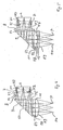
- Fig. 1 is shown in a schematic view from above of a user wearing the HMD device 1 according to the invention on the head.
- the HMD device has a spectacle-like frame 2 which rests on the nose of the user as well as on both ears (not shown).
- an imaging device 3 is attached to the frame 2.
- the image generating device 3 comprises, as shown in Fig. 1 for the left eye A1, a picture element 4, which here is a self-luminous microdisplay, and an imaging optics 5, with which the image generated by the picture element 4 is imaged so that the user can perceive it with his left eye A1.
- the exit pupil P of the imaging optics 5 lies in the plane of the pupil of the eye A1.
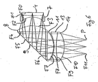
- Fig. 2 an embodiment of the image forming device 3 is shown in more detail.
- the picture element 4 is followed by a first optical group 6, which has a first lens 7 with negative refractive power and a second lens 8 with positive refractive power, a 90 ° deflecting prism 9 and a second optical group 10, which comprises a lens 11.
- the side of the first and second lenses 7 and 8 facing the picture element 4 is designed as an aspheric surface
- the side of the third lens 11 of the second optical group facing the exit pupil P is likewise designed as an aspheric surface.
- This aspheric surface is further configured as a diffractive surface, wherein the diffractive surface has a kinoform profile.
- the diffractive surface comprises concentric rings with the lens vertex of the exit pupil facing surface of the third lens as the center.
- Each ring has an inner and an outer radius.
- the inner radius of the first ring is zero.
- the outer radius of the mth ring is the inner radius of the m + 1th ring.
- the width of the rings becomes continuously smaller from the center to the edge of the lens.
- the groove depth at the inner radius is zero, at the outer radius it is d. In the transition from the mth ring to the m + 1th ring is thus a step of height d available.
- n 0 is the refractive index of the material for ⁇ 0 .
- the exact optical structure of the imaging optics 5 can be found in the following Tables 1 to 4, wherein Table 1 describes the lenses and the deflection prism, in Table 2, the aspherical surfaces and in Table 3, the diffractive surface are specified and Table 4, the materials used (see column “material” of Table 1).
- n d denotes the refractive index for 587.56 nm
- ⁇ d is the corresponding Abbe number
- ⁇ 1 is the density
- the second and third lenses 8, 11 are cemented onto the deflection prism 9. This has the advantage that the adjustment effort in the production of the imaging optics 5 can be reduced.
- the imaging optics shown thus has only (exactly) three lenses and thereby ensures an excellent imaging quality at an exit pupil with a diameter of 10 mm and a distance of the exit pupil from the last lens vertex of the third lens 11 of about 15 mm.
- the first optics group is used to correct astigmatism and distortion as well as to correct the lateral chromatic aberration.
- the second optical group in particular the aspherically diffractive surface F7 of the third lens 11, serves to correct the longitudinal chromatic aberration and the aperture error.
- the optics groups are designed so that, if the focal length of the imaging optics 5 is f, the focal length of the first lens 7 is f 1 and the focal length of the second lens is f 2 , the following relations hold: -1.2 f ⁇ f 1 ⁇ -0.3 f and 0.6 f ⁇ f 2 ⁇ 1.5 f.
- the second optical group has a positive focal length, wherein, when the focal length of the second optical group is denoted by f 3 , the following relationship applies: 0.6 f ⁇ f 3 ⁇ 1.7 f.
- L 2 the length of the imaging optics from the pixel 4 to the exit pupil P (along the optical axis)
- L 1 the length of the picture element 4 to the apex of the deflection element 9 with L 1
- L 2 the length from the apex of the deflection element 9 to the exit pupil P
- FIG. 3 a further embodiment of the imaging optics 5 is shown, wherein this embodiment differs from the embodiment shown in Fig. 2 in that the second lens 8 and the third lens 11 are formed the same.
- the number of different lenses can be reduced, resulting in cost savings in manufacturing are feasible.
- the exact structure of the imaging optics 5 can be found in the following Tables 5 to 7, which are constructed in the same manner as Tables 1 to 3.
- a further embodiment of the imaging optics 5 is shown, in turn, the second. Lens 8 and the third lens 11 are the same.
- the two lenses 8 and 11 are displaced in the axial direction only to each other and not mirrored to each other, as in the Embodiment of Fig. 3 is the case.
- the diffractive surface is formed on the aspherical side of the second and third lenses 8 and 11.
- FIG. 5 shows a further embodiment of the imaging optics 5, wherein in this case, in contrast to the previously described embodiments, the diffractive surface is formed on one side of a plane-parallel plate 12.
- the plane-parallel plate 12 is arranged between the exit pupil P and the third lens 11 of the second optical group 10 and the diffractive surface is provided on the side facing away from the exit pupil P.
- the second and third lenses are in turn cemented to the deflection prism 9.
- Tables 11 to 13 The exact structure of the imaging optics of Fig. 5 can be seen in the following Tables 11 to 13.
- FIG. 6 shows a further embodiment of the imaging optics according to the invention, this embodiment differing from the embodiments described so far in that no diffractive surface is provided in the second optical group 10, but an achromatizing adhesive group consisting of two lenses 13 and 14.
- FIG this Kittus the color longitudinal error is corrected.
Landscapes
- Physics & Mathematics (AREA)
- General Physics & Mathematics (AREA)
- Optics & Photonics (AREA)
- Lenses (AREA)
- Transforming Electric Information Into Light Information (AREA)
Description
- Die Erfindung betrifft eine HMD-Vorrichtung (Head mounted display ― Vorrichtung) mit einem Bildelement zum Erzeugen eines Bildes und einer Abbildungsoptik, die das Bild so abbildet, daß es von einem die HMD-Vorrichtung tragenden Benutzer wahrnehmbar ist, wobei die Abbildungsoptik eine erste Optikgruppe mit einer ersten Linse, die negative Brechkraft aufweist, und einer zweiten Linse, die positive Brechkraft aufweist, ein der ersten Optikgruppe nachgeordnetes Umlenkelement sowie eine dem Umlenkelement folgende zweite Optikgruppe mit einer dritten Linse aufweist.
- Eine solche HMD-Vorrichtung ist aus der WO 98/18038 bekannt. Schwierigkeiten bestehen bei einer solchen bekannten HMD-Vorrichtung darin, daß die Austrittspupille der Abbildungsoptik so liegen muß, daß an diese Stelle der die HMD-Vorrichtung tragende Benutzer sein Auge bringen kann, wobei gleichzeitig der Durchmesser der Austrittpupille so groß sein muß, daß auch bei Augenbewegungen der Benutzer das gesamte Bild wahrnehmen kann. So sollte der Durchmesser der Austrittspupille mindestens 8mm betragen und gleichzeitig ein Feld der Größe von 25° zur Verfügung gestellt werden, wobei über dieses Feld und über die Austrittspupille eine gute optische Bildqualität realisiert werden sollte. Solche Anforderungen können durch das Vorsehen von zusätzlichen Linsen erfüllt werden. Eine Erhöhung der Linsenanzahl ist jedoch nachteilig mit einer Gewichts- und Größenerhöhung verbunden.
- Ausgehend hiervon ist es Aufgabe der Erfindung, eine HMD-Vorrichtung der eingangs genannten Art so weiter zu bilden, daß eine ausgezeichnete Abbildungsqualität bei gleichzeitig kleinen Abmessungen und geringem Gewicht realisiert werden kann.
- Erfindungsgemäß wird die Aufgabe mit einer HMD-Vorrichtung der eingangs genannten Art dadurch gelöst, daß zur Korrektur von Astigmatismus und Verzeichnung mindestens eine Fläche der Flächen der ersten und zweiten Linse asphärisch ausgebildet ist und zur Korrektur des Öffnungsfehlers mindestens eine Fläche der dritten Linse asphärisch ausgebildet ist.
- Das Vorsehen einer asphärischen Fläche in der ersten Optikgruppe und einer asphärischen Fläche in der zweiten Optikgruppe ist dahingehend vorteilhaft, daß dadurch mittels der ersten Optikgruppe hauptsächlich die Korrektur von Astigmatismus und Verzeichnung realisiert werden kann und mittels der zweiten Optikgruppe hauptsächlich die Korrektur des Öffnungsfehlers durchgeführt wird. Damit wird die Korrektur der unterschiedlichen Abbildungsfehler auf die beiden Optikgruppen aufgeteilt, wodurch vorteilhaft eine ausgezeichnete Korrektur und somit eine ausgezeichnete optische Bildqualität für den Betrachter erreicht wird. Bei einem Aperturdurchmesser von 8mm und einer Feldgröße von 25° ist es möglich, für den Öffnungsfehler eine Korrektur von besser als ± 0,25 dpt, für den Astigmatismus eine Korrektur von besser als ± 0,25 dpt und für die Verzeichnung eine Korrektur besser als ± 5% zu realisieren.
- Bei einer vorteilhaften Weiterbildung der erfindungsgemäßen HMD-Vorrichtung ist zur Korrektur der Bildfeldkrümmung die erste Linse näher an einer Bildebene, in der das erzeugte Bild liegt, als die zweite Linse und liegt ferner näher an der Bildebene als am Umlenkelement. Damit läßt sich ein sehr kurzer Abstand der ersten Linse zum erzeugten Bild realisieren, wodurch eine ausgezeichnete Korrektur der Bildfeldkrümmung erreicht wird.
- Bei der erfindungsgemäßen HMD-Vorrichtung kann zur Korrektur der Farbquerfehlers das Material der ersten Linse eine höhere Dispersion aufweisen als das Material der zweiten Linse. Da die erste Optikgruppe zwischen dem Umlenkelement und der Bildebene angeordnet ist, ist die erste Optikgruppe relativ nah am Bild (im Vergleich zur zweiten Optikgruppe), wodurch eine ausgezeichnete Korrektur des Farbquerfehlers erreicht werden kann.
- Eine besonders bevorzugte Ausgestaltung der erfindungsgemäßen HMD-Vorrichtung besteht darin, daß zur Korrektur des Farblängsfehlers die zweite Optikgruppe eine diffräktive Fläche aufweist und/oder einen Achromaten. Da die zweite Optikgruppe näher an der Austrittspupille der Abbildungsoptik liegt als die erste Optikgruppe, läßt sich eine sehr gute Korrektur des Farblängsfehlers realisieren.
- Das Vorsehen einer diffraktiven Fläche in der zweiten Optikgruppe zur Korrektur des Farblängsfehlers führt zu dem Vorteil, daß dadurch keine zusätzlichen Optikelemente vorgesehen werden müssen. So kann die diffraktive Fläche auf einer Fläche der dritten Linse, insbesondere auf der asphärischen Fläche der dritten Linse ausgebildet werden. Natürlich ist es auch möglich, die diffraktive Fläche als Planfläche auszubilden, die auf einer dünnen planparallelen Platte vorgesehen ist oder, falls als Umlenkelement ein Umlenkprisma vorgesehen wird, auf der der zweiten Optikgruppe zugewandten Seite des Umlenkprismas ausgebildet ist.
- Die erfindungsgemäße HMD-Vorrichtung kann dadurch weitergebildet werden, daß zur Korrektur von Astigmatismus und Verzeichnung sowohl eine Fläche der ersten Linse als auch eine Fläche der zweiten Linse asphärisch ausgebildet ist. Durch das Vorsehen von zwei asphärischen Flächen in der ersten Optikgruppe ist eine weitere Verbesserung der Abbildungsqualität, insbesondere im Hinblick auf die Korrektur von Astigmatismus und Verzeichnung, möglich.
- Eine vorteilhafte Weiterbildung der erfindungsgemäßen HMD-Vorrichtung besteht darin, daß die zweite und dritte Linse identisch ausgebildet sind. Dadurch wird die Anzahl der unterschiedlichen Optikelemente reduziert, wodurch die Herstellungskosten verringert werden können.
- Die zweite und dritte Linse können so angeordnet werden, daß sie zueinander entlang der optischen Achse nur verschoben sind oder auch noch zueinander gespiegelt angeordnet sind.
- Bei der erfindungsgemäßen HMD-Vorrichtung kann das Umlenkelement eine Faltung des Strahlengangs mittels einer einzigen Reflexion um 70° - 110°, bevorzugt 90° bewirken. Dies führt zu einer äußerst kompakten Abbildungsoptik, wodurch auch die HMD-Vorrichtung klein und kompakt ausgebildet werden kann. Als Umlenkelement kann beispielsweise ein Umlenkprisma verwendet werden. Dies führt zu dem Vorteil, daß im Vergleich zu einem Umlenkspiegel als Umlenkelement das Prisma kleiner ausgebildet werden kann, um die gleiche optische Weglänge zur Verfügung zu stellen (aufgrund der Brechzahl von größer als 1 des Prismenmaterials). Dies führt zu einer kompakteren und leichteren Anordnung.
- Die Verwendung eines Umlenkspiegels als Umlenkelement führt zu dem Vorteil, daß ein solcher Umlenkspiegel äußerst kostengünstig mit der erforderlichen Genauigkeit hergestellt werden kann, wodurch die Herstellkosten der erfindungsgemäßen HMD-Vorrichtung reduziert werden können.
- Die erfindungsgemäße HMD-Vorrichtung kann dadurch weitergebildet werden, daß alle optischen Flächen der beiden Optikgruppen rotationssymmetrisch und bezüglich der optischen Achse der Abbildungsoptik zentriert sind. Damit wird eine kompakte Abbildungsoptik mit ausgezeichneten Abbildungseigenschaften zur Verfügung gestellt. Insbesondere können alle Linsen der beiden Optikgruppen aus Kunststoff gebildet sein, wodurch das Gewicht der Abbildungsoptik sehr gering gehalten werden kann.
- Die zweite Optikgruppe weist bevorzugt positive Brechkraft auf. Dadurch kann die HMD-Vorrichtung kompakt gebildet werden.
- Insbesondere ist die HMD-Vorrichtung so ausgebildet, daß nur das erzeugte Bild für den Betrachter wahrnehmbar ist. Alternativ kann die HMD-Vorrichtung für eine augmentierte Darstellung ausgebildet sein, bei der der Betrachter das erzeugte Bild in Überlagerung mit der Umgebung wahrnimmt. In diesem Fall läuft das Umgebungslicht bevorzugt durch das Umlenkelement und die zweite Optikgruppe (und nicht durch die erste Optikgruppe). Es kann vor dem Umlenkelement auch noch eine dritte Optikgruppe angeordnet werden, durch die das Umgebungslicht läuft, bevor es durch das Umlenkelement und die zweite Optikgruppe läuft.
- Die Abbildungsoptik erzeugt bevorzugt ein virtuelles Bild des mittels des Bildelements erzeugten Bildes, wobei insbesondere eine Abbildung nach Unendlich möglich ist.
- Die Austrittspupille der Abbildungsoptik liegt hinter der zweiten Optikgruppe (also in Luft), so daß der Betrachter bei aufgesetzter HMD-Vorrichtung problemlos sein Auge an den Ort der Austrittspupille bringen kann.
- Die erfindungsgemäße HMD-Vorrichtung kann natürlich noch eine Ansteuereinheit zur Ansteuerung des Bildelements anhand vorgegebener Bilddaten enthalten, wobei das Bildelement entweder ein selbstleuchtendes Bildelement, wie z.B. ein OLED (organisches LED), oder ein nicht selbstleuchtendes Bildelement sein kann, das reflektiv oder transmissiv ausgebildet sein kann (z.B. LCD-Modul, Kippspiegelmatrix). Die Bildebene, in der das Bild erzeugt wird, kann durch das Bildelement selbst gegeben sein oder vom Bildelement beabstandet sein. Im letzteren Fall kann eine Zwischenabbildungsoptik zwischen dem Bildelement und der Bildebene angeordnet sein. Weiter kann die erfindungsgemäße HMD-Vorrichtung noch geeignete Haltevorrichtung bzw. ein geeignetes Gestell aufweisen, mit dem sie auf dem Kopf des Benutzers aufgesetzt werden kann. Dieses Gestell kann ähnlich zu einem Brillengestell ausgebildet sein. Natürlich kann die HMD-Vorrichtung sowohl zur Bilddarstellung für ein Auge als auch für beide Augen ausgebildet werden und das Bildelement kann einfarbige oder mehrfarbige Bilder erzeugen.
- Die Erfindung ist in den angehängten Ansprüchen definiert und wird beispielshalber anhand der Figuren noch näher erläutert. Von den Figuren zeigen:
- Fig. 1
- eine schematische Darstellung der erfindungsgemäßen HMD-Vorrichtung;
- Fig. 2
- einen Linsenschnitt der Abbildungsoptik der HMD-Vorrichtung von Fig. 1 gemäß einer ersten Ausführungsform;
- Fig. 3
- einen Linsenschnitt der Abbildungsoptik der HMD-Vorrichtung von Fig. 1 gemäß einer zweiten Ausführungsform;
- Fig. 4
- einen Linsenschnitt der Abbildungsoptik der HMD-Vorrichtung von Fig. 1 gemäß einer dritten Ausführungsform;
- Fig. 5
- einen Linsenschnitt der Abbildungsoptik der HMD-Vorrichtung von Fig.1 gemäß einer vierten Ausführungsform;
- Fig. 6
- einen Linsenschnitt der Abbildungsoptik der HMD-Vorrichtung von Fig. 1 gemäß einer fünften Ausführungsform.
- In Fig. 1 ist in einer schematischen Ansicht von oben auf einen Benutzer gezeigt, der die erfindungsgemäße HMD-Vorrichtung 1 auf dem Kopf trägt. Die HMD-Vorrichtung weist ein brillenartiges Gestell 2 auf, das sich auf der Nase des Benutzers sowie an beiden Ohren (nicht gezeigt) abstützt. Vor jedem Auge A1, A2 des Benutzers ist jeweils eine Bilderzeugungseinrichtung 3 am Gestell 2 befestigt. Die Bilderzeugungseinrichtung 3 umfaßt, wie in Fig. 1 für das linke Auge A1 gezeigt ist, ein Bildelement 4, das hier ein selbstleuchtendes Mikrodisplay ist, sowie eine Abbildungsoptik 5, mit der das mittels des Bildelements 4 erzeugte Bild so nach unendlich abgebildet wird, daß der Benutzer es mit seinem linken Auge A1 wahrnehmen kann. Dazu liegt die Austrittspupille P der Abbildungsoptik 5 in der Ebene der Pupille des Auges A1.
- In Fig. 2 ist eine Ausführungsform der Bilderzeugungseinrichtung 3 detaillierter dargestellt. Dem Bildelement 4 sind in dieser Reihenfolge eine erste Optikgruppe 6, die eine erste Linse 7 mit negativer Brechkraft und eine zweite Linse 8 mit positiver Brechkraft aufweist, ein 90° Umlenkprisma 9 sowie eine zweite Optikgruppe 10, die eine Linse 11 umfaßt nachgeordnet. Bei der ersten Optikgruppe ist jeweils die dem Bildelement 4 zugewandte Seite der ersten und zweiten Linse 7 und 8 als asphärische Fläche ausgebildet und die der Austrittspupille P zugewandte Seite der dritten Linse 11 der zweiten Optikgruppe ist ebenfalls als asphärische Fläche ausgebildet. Diese asphärische Fläche ist ferner noch als diffraktive Fläche ausgestaltet, wobei die diffraktive Fläche ein Kinoform-Profil aufweist. Im Detail umfaßt die diffraktive Fläche konzentrische Ringe mit dem Linsenscheitel der der Austrittspupille zugewandten Fläche der dritten Linse als Mittelpunkt. Jeder Ring hat einen inneren und einen äußeren Radius. Der innere Radius des ersten Rings ist null. Der äußere Radius des m-ten Rings ist der innere Radius des m+1-ten Ringes. Die Breite der Ringe wird von der Mitte zum Rand der Linse kontinuierlich kleiner. Die Furchentiefe am inneren Radius ist null, am äußeren Radius beträgt sie d. Beim Übergang vom m-ten Ring auf den m+1-ten Ring ist somit eine Stufe der Höhe d vorhanden. Die diffraktive Fläche kann mit der nachfolgenden Phasenprofilfunktion ϕ beschrieben werden:


- Die Furchentiefe d an jedem Ring beträgt

- Die asphärischen Flächen werden mit der nachfolgenden Formel (Pfeilhöhenformel) beschrieben

- z
- Pfeilhöhe
- K
- Exzentrizität
- p
- Scheitelkrümmung
- h
- Höhe
- A, B, C
- Koeffizienten für Terme höherer Ordnung.
- Der genaue optische Aufbau der Abbildungsoptik 5 läßt sich den nachfolgenden Tabellen 1 bis 4 entnehmen, wobei Tabelle 1 die Linsen und das Umlenkprisma beschreibt, in der Tabelle 2 die asphärischen Flächen und in Tabelle 3 die diffraktive Fläche genauer angegeben sind sowie Tabelle 4 die verwendeten Materialien (siehe Spalte "Material" von Tabelle 1) charakterisiert.
Tabelle 1: Fläche Flächentyp Radius [mm] Dicke [mm] Material F0 unendlich 5,105 F1 asphärisch -21,83491 1,000 POLY F2 15,06187 5,103 F3 asphärisch 12,42723 3,500 PMMA F4 unendlich 10,000 PMMA F5 unendlich 10,000 PMMA F6 unendlich 4,392 PMMA F7 asphärisch, diffraktiv -17,45877 15,400 F8 unendlich Tabelle 2: Fläche K A B C F1 0,000000 0,413518 x 10⁻³ -0.444924 x 10⁻⁵ 0,180870 x 10⁻⁷ F3 0,000000 -0,283785 x 10⁻³ 0,143310 x 10⁻⁵ -0,853583 x 10⁻⁸ F7 0,000000 1,8706 x 10⁻⁵ 2,6274 x 10⁻⁸ Tabelle 3: Fläche C1 λ0 [nm] Beugungsordnung N R1 [mm] RN [mm] d [mm] F7 -7,2250 x 10⁻⁴ 546,07 1 132 0,8694 9,9883 0,0011 Tabelle 4: Material nd νd ρ1 in g/cm3 PMMA 1,49178 57,99 1,19 Poly 1,59250 30,84 1,10 - In Tabelle 4 bezeichnet nd die Brechzahl für 587,56 nm, νd ist die entsprechende Abbesche Zahl und ρ1 ist die Dichte.
- Bei der in Fig. 2 gezeigten Ausführungsform sind die zweite und dritte Linse 8, 11 auf das Umlenkprisma 9 aufgekittet. Dies bringt den Vorteil mit sich, daß der Justieraufwand bei der Fertigung der Abbildungsoptik 5 reduziert werden kann. Die gezeigte Abbildungsoptik weist somit lediglich (genau) drei Linsen auf und gewährleistet dabei eine ausgezeichnete Abbildungsqualität bei einer Austrittspupille mit einem Durchmesser von 10mm und einem Abstand der Austrittspupille vom letzten Linsenscheitel der dritten Linse 11 von ca. 15 mm.
- Die erste Optikgruppe dient zur Korrektur von Astigmatismus und Verzeichnung sowie zur Korrektur des Farbquerfehlers. Die zweite Optikgruppe, insbesondere die asphärisch diffraktive Fläche F7 der dritten Linse 11 dient zur Korrektur des Farblängsfehlers und des Öffnungsfehlers.
- Bei der Ausführungsform von Fig. 2 wie auch bei allen nachfolgenden Ausführungsformen sind die Optikgruppen so ausgebildet, daß, wenn man die Brennweite der Abbildungsoptik 5 mit f, die Brennweite der ersten Linse 7 mit f1 und die Brennweite der zweiten Linse mit f2 bezeichnet, folgende Beziehungen gelten: -1,2 f < f1 < -0,3 f und 0,6 f < f2 < 1,5 f. Die zweite Optikgruppe weist eine positive Brennweite auf, wobei, wenn man die Brennweite der zweiten Optikgruppe mit f3 bezeichnet, folgende Beziehung gilt: 0,6 f < f3 < 1,7 f. Bezüglich der Baulänge L der Abbildungsoptik vom Bildelement 4 bis zur Austrittspupille P (entlang der optischen Achse) gelten folgende Beziehungen, wenn die Baulänge von dem Bildelement 4 bis zum Scheitel des Umlenkelements 9 mit L1 und die Baulänge vom Scheitel des Umlenkelements 9 bis zur Austrittspupille P mit L2 bezeichnet wird: 0,6 f < L1 < 1,2 f, und 0,8 f < L2 < 1,5 f und 1,2 f < L < 2,6 f.
- In Fig. 3 ist eine weitere Ausführungsform der Abbildungsoptik 5 gezeigt, wobei sich diese Ausführungsform von der in Fig. 2 gezeigten Ausführungsform darin unterscheidet, daß die zweite Linse 8 und die dritte Linse 11 gleich ausgebildet sind. Damit kann die Anzahl der verschiedenen Linsen reduziert werden, wodurch Kostenersparnisse bei der Herstellung realisierbar sind. Der genaue Aufbau der Abbildungsoptik 5 kann den nachfolgenden Tabellen 5 bis 7 entnommen werden, die in gleicher Weise wie die Tabellen 1 bis 3 aufgebaut sind.
Tabelle 5: Fläche Flächentyp Radius [mm] Dicke [mm] Material F0 unendlich 2,500 F1 asphärisch 116,51036 2,000 POLY F2 10,54987 6,182 F3 asphärisch 21,50099 6,000 PMMA F4 diffraktiv -87,52364 0,050 F5 unendlich 10,000 PMMA F6 unendlich 10,000 PMMA F7 unendlich 0,050 F8 diffraktiv 87,52364 6,000 PMMA F9 asphärisch -21,50099 15,400 F10 unendlich Tabelle 6: Fläche K A B C F1 0,000000 -0,166684 x 10⁻³ 0,569945 x 10⁻⁵ -0,158203 x 10⁻⁷ F3 0,000000 -0,193234 x 10⁻⁴ 0,365953 x 10⁻⁷ -0,249374 x 10⁻⁹ F9 0,000000 0,193234 x 10⁻⁴ -0,365953 x 10⁻⁷ 0,249374 x 10⁻⁹ Tabelle 7: Fläche C1 λ0 [nm] Beugungsordnung N R1 [mm] RN [mm] d [mm] F4 -5,3441 x 10⁻⁴ 546,07 1 97 1,0108 9,9558 0,0011 F8 -5,3441 x 10⁻⁴ 546,07 1 97 1,0108 9,9558 0,0011 - In Fig. 4 ist eine weitere Ausführungsform der Abbildungsoptik 5 dargestellt, bei der wiederum die zweite. Linse 8 und die dritte Linse 11 gleich ausgebildet sind. Im Unterschied zu der zuvor beschriebenen Ausführungsform 3 sind die beiden Linsen 8 und 11 in axialer Richtung nur zueinander verschoben und nicht zueinander gespiegelt angeordnet, wie dies bei der Ausführungsform von Fig. 3 der Fall ist. Ferner ist die diffraktive Fläche, in gleicher Weise wie bei der Ausführungsform von Fig. 3, auf der asphärischen Seite der zweiten und dritten Linse 8 und 11 ausgebildet. Der genaue Aufbau der in Fig. 4 gezeigten Abbildungsoptik kann den nachfolgenden Tabellen 8 bis 10 entnommen werden.
Tabelle 8: Fläche Flächentyp Radius [mm] Dicke [mm] Material F0 unendlich 2,500 F1 asphärisch -40,79614 2,000 POLY F2 14,16909 2,430 F3 diffraktiv 175,49822 4,500 PMMA F4 asphärisch -18,25355 2,467 F5 unendlich 10,000 PMMA F6 unendlich 10,000 PMMA F7 unendlich 2,467 F8 diffraktiv 175,49822 4,500 PMMA F9 asphärisch -18,25355 15,400 F10 unendlich Tabelle 9: Fläche K A B C F1 0,000000 -0,524123 x 10⁻⁴ 0,134643 x 10⁻⁵ 0,131270 x 10⁻⁷ F4 0,000000 0,135894 x 10⁻⁴ 0,172391 x 10⁻⁷ 0,953240 x 10⁻¹⁰ F9 0,000000 0,135894 x 10⁻⁴ 0,172391 x 10⁻⁷ 0,953240 x 10⁻¹⁰ Tabelle 10: Fläche C1 λ0 [nm] Beugungsordnung N R1 [mm] RN [mm] d [mm] F3 -6,3237 x 10⁻⁴ 546,07 1 115 0,9293 9,9653 0,0011 F8 -6,3237 x 10⁻⁴ 546,07 1 115 0,9293 9,9653 0,0011 - In Fig. 5 ist eine weitere Ausführungsform der Abbildungsoptik 5 gezeigt, wobei in diesem Fall im Unterschied zu den bisher beschriebenen Ausführungsformen die diffraktive Fläche auf einer Seite einer planparallelen Platte 12 ausgebildet ist. Die planparallele Platte 12 ist zwischen der Austrittspupille P und der dritten Linse 11 der zweiten Optikgruppe 10 angeordnet und die diffraktive Fläche ist auf der der Austrittspupille P abgewandten Seite vorgesehen. Die zweite und dritte Linse sind wiederum mit dem Umlenkprisma 9 verkittet. Der genaue Aufbau der Abbildungsoptik von Fig. 5 kann in den nachfolgenden Tabellen 11 bis 13 entnommen werden.
Tabelle 11: Fläche Flächentyp Radius [mm] Dicke [mm] Material F0 unendlich 4,801 F1 asphärisch -20,66602 2,000 POLY F2 15,52092 3,647 F3 asphärisch 11,89860 4,000 PMMA F4 unendlich 10,500 PMMA F5 unendlich 10,500 PMMA F6 unendlich 4,000 PMMA F7 asphärisch -16,47305 0,100 F8 diffraktiv unendlich 2,000 PMMA F9 unendlich 15,400 F10 unendlich Tabelle 12: Fläche K A B C F1 0,000000 0,285342 x 10⁻³ -0,213141 x 10⁻⁵ -0,159420 x 10⁻⁸ F3 0,000000 -0,329219 x 10⁻³ 0,136724 x 10⁻⁵ -0,838928 x 10⁻⁸ F7 0,000000 0,210164 x 10⁻⁴ -0,264857 x 10⁻⁷ 0,421168 x 10⁻⁹ Tabelle 13: Fläche C1 λ0 [mm] Beugungsordnung N R1 [mm] RN [mm] d [mm] F8 -7,3399 x 10⁻⁴ 546,07 1 134 0,8625 9,9846 0,0011 - In Fig. 6 ist eine weitere Ausführungsform der erfindungsgemäßen Abbildungsoptik gezeigt, wobei sich diese Ausführungsform von den bisher beschriebenen Ausführungsformen darin unterscheidet, daß in der zweiten Optikgruppe 10 keine diffraktive Fläche vorgesehen ist, sondern eine achromatisierend wirkende Kittgruppe aus zwei Linsen 13 und 14. Mittels dieser Kittgruppe wird der Farblängsfehler korrigiert.
- Der genaue Aufbau der Abbildungsoptik ergibt sich aus den nachfolgenden Tabellen 14 und 15.
Tabelle 14: Fläche Flächentyp Radius [mm] Dicke [mm] Material F0 unendlich 2,100 F1 asphärisch 47,42856 1,200 POLY F2 11,62924 6,300 F3 asphärisch 14,46313 4,500 PMMA F4 unendlich 10,500 PMMA F5 unendlich 10,500 PMMA F6 unendlich 4,500 PMMA F7 asphärisch -14,46313 0,300 F8 -19,91802 1,500 POLY F9 54,24851 5,819 PMMA F10 asphärisch -19,77272 15,506 F11 unendlich Tabelle 15: Fläche K A B C F1 0,000000 -0,587358 x 10⁻³ 0,956533 x 10⁻⁵ -0,300550 x 10⁻⁷ F3 0,000000 -0,100975 x 10⁻³ 0,150265 x 10⁻⁶ -0,117337 x 10⁻⁸ F7 0,000000 0,100975 x 10⁻³ -0,150265 x 10⁻⁶ 0,117337 x 10⁻⁸ F10 0,000000 -0,417928 x 10⁻⁴ 0,195818 x 10⁻⁶ -0,435578 x 10⁻⁹
Claims (10)
- Head Mounted Display Vorrichtung (HMD-Vorrichtung) mit einem Bildelement (4) zum Erzeugen eines Bildes und einer Abbildungsoptik (5), die das Bild so abbildet, daß es von einem die HMD-Vorrichtung tragenden Benutzer wahrnehmbar ist, wobei die Abbildungsoptik (5) eine erste Optikgruppe (6) mit einer ersten Linse (7), die negative Brechkraft aufweist, und einer zweiten Linse (8), die positive Brechkraft aufweist, ein der ersten Optikgruppe (6) nachgeordnetes Umlenkelement (9) sowie eine dem Umlenkelement (9) folgende zweite Optikgruppe (10) mit einer dritten Linse (11) umfaßt, dadurch gekennzeichnet, daß zur Korrektur von Astigmatismus und Verzeichnung mindestens eine Fläche (F1, F2, F3, F4) der Flächen der ersten und zweiten Linse (7, 8) asphärisch ausgebildet ist und zur Korrektur des Öffnungsfehlers mindestens eine Fläche (F6, F7) der dritten Linse (11) asphärisch ausgebildet ist.
- HMD-Vorrichtung nach Anspruch 1, dadurch gekennzeichnet, daß zur Korrektur der Bildfeldkrümmung die erste Linse (7) näher an einer Bildebene, in der das erzeugte Bild liegt, ist als die zweite Linse (8) und ferner näher an der Bildebene liegt als am Umlenkelement (9).
- HMD-Vorrichtung nach einem der obigen Ansprüche, dadurch gekennzeichnet, daß zur Korrektur des Farbquerfehlers das Material der ersten Linse (7) eine höhere Dispersion aufweist als das Material der zweiten Linse (8).
- HMD-Vorrichtung nach einem der obigen Ansprüche, dadurch gekennzeichnet, daß zur Korrektur des Farblängsfehlers die zweite Optikgruppe (10) eine diffraktive Fläche aufweist und/oder einen Achromaten.
- HMD-Vorrichtung nach Anspruch 4, dadurch gekennzeichnet, daß die diffraktive Fläche auf der asphärischen Fläche der dritten Linse (11) ausgebildet ist.
- HMD-Vorrichtung nach Anspruch 4, dadurch gekennzeichnet, daß die diffraktive Fläche als Planfläche ausgebildet ist.
- HMD-Vorrichtung nach einem der obigen Ansprüche, dadurch gekennzeichnet, daß zur Korrektur von Astigmatismus und Verzeichnung eine Fläche der ersten Linse (7) und eine Fläche der zweiten Linse (8) asphärisch ausgebildet ist.
- HMD-Vorrichtung nach einem der obigen Ansprüche, dadurch gekennzeichnet, daß die zweite (8) und dritte Linse (11) identisch ausgebildet sind.
- HMD-Vorrichtung nach einem der obigen Ansprüche, dadurch gekennzeichnet, daß das Umlenkelement (9) eine Faltung des Strahlengangs mittels einer einzigen Reflexion um 70° - 110°, bevorzugt 90° bewirkt.
- HMD-Vorrichtung nach einem der obigen Ansprüche, dadurch gekennzeichnet, daß alle optischen Flächen der beiden Optikgruppen (6, 10) rotationssymmetrisch und bezüglich der optischen Achse der Abbildungsoptik zentriert sind.
Priority Applications (5)
| Application Number | Priority Date | Filing Date | Title |
|---|---|---|---|
| EP03019980A EP1513000B8 (de) | 2003-09-03 | 2003-09-03 | HMD-Vorrichtung (Head Mounted Display) mit einer eine asphärische Fläche aufweisenden Abbildungsoptik |
| AT03019980T ATE347120T1 (de) | 2003-09-03 | 2003-09-03 | Hmd-vorrichtung (head mounted display) mit einer eine asphärische fläche aufweisenden abbildungsoptik |
| DE50305854T DE50305854D1 (de) | 2003-09-03 | 2003-09-03 | HMD-Vorrichtung (Head Mounted Display) mit einer eine asphärische Fläche aufweisenden Abbildungsoptik |
| JP2004251400A JP2005099788A (ja) | 2003-09-03 | 2004-08-31 | 非球面を含む画像形成光学系を備えるhmdデバイス |
| US10/934,797 US6903875B2 (en) | 2003-09-03 | 2004-09-03 | HMD device with imaging optics comprising an aspheric surface |
Applications Claiming Priority (1)
| Application Number | Priority Date | Filing Date | Title |
|---|---|---|---|
| EP03019980A EP1513000B8 (de) | 2003-09-03 | 2003-09-03 | HMD-Vorrichtung (Head Mounted Display) mit einer eine asphärische Fläche aufweisenden Abbildungsoptik |
Publications (3)
| Publication Number | Publication Date |
|---|---|
| EP1513000A1 EP1513000A1 (de) | 2005-03-09 |
| EP1513000B1 true EP1513000B1 (de) | 2006-11-29 |
| EP1513000B8 EP1513000B8 (de) | 2007-02-14 |
Family
ID=34130117
Family Applications (1)
| Application Number | Title | Priority Date | Filing Date |
|---|---|---|---|
| EP03019980A Expired - Lifetime EP1513000B8 (de) | 2003-09-03 | 2003-09-03 | HMD-Vorrichtung (Head Mounted Display) mit einer eine asphärische Fläche aufweisenden Abbildungsoptik |
Country Status (5)
| Country | Link |
|---|---|
| US (1) | US6903875B2 (de) |
| EP (1) | EP1513000B8 (de) |
| JP (1) | JP2005099788A (de) |
| AT (1) | ATE347120T1 (de) |
| DE (1) | DE50305854D1 (de) |
Families Citing this family (53)
| Publication number | Priority date | Publication date | Assignee | Title |
|---|---|---|---|---|
| FR2868551B1 (fr) * | 2004-04-02 | 2006-08-04 | Essilor Int | Conduit optique destine a la realisation d'un agencement d'affichage electronique |
| US7545571B2 (en) * | 2004-09-08 | 2009-06-09 | Concurrent Technologies Corporation | Wearable display system |
| DE102005054183A1 (de) * | 2005-11-14 | 2007-05-16 | Zeiss Carl Ag | HMD-Vorrichtung |
| US7586686B1 (en) | 2006-04-14 | 2009-09-08 | Oasys Technology Llc | Eyepiece for head mounted display system and method of fabrication |
| FR2902896B1 (fr) * | 2006-06-21 | 2008-12-12 | Essilor Int | Conduit optique destine a la realisation d'un agencement d'affichage electronique |
| FR2906374B1 (fr) * | 2006-09-21 | 2008-12-05 | Essilor Int | Agencement d'affichage electronique |
| KR100844168B1 (ko) * | 2006-10-23 | 2008-07-04 | 방주광학 주식회사 | 헤드마운트 디스플레이용 광학 시스템 |
| DE202007019170U1 (de) * | 2007-03-29 | 2010-11-04 | Carl Zeiss Ag | HMD-Vorrichtung |
| DE102007015278A1 (de) | 2007-03-29 | 2008-10-02 | Carl Zeiss Ag | Optisches Okularsystem |
| US8094377B2 (en) * | 2009-05-13 | 2012-01-10 | Nvis, Inc. | Head-mounted optical apparatus using an OLED display |
| US9759917B2 (en) | 2010-02-28 | 2017-09-12 | Microsoft Technology Licensing, Llc | AR glasses with event and sensor triggered AR eyepiece interface to external devices |
| US10180572B2 (en) | 2010-02-28 | 2019-01-15 | Microsoft Technology Licensing, Llc | AR glasses with event and user action control of external applications |
| US9182596B2 (en) * | 2010-02-28 | 2015-11-10 | Microsoft Technology Licensing, Llc | See-through near-eye display glasses with the optical assembly including absorptive polarizers or anti-reflective coatings to reduce stray light |
| US9091851B2 (en) | 2010-02-28 | 2015-07-28 | Microsoft Technology Licensing, Llc | Light control in head mounted displays |
| US9285589B2 (en) | 2010-02-28 | 2016-03-15 | Microsoft Technology Licensing, Llc | AR glasses with event and sensor triggered control of AR eyepiece applications |
| US9223134B2 (en) * | 2010-02-28 | 2015-12-29 | Microsoft Technology Licensing, Llc | Optical imperfections in a light transmissive illumination system for see-through near-eye display glasses |
| US9097890B2 (en) * | 2010-02-28 | 2015-08-04 | Microsoft Technology Licensing, Llc | Grating in a light transmissive illumination system for see-through near-eye display glasses |
| AU2011220382A1 (en) | 2010-02-28 | 2012-10-18 | Microsoft Corporation | Local advertising content on an interactive head-mounted eyepiece |
| US9341843B2 (en) | 2010-02-28 | 2016-05-17 | Microsoft Technology Licensing, Llc | See-through near-eye display glasses with a small scale image source |
| US9229227B2 (en) | 2010-02-28 | 2016-01-05 | Microsoft Technology Licensing, Llc | See-through near-eye display glasses with a light transmissive wedge shaped illumination system |
| US9366862B2 (en) | 2010-02-28 | 2016-06-14 | Microsoft Technology Licensing, Llc | System and method for delivering content to a group of see-through near eye display eyepieces |
| US20150309316A1 (en) | 2011-04-06 | 2015-10-29 | Microsoft Technology Licensing, Llc | Ar glasses with predictive control of external device based on event input |
| US9134534B2 (en) * | 2010-02-28 | 2015-09-15 | Microsoft Technology Licensing, Llc | See-through near-eye display glasses including a modular image source |
| US9129295B2 (en) | 2010-02-28 | 2015-09-08 | Microsoft Technology Licensing, Llc | See-through near-eye display glasses with a fast response photochromic film system for quick transition from dark to clear |
| US20120235887A1 (en) * | 2010-02-28 | 2012-09-20 | Osterhout Group, Inc. | See-through near-eye display glasses including a partially reflective, partially transmitting optical element and an optically flat film |
| US20120249797A1 (en) | 2010-02-28 | 2012-10-04 | Osterhout Group, Inc. | Head-worn adaptive display |
| US9097891B2 (en) * | 2010-02-28 | 2015-08-04 | Microsoft Technology Licensing, Llc | See-through near-eye display glasses including an auto-brightness control for the display brightness based on the brightness in the environment |
| US9128281B2 (en) | 2010-09-14 | 2015-09-08 | Microsoft Technology Licensing, Llc | Eyepiece with uniformly illuminated reflective display |
| USD673995S1 (en) | 2012-02-23 | 2013-01-08 | 3-D Etc., LLC | Blinder for head mounted display |
| TWI588560B (zh) | 2012-04-05 | 2017-06-21 | 布萊恩荷登視覺協會 | 用於屈光不正之鏡片、裝置、方法及系統 |
| US9201250B2 (en) | 2012-10-17 | 2015-12-01 | Brien Holden Vision Institute | Lenses, devices, methods and systems for refractive error |
| HK1212194A1 (en) | 2012-10-17 | 2016-06-10 | Brien Holden Vision Institute | Lenses, devices, methods and systems for refractive error |
| CN104583842B (zh) * | 2013-04-11 | 2019-02-15 | 索尼公司 | 图像显示装置和显示设备 |
| JP6358248B2 (ja) | 2013-04-11 | 2018-07-18 | ソニー株式会社 | 表示装置 |
| DE102013207257B4 (de) * | 2013-04-22 | 2021-03-04 | Carl Zeiss Jena Gmbh | Anzeigevorrichtung |
| US9341850B1 (en) * | 2013-04-30 | 2016-05-17 | Google Inc. | Diffractive see-through display with hybrid-optical aberration compensation |
| US9952435B2 (en) | 2013-07-16 | 2018-04-24 | Sony Corporation | Display apparatus having curved image forming apparatus |
| US10534172B2 (en) | 2013-07-16 | 2020-01-14 | Sony Corporation | Display apparatus |
| EP2887124A1 (de) * | 2013-12-20 | 2015-06-24 | Thomson Licensing | Optische durchsichtige Glasanzeigevorrichtung und zugehörige optische Einheit |
| TWI531817B (zh) * | 2014-01-16 | 2016-05-01 | 中強光電股份有限公司 | 虛像顯示模組與光學鏡頭 |
| TWI519818B (zh) * | 2014-05-28 | 2016-02-01 | 中強光電股份有限公司 | 光學鏡頭與虛像顯示模組 |
| US10746994B2 (en) | 2014-08-07 | 2020-08-18 | Microsoft Technology Licensing, Llc | Spherical mirror having a decoupled aspheric |
| CN105917267B (zh) | 2015-09-13 | 2018-06-12 | 深圳市柔宇科技有限公司 | 光学模组、光学装置及穿戴式显示装置 |
| CN105137590B (zh) * | 2015-09-28 | 2017-09-12 | 深圳纳德光学有限公司 | 大视场角目镜光学系统 |
| WO2017181359A1 (zh) * | 2016-04-20 | 2017-10-26 | 深圳纳德光学有限公司 | 用于近眼显示的目镜光学系统及头戴显示装置 |
| CN106338830A (zh) * | 2016-08-31 | 2017-01-18 | 深圳超多维科技有限公司 | 图像显示装置及头戴式显示设备 |
| CN106338831A (zh) * | 2016-08-31 | 2017-01-18 | 深圳超多维科技有限公司 | 图像显示装置及头戴式显示设备 |
| US11402635B1 (en) * | 2018-05-24 | 2022-08-02 | Facebook Technologies, Llc | Systems and methods for measuring visual refractive error |
| CN111948823B (zh) * | 2020-08-21 | 2024-01-23 | 香港理工大学 | 一种可抑制近视加深的虚拟现实设备及其光路结构 |
| CN111929899A (zh) * | 2020-08-21 | 2020-11-13 | 香港理工大学 | 一种增强现实头戴显示设备 |
| JP2022125938A (ja) * | 2021-02-17 | 2022-08-29 | 株式会社日立エルジーデータストレージ | 映像投射装置 |
| CN113341557B (zh) * | 2021-08-02 | 2022-08-02 | 深圳纳德光学有限公司 | 一种反射式目镜光学系统及头戴近眼显示装置 |
| CN119126366B (zh) * | 2023-06-12 | 2026-01-27 | 浙江舜宇光学有限公司 | 一种目镜成像系统 |
Family Cites Families (11)
| Publication number | Priority date | Publication date | Assignee | Title |
|---|---|---|---|---|
| US5151823A (en) | 1991-09-23 | 1992-09-29 | Hughes Aircraft Company | Biocular eyepiece optical system employing refractive and diffractive optical elements |
| US5768025A (en) | 1995-08-21 | 1998-06-16 | Olympus Optical Co., Ltd. | Optical system and image display apparatus |
| JP3636240B2 (ja) | 1996-03-25 | 2005-04-06 | オリンパス株式会社 | 光学系 |
| US5959780A (en) | 1996-04-15 | 1999-09-28 | Olympus Optical Co., Ltd. | Head-mounted display apparatus comprising a rotationally asymmetric surface |
| US5771124A (en) * | 1996-07-02 | 1998-06-23 | Siliscape | Compact display system with two stage magnification and immersed beam splitter |
| US6204974B1 (en) | 1996-10-08 | 2001-03-20 | The Microoptical Corporation | Compact image display system for eyeglasses or other head-borne frames |
| US6023372A (en) | 1997-10-30 | 2000-02-08 | The Microoptical Corporation | Light weight, compact remountable electronic display device for eyeglasses or other head-borne eyewear frames |
| US5886822A (en) | 1996-10-08 | 1999-03-23 | The Microoptical Corporation | Image combining system for eyeglasses and face masks |
| HUP9602917A3 (en) * | 1996-10-22 | 2001-10-29 | Nagykalnai Endre | Display installed to the user`s head |
| JP2000187177A (ja) | 1998-12-22 | 2000-07-04 | Olympus Optical Co Ltd | 画像表示装置 |
| US6349004B1 (en) * | 1999-07-16 | 2002-02-19 | Optics 1, Inc. | Head mounted display viewing optics with improved optical performance |
-
2003
- 2003-09-03 EP EP03019980A patent/EP1513000B8/de not_active Expired - Lifetime
- 2003-09-03 DE DE50305854T patent/DE50305854D1/de not_active Expired - Lifetime
- 2003-09-03 AT AT03019980T patent/ATE347120T1/de not_active IP Right Cessation
-
2004
- 2004-08-31 JP JP2004251400A patent/JP2005099788A/ja active Pending
- 2004-09-03 US US10/934,797 patent/US6903875B2/en not_active Expired - Lifetime
Also Published As
| Publication number | Publication date |
|---|---|
| US6903875B2 (en) | 2005-06-07 |
| ATE347120T1 (de) | 2006-12-15 |
| DE50305854D1 (de) | 2007-01-11 |
| EP1513000A1 (de) | 2005-03-09 |
| US20050046954A1 (en) | 2005-03-03 |
| JP2005099788A (ja) | 2005-04-14 |
| EP1513000B8 (de) | 2007-02-14 |
Similar Documents
| Publication | Publication Date | Title |
|---|---|---|
| EP1513000B1 (de) | HMD-Vorrichtung (Head Mounted Display) mit einer eine asphärische Fläche aufweisenden Abbildungsoptik | |
| EP3072005B1 (de) | Abbildungsoptik sowie anzeigevorrichtung mit einer solchen abbildungsoptik | |
| EP3353588B1 (de) | Anzeigevorrictung mit einer abbildungsoptik | |
| EP2601553B1 (de) | Anzeigevorrichtung mit einer auf den kopf eines benutzers aufsetzbaren haltevorrichtung | |
| EP3072006B1 (de) | Abbildungsoptik sowie anzeigevorrichtung mit einer solchen abbildungsoptik | |
| DE102013214700B4 (de) | Brillenglas sowie Anzeigevorrichtung mit einem solchen Brillenglas | |
| DE102013219623B4 (de) | Brillenglas für eine auf den Kopf eines Benutzers aufsetzbare und ein Bild erzeugende Anzeigevorrichtung sowie Anzeigevorrichtung mit einem solchen Brillenglas | |
| EP3391129B1 (de) | Ophthalmologisches optisches element und verfahren zum auslegen eines ophthalmologischen optischen elements | |
| DE102014207499A1 (de) | Brillenglas für eine auf den Kopf eines Benutzers aufsetzbare und ein Bild erzeugende Anzeigevorrichtung | |
| EP2130083A1 (de) | Optisches okularsystem | |
| EP3458900A1 (de) | Brillenglas für eine abbildungsoptik und datenbrille | |
| DE102014119550A1 (de) | Abbildungsoptik zum Erzeugen eines virtuellen Bildes und Datenbrille | |
| DE102014107938B4 (de) | Anzeigevorrichtung | |
| DE102007046505B4 (de) | Anzeigevorrichtung und Stereo-Anzeigemodul | |
| DE69024771T2 (de) | Vorrichtung zum Anzeigen eines virtuellen Bildes mit zwei Spiegeln für das Armaturenbrett eines Fahrzeugs | |
| DE102017101352A1 (de) | Brillenglas für eine auf den Kopf eines Benutzers aufsetzbare und ein Bild erzeugende Anzeigevorrichtung | |
| DE102007036974B4 (de) | HMD-Vorrichtung | |
| EP1787154B1 (de) | Objektiv | |
| DE102007046711B4 (de) | Anzeigevorrichtung | |
| DE2413472A1 (de) | Retrofokus-weitwinkel-aufnahmeobjektiv | |
| DE102004020818A1 (de) | Anzeigevorrichtung | |
| EP4377728B1 (de) | Projektionseinheit und projektionsvorrichtung mit einer projektionseinheit | |
| DE102024104823A1 (de) | Brillenglas für eine auf den Kopf eines Benutzers aufsetzbare und ein Bild erzeugende Anzeigevorrichtung sowie Anzeigevorrichtung mit einem solchen Brillenglas | |
| DE202005021014U1 (de) | HMD-Vorrichtung | |
| DE102025120170A1 (de) | Optisches anzeigesystem und anzeigevorrichtung |
Legal Events
| Date | Code | Title | Description |
|---|---|---|---|
| PUAI | Public reference made under article 153(3) epc to a published international application that has entered the european phase |
Free format text: ORIGINAL CODE: 0009012 |
|
| AK | Designated contracting states |
Kind code of ref document: A1 Designated state(s): AT BE BG CH CY CZ DE DK EE ES FI FR GB GR HU IE IT LI LU MC NL PT RO SE SI SK TR |
|
| AX | Request for extension of the european patent |
Extension state: AL LT LV MK |
|
| 17P | Request for examination filed |
Effective date: 20050907 |
|
| AKX | Designation fees paid |
Designated state(s): AT BE BG CH CY CZ DE DK EE ES FI FR GB GR HU IE IT LI LU MC NL PT RO SE SI SK TR |
|
| GRAP | Despatch of communication of intention to grant a patent |
Free format text: ORIGINAL CODE: EPIDOSNIGR1 |
|
| GRAS | Grant fee paid |
Free format text: ORIGINAL CODE: EPIDOSNIGR3 |
|
| GRAA | (expected) grant |
Free format text: ORIGINAL CODE: 0009210 |
|
| AK | Designated contracting states |
Kind code of ref document: B1 Designated state(s): AT BE BG CH CY CZ DE DK EE ES FI FR GB GR HU IE IT LI LU MC NL PT RO SE SI SK TR |
|
| PG25 | Lapsed in a contracting state [announced via postgrant information from national office to epo] |
Ref country code: IT Free format text: LAPSE BECAUSE OF FAILURE TO SUBMIT A TRANSLATION OF THE DESCRIPTION OR TO PAY THE FEE WITHIN THE PRESCRIBED TIME-LIMIT;WARNING: LAPSES OF ITALIAN PATENTS WITH EFFECTIVE DATE BEFORE 2007 MAY HAVE OCCURRED AT ANY TIME BEFORE 2007. THE CORRECT EFFECTIVE DATE MAY BE DIFFERENT FROM THE ONE RECORDED. Effective date: 20061129 Ref country code: SI Free format text: LAPSE BECAUSE OF FAILURE TO SUBMIT A TRANSLATION OF THE DESCRIPTION OR TO PAY THE FEE WITHIN THE PRESCRIBED TIME-LIMIT Effective date: 20061129 Ref country code: IE Free format text: LAPSE BECAUSE OF FAILURE TO SUBMIT A TRANSLATION OF THE DESCRIPTION OR TO PAY THE FEE WITHIN THE PRESCRIBED TIME-LIMIT Effective date: 20061129 Ref country code: CZ Free format text: LAPSE BECAUSE OF FAILURE TO SUBMIT A TRANSLATION OF THE DESCRIPTION OR TO PAY THE FEE WITHIN THE PRESCRIBED TIME-LIMIT Effective date: 20061129 Ref country code: NL Free format text: LAPSE BECAUSE OF FAILURE TO SUBMIT A TRANSLATION OF THE DESCRIPTION OR TO PAY THE FEE WITHIN THE PRESCRIBED TIME-LIMIT Effective date: 20061129 Ref country code: RO Free format text: LAPSE BECAUSE OF FAILURE TO SUBMIT A TRANSLATION OF THE DESCRIPTION OR TO PAY THE FEE WITHIN THE PRESCRIBED TIME-LIMIT Effective date: 20061129 Ref country code: FI Free format text: LAPSE BECAUSE OF FAILURE TO SUBMIT A TRANSLATION OF THE DESCRIPTION OR TO PAY THE FEE WITHIN THE PRESCRIBED TIME-LIMIT Effective date: 20061129 Ref country code: SK Free format text: LAPSE BECAUSE OF FAILURE TO SUBMIT A TRANSLATION OF THE DESCRIPTION OR TO PAY THE FEE WITHIN THE PRESCRIBED TIME-LIMIT Effective date: 20061129 |
|
| REG | Reference to a national code |
Ref country code: GB Ref legal event code: FG4D Free format text: NOT ENGLISH |
|
| REG | Reference to a national code |
Ref country code: CH Ref legal event code: EP |
|
| RAP2 | Party data changed (patent owner data changed or rights of a patent transferred) |
Owner name: CARL ZEISS Owner name: CARL ZEISS STIFTUNG Owner name: CARL ZEISS AG |
|
| REG | Reference to a national code |
Ref country code: IE Ref legal event code: FG4D Free format text: LANGUAGE OF EP DOCUMENT: GERMAN |
|
| REF | Corresponds to: |
Ref document number: 50305854 Country of ref document: DE Date of ref document: 20070111 Kind code of ref document: P |
|
| PG25 | Lapsed in a contracting state [announced via postgrant information from national office to epo] |
Ref country code: SE Free format text: LAPSE BECAUSE OF FAILURE TO SUBMIT A TRANSLATION OF THE DESCRIPTION OR TO PAY THE FEE WITHIN THE PRESCRIBED TIME-LIMIT Effective date: 20070228 Ref country code: DK Free format text: LAPSE BECAUSE OF FAILURE TO SUBMIT A TRANSLATION OF THE DESCRIPTION OR TO PAY THE FEE WITHIN THE PRESCRIBED TIME-LIMIT Effective date: 20070228 Ref country code: BG Free format text: LAPSE BECAUSE OF FAILURE TO SUBMIT A TRANSLATION OF THE DESCRIPTION OR TO PAY THE FEE WITHIN THE PRESCRIBED TIME-LIMIT Effective date: 20070228 |
|
| NLT2 | Nl: modifications (of names), taken from the european patent patent bulletin |
Owner name: CARL ZEISS Effective date: 20070110 |
|
| PG25 | Lapsed in a contracting state [announced via postgrant information from national office to epo] |
Ref country code: ES Free format text: LAPSE BECAUSE OF FAILURE TO SUBMIT A TRANSLATION OF THE DESCRIPTION OR TO PAY THE FEE WITHIN THE PRESCRIBED TIME-LIMIT Effective date: 20070312 |
|
| PG25 | Lapsed in a contracting state [announced via postgrant information from national office to epo] |
Ref country code: PT Free format text: LAPSE BECAUSE OF FAILURE TO SUBMIT A TRANSLATION OF THE DESCRIPTION OR TO PAY THE FEE WITHIN THE PRESCRIBED TIME-LIMIT Effective date: 20070430 |
|
| NLV1 | Nl: lapsed or annulled due to failure to fulfill the requirements of art. 29p and 29m of the patents act | ||
| GBV | Gb: ep patent (uk) treated as always having been void in accordance with gb section 77(7)/1977 [no translation filed] |
Effective date: 20061129 |
|
| REG | Reference to a national code |
Ref country code: IE Ref legal event code: FD4D |
|
| EN | Fr: translation not filed | ||
| PLBE | No opposition filed within time limit |
Free format text: ORIGINAL CODE: 0009261 |
|
| STAA | Information on the status of an ep patent application or granted ep patent |
Free format text: STATUS: NO OPPOSITION FILED WITHIN TIME LIMIT |
|
| 26N | No opposition filed |
Effective date: 20070830 |
|
| PG25 | Lapsed in a contracting state [announced via postgrant information from national office to epo] |
Ref country code: GB Free format text: LAPSE BECAUSE OF FAILURE TO SUBMIT A TRANSLATION OF THE DESCRIPTION OR TO PAY THE FEE WITHIN THE PRESCRIBED TIME-LIMIT Effective date: 20061129 |
|
| BERE | Be: lapsed |
Owner name: CARL ZEISS Effective date: 20070930 Owner name: CARL ZEISS STIFTUNG Effective date: 20070930 |
|
| PG25 | Lapsed in a contracting state [announced via postgrant information from national office to epo] |
Ref country code: GR Free format text: LAPSE BECAUSE OF FAILURE TO SUBMIT A TRANSLATION OF THE DESCRIPTION OR TO PAY THE FEE WITHIN THE PRESCRIBED TIME-LIMIT Effective date: 20070301 Ref country code: FR Free format text: LAPSE BECAUSE OF FAILURE TO SUBMIT A TRANSLATION OF THE DESCRIPTION OR TO PAY THE FEE WITHIN THE PRESCRIBED TIME-LIMIT Effective date: 20070720 Ref country code: MC Free format text: LAPSE BECAUSE OF NON-PAYMENT OF DUE FEES Effective date: 20070930 |
|
| REG | Reference to a national code |
Ref country code: CH Ref legal event code: PL |
|
| PG25 | Lapsed in a contracting state [announced via postgrant information from national office to epo] |
Ref country code: LI Free format text: LAPSE BECAUSE OF NON-PAYMENT OF DUE FEES Effective date: 20070930 Ref country code: CH Free format text: LAPSE BECAUSE OF NON-PAYMENT OF DUE FEES Effective date: 20070930 |
|
| PG25 | Lapsed in a contracting state [announced via postgrant information from national office to epo] |
Ref country code: BE Free format text: LAPSE BECAUSE OF NON-PAYMENT OF DUE FEES Effective date: 20070930 |
|
| PG25 | Lapsed in a contracting state [announced via postgrant information from national office to epo] |
Ref country code: FR Free format text: LAPSE BECAUSE OF FAILURE TO SUBMIT A TRANSLATION OF THE DESCRIPTION OR TO PAY THE FEE WITHIN THE PRESCRIBED TIME-LIMIT Effective date: 20061129 Ref country code: AT Free format text: LAPSE BECAUSE OF NON-PAYMENT OF DUE FEES Effective date: 20070903 |
|
| PG25 | Lapsed in a contracting state [announced via postgrant information from national office to epo] |
Ref country code: EE Free format text: LAPSE BECAUSE OF FAILURE TO SUBMIT A TRANSLATION OF THE DESCRIPTION OR TO PAY THE FEE WITHIN THE PRESCRIBED TIME-LIMIT Effective date: 20061129 |
|
| PG25 | Lapsed in a contracting state [announced via postgrant information from national office to epo] |
Ref country code: LU Free format text: LAPSE BECAUSE OF NON-PAYMENT OF DUE FEES Effective date: 20070903 Ref country code: CY Free format text: LAPSE BECAUSE OF FAILURE TO SUBMIT A TRANSLATION OF THE DESCRIPTION OR TO PAY THE FEE WITHIN THE PRESCRIBED TIME-LIMIT Effective date: 20061129 |
|
| PG25 | Lapsed in a contracting state [announced via postgrant information from national office to epo] |
Ref country code: TR Free format text: LAPSE BECAUSE OF FAILURE TO SUBMIT A TRANSLATION OF THE DESCRIPTION OR TO PAY THE FEE WITHIN THE PRESCRIBED TIME-LIMIT Effective date: 20061129 Ref country code: HU Free format text: LAPSE BECAUSE OF FAILURE TO SUBMIT A TRANSLATION OF THE DESCRIPTION OR TO PAY THE FEE WITHIN THE PRESCRIBED TIME-LIMIT Effective date: 20070530 |
|
| PGFP | Annual fee paid to national office [announced via postgrant information from national office to epo] |
Ref country code: DE Payment date: 20210920 Year of fee payment: 19 |
|
| REG | Reference to a national code |
Ref country code: DE Ref legal event code: R119 Ref document number: 50305854 Country of ref document: DE |
|
| PG25 | Lapsed in a contracting state [announced via postgrant information from national office to epo] |
Ref country code: DE Free format text: LAPSE BECAUSE OF NON-PAYMENT OF DUE FEES Effective date: 20230401 |