EP1512895B1 - Integrated expansion valve with means for locking the actuator - Google Patents
Integrated expansion valve with means for locking the actuator Download PDFInfo
- Publication number
- EP1512895B1 EP1512895B1 EP20040300557 EP04300557A EP1512895B1 EP 1512895 B1 EP1512895 B1 EP 1512895B1 EP 20040300557 EP20040300557 EP 20040300557 EP 04300557 A EP04300557 A EP 04300557A EP 1512895 B1 EP1512895 B1 EP 1512895B1
- Authority
- EP
- European Patent Office
- Prior art keywords
- gas
- valve
- actuating member
- expansion
- pressure
- Prior art date
- Legal status (The legal status is an assumption and is not a legal conclusion. Google has not performed a legal analysis and makes no representation as to the accuracy of the status listed.)
- Expired - Lifetime
Links
Images

Classifications
-
- F—MECHANICAL ENGINEERING; LIGHTING; HEATING; WEAPONS; BLASTING
- F16—ENGINEERING ELEMENTS AND UNITS; GENERAL MEASURES FOR PRODUCING AND MAINTAINING EFFECTIVE FUNCTIONING OF MACHINES OR INSTALLATIONS; THERMAL INSULATION IN GENERAL
- F16K—VALVES; TAPS; COCKS; ACTUATING-FLOATS; DEVICES FOR VENTING OR AERATING
- F16K1/00—Lift valves or globe valves, i.e. cut-off apparatus with closure members having at least a component of their opening and closing motion perpendicular to the closing faces
- F16K1/30—Lift valves or globe valves, i.e. cut-off apparatus with closure members having at least a component of their opening and closing motion perpendicular to the closing faces specially adapted for pressure containers
- F16K1/304—Shut-off valves with additional means
-
- F—MECHANICAL ENGINEERING; LIGHTING; HEATING; WEAPONS; BLASTING
- F16—ENGINEERING ELEMENTS AND UNITS; GENERAL MEASURES FOR PRODUCING AND MAINTAINING EFFECTIVE FUNCTIONING OF MACHINES OR INSTALLATIONS; THERMAL INSULATION IN GENERAL
- F16K—VALVES; TAPS; COCKS; ACTUATING-FLOATS; DEVICES FOR VENTING OR AERATING
- F16K1/00—Lift valves or globe valves, i.e. cut-off apparatus with closure members having at least a component of their opening and closing motion perpendicular to the closing faces
- F16K1/30—Lift valves or globe valves, i.e. cut-off apparatus with closure members having at least a component of their opening and closing motion perpendicular to the closing faces specially adapted for pressure containers
- F16K1/307—Additional means used in combination with the main valve
-
- F—MECHANICAL ENGINEERING; LIGHTING; HEATING; WEAPONS; BLASTING
- F16—ENGINEERING ELEMENTS AND UNITS; GENERAL MEASURES FOR PRODUCING AND MAINTAINING EFFECTIVE FUNCTIONING OF MACHINES OR INSTALLATIONS; THERMAL INSULATION IN GENERAL
- F16K—VALVES; TAPS; COCKS; ACTUATING-FLOATS; DEVICES FOR VENTING OR AERATING
- F16K35/00—Means to prevent accidental or unauthorised actuation
- F16K35/02—Means to prevent accidental or unauthorised actuation to be locked or disconnected by means of a pushing or pulling action
- F16K35/022—Means to prevent accidental or unauthorised actuation to be locked or disconnected by means of a pushing or pulling action the locking mechanism being actuated by a separate actuating element
- F16K35/025—Means to prevent accidental or unauthorised actuation to be locked or disconnected by means of a pushing or pulling action the locking mechanism being actuated by a separate actuating element said actuating element being operated manually (e.g. a push-button located in the valve actuator)
-
- F—MECHANICAL ENGINEERING; LIGHTING; HEATING; WEAPONS; BLASTING
- F17—STORING OR DISTRIBUTING GASES OR LIQUIDS
- F17C—VESSELS FOR CONTAINING OR STORING COMPRESSED, LIQUEFIED OR SOLIDIFIED GASES; FIXED-CAPACITY GAS-HOLDERS; FILLING VESSELS WITH, OR DISCHARGING FROM VESSELS, COMPRESSED, LIQUEFIED, OR SOLIDIFIED GASES
- F17C2205/00—Vessel construction, in particular mounting arrangements, attachments or identifications means
- F17C2205/03—Fluid connections, filters, valves, closure means or other attachments
- F17C2205/0302—Fittings, valves, filters, or components in connection with the gas storage device
- F17C2205/0308—Protective caps
-
- F—MECHANICAL ENGINEERING; LIGHTING; HEATING; WEAPONS; BLASTING
- F17—STORING OR DISTRIBUTING GASES OR LIQUIDS
- F17C—VESSELS FOR CONTAINING OR STORING COMPRESSED, LIQUEFIED OR SOLIDIFIED GASES; FIXED-CAPACITY GAS-HOLDERS; FILLING VESSELS WITH, OR DISCHARGING FROM VESSELS, COMPRESSED, LIQUEFIED, OR SOLIDIFIED GASES
- F17C2227/00—Transfer of fluids, i.e. method or means for transferring the fluid; Heat exchange with the fluid
- F17C2227/04—Methods for emptying or filling
- F17C2227/048—Methods for emptying or filling by maintaining residual pressure
-
- F—MECHANICAL ENGINEERING; LIGHTING; HEATING; WEAPONS; BLASTING
- F17—STORING OR DISTRIBUTING GASES OR LIQUIDS
- F17C—VESSELS FOR CONTAINING OR STORING COMPRESSED, LIQUEFIED OR SOLIDIFIED GASES; FIXED-CAPACITY GAS-HOLDERS; FILLING VESSELS WITH, OR DISCHARGING FROM VESSELS, COMPRESSED, LIQUEFIED, OR SOLIDIFIED GASES
- F17C2265/00—Effects achieved by gas storage or gas handling
- F17C2265/04—Effects achieved by gas storage or gas handling using an independent energy source, e.g. battery
-
- Y—GENERAL TAGGING OF NEW TECHNOLOGICAL DEVELOPMENTS; GENERAL TAGGING OF CROSS-SECTIONAL TECHNOLOGIES SPANNING OVER SEVERAL SECTIONS OF THE IPC; TECHNICAL SUBJECTS COVERED BY FORMER USPC CROSS-REFERENCE ART COLLECTIONS [XRACs] AND DIGESTS
- Y10—TECHNICAL SUBJECTS COVERED BY FORMER USPC
- Y10T—TECHNICAL SUBJECTS COVERED BY FORMER US CLASSIFICATION
- Y10T137/00—Fluid handling
- Y10T137/7722—Line condition change responsive valves
- Y10T137/7781—With separate connected fluid reactor surface
- Y10T137/7793—With opening bias [e.g., pressure regulator]
- Y10T137/7808—Apertured reactor surface surrounds flow line
-
- Y—GENERAL TAGGING OF NEW TECHNOLOGICAL DEVELOPMENTS; GENERAL TAGGING OF CROSS-SECTIONAL TECHNOLOGIES SPANNING OVER SEVERAL SECTIONS OF THE IPC; TECHNICAL SUBJECTS COVERED BY FORMER USPC CROSS-REFERENCE ART COLLECTIONS [XRACs] AND DIGESTS
- Y10—TECHNICAL SUBJECTS COVERED BY FORMER USPC
- Y10T—TECHNICAL SUBJECTS COVERED BY FORMER US CLASSIFICATION
- Y10T137/00—Fluid handling
- Y10T137/8593—Systems
- Y10T137/87917—Flow path with serial valves and/or closures
Definitions
- the present invention relates to an integrated pressure regulator valve assembly, and a strolling equipment comprising such an integrated pressure regulator valve assembly mounted on a small bottle of compressed gas whose opening and use are possible only if a device use for delivering gas, such as a flow meter, a breathing valve, an opening tool necessary for purging the bottle or any other apparatus using the gas, is connected thereto via a specific connection interface for releasing a lock blocking the rotation of the manipulator member of the valve controlling the opening of the gas and its release.
- a device use for delivering gas such as a flow meter, a breathing valve, an opening tool necessary for purging the bottle or any other apparatus using the gas
- Liquid oxygen sources are generally smaller in size and have greater autonomy, which is often oversized for proximity wandering.
- liquid oxygen is not ideal because the evaporation of the liquid generates losses of gas and use of liquid oxygen is not advantageous, given its price, when the ambulation of the patient is short-lived.
- Pneumatic valves use the stored gas energy for the main opening and the user's inspiration as a triggering order. As a result, they are often more practical, more compact and lighter than electric energy valves.
- the document FR-A-1,550,319 considered to be the closest state of the art concerns a single expansion valve for a liquefied gas cylinder comprising a body having an outlet pipe intended to be connected to a user device and a coupling sleeve fitted on a nozzle containing a valve, intended to be connected to a bottle of liquid gas.
- the valve comprises detent means, arranged on the internal fluid passage and a handle fitted on the body so as to rotate freely.
- a positioning ball is housed in a cell of the body and is urged by a spring towards a groove formed in the handle.
- a locking ball housed in a hole of the sleeve is adapted to cooperate with the cell provided on the sleeve.
- the positioning and locking balls sensitively defining by locking of its rotation stable preset positions of the lever relative to the body and prevent the mounting of the expansion valve on the nozzle when the handle is in the open position of the valve.
- the object of the present invention is to provide, on the one hand, a gas dispensing equipment, in particular medical oxygen, which is light, practical, well adapted to the ambulation of patients, a compact design allowing optimize the overall weight of the assembly, minimize connection efforts, eliminate any intervention on parts subject to high pressure and thus limit the associated risks, and propose, on the other hand, a integrated regulator valve that is improved in safety over existing expansion valves and can be part of such ambulatory equipment when mounted on a small gas cylinder, particularly a medical oxygen cylinder.
- the invention also relates to portable ambulatory equipment whose weight is less than 2 kg, comprising a compressed gas cylinder on which is mounted an integrated pressure regulator valve assembly according to the invention, preferably the gas cylinder contains 'oxygen.
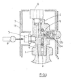
- the ambulation assembly of the invention formed of a small compressed oxygen cylinder on which is mounted a mini integrated pressure reducing valve according to the invention will now be described in more detail with the aid of an exemplary embodiment, which is illustrated in the figures appended hereto.
- the walking equipment of the invention provided with the regulator valve 2 of the invention is connected to a valve 14 on demand equipped with an oxygen therapy bezel 15;
- an oxygen therapy bezel 15 an oxygen therapy bezel
- the portable ambulatory equipment of the invention forms an autonomous unit for proximity walking to provide a controlled flow of oxygen to a patient, at each inspiration of the user, via a valve 14 on demand equipped with an oxygen therapy bezel 15.
- the oxygen is stored in the form of compressed gas in a small gas cylinder 1 on which is mounted the valve-expansion valve assembly 2 of the invention to which a valve 14 is connected on demand.
- the filling of the small bottle 1 with compressed gas at high pressure is done through the specific connection 5 of the regulator valve 2, thanks to an external connector 6.
- the walking assembly of the invention which is composed here of a bottle 1 of very small size, typically of a height of less than 30 cm, for high pressure compressed gas, in particular oxygen, medical grade, on which is mounted the integrated pressure regulator valve assembly 2 of the invention comprising an internal filter 3 for protecting the entire valve, a residual pressure valve 4, an accessible gas charging plug or inlet 5 by a filling connector 6 through a protective cowling 7 to protect the valve-regulator assembly 2 against shocks, a pressure gauge 8 to view the pressure available in the bottle, a valve 9 for isolating the bottle whose operation is detailed below, detent means comprising a first expansion stage 10 on the Figure 2 equipped with a safety valve 11 and a second expansion stage 12.
- Said first 10 and second 12 stages of expansion comprise conventional expansion members, such as valves, valve seats, spring means ..., allowing the gas to be relieved from its high pressure, that is to say say the pressure of the gas at the bottle outlet, for example 200 bar, to its low pressure, that is to say its operating pressure, for example 1 bar, after passing through an intermediate pressure.
- conventional expansion members such as valves, valve seats, spring means ...
- the valve-expansion valve assembly also comprises a specific output interface 13 for connecting the demand valve 14, said connection allowing the unlocking of the rotary member 18 of the valve 9, that is to say that the The valve 9 can not be opened without first connecting the valve 14 to it, as explained below.
- the oxygen therapy bezel 15 is connected to the outlet of the valve 14 on demand so as to supply the patient with oxygen whose pressure has been reduced in the two stages 10, 12 of relaxation. Indeed, such a dual-pressure reduction system 10, 12 ensures a constant flow rate regardless of the filling level of the bottle.
- valve-expander assembly of the invention comprises an optional means operable by the user to temporarily increase the oxygen flow rate subsequent to its activation, for example a button 12b actuated by digital pressure and to compress the expansion spring of the piston of the second stage 12 of expansion to temporarily increase the pressure relaxed during the support time, in order to obtain an increase in oxygen flow rate adapted to the additional efforts of the patient.
- an optional means operable by the user to temporarily increase the oxygen flow rate subsequent to its activation for example a button 12b actuated by digital pressure and to compress the expansion spring of the piston of the second stage 12 of expansion to temporarily increase the pressure relaxed during the support time, in order to obtain an increase in oxygen flow rate adapted to the additional efforts of the patient.
- the valve further comprises a safety valve 11 for evacuating any overpressure in the event of failure of the first expansion valve of the first expansion stage.
- valve regulator assembly 2 is provided with a specific output interface carrying the locking valve 9 controlling the gas inlet and the gas outlet, said outlet interface being, furthermore, intended to receive a device 14 using the oxygen at reduced pressure delivered by the assembly 2, such as a flow meter, a valve on demand or an opening tool necessary to purge the gas from the bottle ,.
- a device 14 using the oxygen at reduced pressure delivered by the assembly 2 such as a flow meter, a valve on demand or an opening tool necessary to purge the gas from the bottle ,.
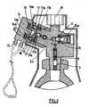
- the input interface of the apparatus 14 using the gas cooperates with the output interface of the valve-regulator assembly 2 so as to releasing the rotation of the rotary actuating member 18, such as a ring or flywheel, of the locking valve 9, as illustrated in FIGS. Figures 2 to 4 .
- the opening of the locking valve 9, that is to say the release of the gas can only be done once the apparatus of use 14 connected to the pressure-reducing valve 2.
- the utilization apparatus 14 comprises an input interface, acting as a connection socket, complementary to the specific output interface of the regulator valve 2, cooperating with each other, so as not to release the gas only when they are connected to one another, thanks to the presence of a locking valve 9 whose 18 maneuvering member is operable only after adequate connection of these parts one to the other.
- the user selects a full bottle 1 by checking the indication of the pressure gauge 8, removes the protective film which protects the output interface of the regulator valve assembly 2 intended to receive the input interface of the valve on demand 14.
- connection interface of the demand valve 14 into the central orifice of the assembly 13 provided with the locking valve 9, which releases the operating member 18 of the locking valve 9 and then allows the release of the gas.
- the unlocking of the rotation of the operating member 18 is obtained by the action in repulsion of one or more pins, lugs or the like 14a carried by the demand valve 14 on one or more pins 17, balls or similar blocking, housed in the body of the valve-expansion valve and acting on the control ring 18 of the locking valve 9.
- each pin 17 being movable in its housing 17b partially projecting from said housing 17b under the effect of an elastic thrust exerted on it a spring means 17a located between said pin 17 and the bottom of the housing 17b where is inserted the pin 17 as schematized on the figure 2 .
- each pin 17 protruding from the housing 17b is housed in a recess or housing 28, adapted dimensioning, arranged in the actuating member 18, which blocks the rotation of said actuating member 18 forming a ring around the tap 9.
- the recesses or recesses 28 are holes or orifices which pass through the entire wall of the actuating ring 18.
- Which ring 18 thus released can then be operated in rotation by the operator to its limited open position by a stop and this, in order to open the valve 9 and release the gas, the drive of the valve 9 being made of coupled with a rotation of the valve 14 about its axis. The whole is then ready to deliver gas.
- valve 14 As soon as the valve 14 is rotated to the "open tap” position, it can no longer be disconnected.
- the gas arrives in the first expansion valve consisting of a piston 10 and a valve 11 to be relaxed from its high pressure. to a lower pressure, called intermediate pressure or average pressure.
- the gas expanded at the intermediate pressure arrives on the second expansion valve consisting of a valve 12 and piston 12a where it is expanded from the mean pressure to low pressure, commonly called final pressure or operating pressure.
- the final pressure level can at any time be increased by the user with the support of a button 12b compressing a little more relaxation spring of the second relaxation stage.
- a system making it possible to temporarily increase the flow rate by simply pressing a button 12a is an interesting optional feature because this increase in flow rate can be controlled directly by the patient himself when he feels the need, for example when he makes a greater effort, including climbing a hill or a staircase.
- the final pressure obtained communicates through the internal gas passage to a housing 13 opening at the outlet port carried by the outlet interface, which housing 13 is provided to receive a portion of the valve 14 or any other device to be connected to it.
- valve 14 oriented in the valve through the recesses 113a makes it possible to push the pins 17 back on elastic means 17a thanks to two pins 14a integral with the input interface of the valve 14, which releases the rotation of the ring 18, the latter then being angularly connected to the valve 14.
- the rotation of the valve 14 therefore drives the ring 18, the ramps 18a, 18b act on the slide 9 which moves transversely and allows the opening or closing of the valve in the direction of rotation of the valve.
- the outlet of the valve 14 is connected to an oxygen therapy bezel 15 and when the patient inhales, the demand valve opens and gives the prescribed flow that has been defined by a nozzle in the valve during its manufacture.
- a double action rupture disc inside the body of the expansion valve assembly 2 is also preferably incorporated a double action rupture disc, as described in the document FR 0211318 or the document US Patent 4,706,698 intended to overcome any untimely increase in pressure due to an intense source of heat, as well as a residual pressure valve guaranteeing a minimum pressure of emptying the bottle, thus avoiding, on the one hand, any retro-pollution by impurities at the end of use, when the bottle is empty or almost and a second rinse when filling the bottle with a new charge of gas.
- the whole of the invention is packaged and ready for use, either individually or as a pack of several bottles, and is preferably covered with a protective film 16 avoiding it being soiled during transport, for example the standardized color of the gas contained in the bottle 1, and including all the legal indications on the definition of said gas.
- the nasal breathing goggles and the demand valve 14 are held by the patient user who never separates from them because the equipment is suitable for a flow rate in accordance with the prescription provided by his physician.
- valve regulator / cylinder assembly of the invention after use of all the gas by the patient, is returned to the gas distributor for its filling gas. Once refilled, the valve regulator / bottle assembly is subjected to a filming and packing operation before being re-shipped.
Landscapes
- Engineering & Computer Science (AREA)
- General Engineering & Computer Science (AREA)
- Mechanical Engineering (AREA)
- Filling Or Discharging Of Gas Storage Vessels (AREA)
- Respiratory Apparatuses And Protective Means (AREA)
- Preventing Unauthorised Actuation Of Valves (AREA)
- Safety Valves (AREA)
- Fluid-Damping Devices (AREA)
- Magnetically Actuated Valves (AREA)
- Braking Arrangements (AREA)
Abstract
Description
La présente invention concerne un ensemble robinet à détendeur intégré, ainsi qu'un équipement de déambulation comprenant un tel ensemble robinet à détendeur intégré monté sur une petite bouteille de gaz comprimé dont l'ouverture et l'utilisation ne sont possibles que si un appareil d'utilisation pour délivrer du gaz, tel qu'un débitmètre, une valve respiratoire, un outil d'ouverture nécessaire pour effectuer la purge de la bouteille ou tout autre appareil utilisant le gaz, y est connecté via une interface spécifique de connexion permettant de libérer un verrou bloquant la rotation de l'organe de manipulation du robinet commandant l'ouverture du gaz et sa libération.The present invention relates to an integrated pressure regulator valve assembly, and a strolling equipment comprising such an integrated pressure regulator valve assembly mounted on a small bottle of compressed gas whose opening and use are possible only if a device use for delivering gas, such as a flow meter, a breathing valve, an opening tool necessary for purging the bottle or any other apparatus using the gas, is connected thereto via a specific connection interface for releasing a lock blocking the rotation of the manipulator member of the valve controlling the opening of the gas and its release.
Il existe actuellement des équipements de déambulation qui utilisent des sources de gaz comprimé ou d'oxygène liquide.There are currently walking equipment that uses sources of compressed gas or liquid oxygen.
Les sources d'oxygène liquide sont généralement de plus petite taille et ont une autonomie supérieure qui est souvent surdimensionnée pour les déambulations de proximité.Liquid oxygen sources are generally smaller in size and have greater autonomy, which is often oversized for proximity wandering.
Toutefois, l'utilisation d'oxygène liquide n'est pas idéale car l'évaporation du liquide engendre des pertes de gaz et recourir à de l'oxygène liquide n'est pas avantageux, compte tenu de son prix, lorsque la déambulation du patient est de courte durée.However, the use of liquid oxygen is not ideal because the evaporation of the liquid generates losses of gas and use of liquid oxygen is not advantageous, given its price, when the ambulation of the patient is short-lived.
Par ailleurs, les équipements existant faisant appel à une source de gaz comprimé sont peu pratiques, encombrants et souvent trop lourds pour les patients ayant recours à ce type de traitement puisque ceux-ci sont souvent des personnes âgées ou affaiblies.Furthermore, existing equipment using a source of compressed gas is impractical, cumbersome and often too heavy for patients using this type of treatment since they are often elderly or weakened.
De plus, l'utilisation de tels équipements nécessite l'emploi de régulateurs de pression dont l'interface avec la bouteille est soumise à des pressions très élevées, c'est-à-dire de l'ordre de 200 bar, ce qui requiert une mise en oeuvre pénible et délicate pour l'utilisateur, n'est pas sans danger, en particulier en cas de mauvaise connexion, d'entretien insuffisant ou de présence involontaire de particules grasses sur les zones soumises à la haute pression.In addition, the use of such equipment requires the use of pressure regulators whose interface with the bottle is subjected to very high pressures, that is to say of the order of 200 bar, which requires a painful and delicate implementation for the user, is not without danger, in particular in case of poor connection, insufficient maintenance or unintentional presence of greasy particles on the areas subjected to high pressure.
Par ailleurs, l'utilisation de ces sources s'effectue généralement soit avec débitmètres, soit des valves à la demande à commande électronique ou de valves à commande pneumatique.In addition, the use of these sources is generally carried out either with flow meters, or electronically controlled demand valves or pneumatically operated valves.
Or, les valves à commande électronique nécessitent une énergie supplémentaire fournie par une pile ou des accumulateurs, qui doit être disponible au moment de l'utilisation, ce qui n'est pas toujours le cas.However, electronically controlled valves require additional energy provided by a battery or accumulators, which must be available at the time of use, which is not always the case.
Les valves à commande pneumatique utilisent, quant à elles, l'énergie du gaz stocké pour l'ouverture principale et l'inspiration de l'utilisateur en tant qu'ordre de déclenchement. De ce fait, elles sont souvent plus pratiques, plus compactes et plus légères que les valves à énergie électrique.Pneumatic valves use the stored gas energy for the main opening and the user's inspiration as a triggering order. As a result, they are often more practical, more compact and lighter than electric energy valves.
Le document
Le but de la présente invention est de proposer, d'une part, un équipement de distribution de gaz, en particulier d'oxygène médical, qui soit léger, pratique, bien adapté à la déambulation des patients, d'une conception compacte permettant d'optimiser le poids total de l'ensemble, de minimiser au maximum les efforts de connexion, de supprimer toute intervention sur des parties soumises à la haute pression et donc de limiter les risques afférents, ainsi que de proposer, d'autre part, un robinet à détendeur intégré qui soit amélioré au plan de la sécurité par rapport aux robinets détendeurs existants et qui puisse faire partie d'un tel équipement de déambulation, lorsqu'il est monté sur une petite bouteille de gaz, en particulier une bouteille d'oxygène médical.The object of the present invention is to provide, on the one hand, a gas dispensing equipment, in particular medical oxygen, which is light, practical, well adapted to the ambulation of patients, a compact design allowing optimize the overall weight of the assembly, minimize connection efforts, eliminate any intervention on parts subject to high pressure and thus limit the associated risks, and propose, on the other hand, a integrated regulator valve that is improved in safety over existing expansion valves and can be part of such ambulatory equipment when mounted on a small gas cylinder, particularly a medical oxygen cylinder.
La solution de l'invention est alors un ensemble robinet à détendeur intégré avec un corps principal comportant:
- un passage interne de gaz permettant de véhiculer du gaz entre un orifice d'entrée de gaz et un orifice de sortie de gaz,
- des moyens de détente de gaz agencés sur ledit passage interne de gaz entre lesdits orifice d'entrée de gaz et orifice de sortie de gaz, et
- un robinet de verrouillage servant à contrôler la libération du gaz et comprenant un organe d'actionnement rotatif, manoeuvrable par l'utilisateur, l'ensemble comprenant, en outre, des moyens de blocage agissant sur l'organe d'actionnement rotatif du robinet de verrouillage de manière à empêcher normalement toute rotation dudit l'organe d'actionnement, les moyens de blocage comprenant un ou plusieurs pièces mobiles venant coopérer avec l'organe d'actionnement de manière à empêcher sa rotation et la libération du gaz, la solution selon l'invention est caractérisée en ce que l'organe d'actionnement est centré sur un bossage du corps du robinet, ledit bossage portant, en outre, l'orifice de sortie de gaz permettant de distribuer le gaz et des moyens de connexion permettant le raccordement d'un appareil d'utilisation du gaz muni d'une interface d'entrée et de moyens de connexion complémentaires aptes à coopérer avec les moyens de connexion du bossage l'interface d'entrée dudit appareil d'utilisation du gaz étant conformée pour agir sur la au moins une pièce mobile des moyens de blocage pour libérer la rotation de l'organe d'actionnement, après raccordement de l'interface d'entrée de l'appareil d'utilisation du gaz sur l'interface de sortie du robinet.
- an internal gas passage for conveying gas between a gas inlet and a gas outlet,
- gas expansion means arranged on said internal gas passage between said gas inlet and gas outlet port, and
- a locking valve for controlling the release of the gas and comprising a rotatable actuator operable by the user, the assembly further comprising locking means acting on the rotary actuating member of the locking so as to normally prevent any rotation of said actuating member, the locking means comprising one or more moving parts cooperating with the actuating member so as to prevent its rotation and the release of the gas, the solution according to the invention is characterized in that the actuating member is centered on a boss of the valve body, said boss carrying, in addition, the gas outlet orifice for dispensing the gas and connection means allowing the connection of a gas utilization apparatus provided with an input interface and complementary connection means adapted to cooperate with the connection means of the boss the input interface e of said apparatus for using the gas being shaped to act on the at least one moving part of the locking means to release the rotation of the actuating member, after connection of the input interface of the apparatus of use of the gas on the valve outlet interface.
Selon le cas, l'ensemble de l'invention peut comprendre l'une ou plusieurs des caractéristiques techniques suivantes :
- au moins une pièce mobile est repoussée par des moyens élastiques en direction de la bague de manière à venir se loger, au moins partiellement, dans au moins un évidement aménagé dans l'organe d'actionnement et dimensionné pour recevoir au moins une partie de ladite pièce mobile de manière à empêcher la rotation de l'organe d'actionnement lorsqu'une pièce mobile est au moins partiellement logée dans un évidement.
- l'organe d'actionnement est une bague rotative.
- le ou les moyens élastiques sont des ressorts.
- la ou les pièces mobiles sont des pions, des billes ou analogues.
- les moyens de détente de gaz comportent un premier étage de détente et un deuxième étage de détente agencés sur ledit passage interne de gaz, le deuxième étage de détente étant situé en aval du premier étage de détente.
- il comporte, en outre : une soupape à pression résiduelle, un manomètre permettant de visualiser la pression disponible dans la bouteille, un raccord de remplissage, un filtre, et/ou une soupape de sécurité permettant d'évacuer toute surpression éventuelle en cas de défaillance ou de rupture du clapet de première détente du premier étage de détente.
- il comporte, en outre, un moyen d'action instantané, activable par l'opérateur, agissant sur les moyens de détente du deuxième étage de détente de manière à augmenter instantanément la pression détendue et le débit de gaz délivré, durant le temps d'activation dudit moyen par l'opérateur, de préférence le moyen d'action instantané est un bouton venant comprimer le ressort de détente du piston du deuxième étage de détente.
- at least one moving part is pushed by elastic means in the direction of the ring so as to be housed, at least partially, in at least one recess arranged in the actuating member and dimensioned to receive at least a portion of said moving part so as to prevent the rotation of the actuating member when a movable part is at least partially housed in a recess.
- the actuating member is a rotating ring.
- the elastic means or means are springs.
- the one or more moving parts are pions, balls or the like.
- the gas expansion means comprise a first expansion stage and a second expansion stage arranged on said internal gas passage, the second expansion stage being located downstream of the first expansion stage.
- it further comprises: a residual pressure valve, a manometer for visualizing the pressure available in the bottle, a filling connector, a filter, and / or a safety valve to evacuate any excess pressure in case of failure. or breaking the first expansion valve of the first expansion stage.
- it comprises, in addition, an instantaneous action means, activatable by the operator, acting on the expansion means of the second expansion stage so as to instantly increase the relaxed pressure and the delivered gas flow, during the time of activation of said means by the operator, preferably the instantaneous action means is a button for compressing the expansion spring of the piston of the second expansion stage.
L'invention porte aussi sur un équipement portatif de déambulation dont le poids est inférieur à 2 kg, comprenant une bouteille de gaz comprimé sur laquelle est monté un ensemble robinet à détendeur intégré selon l'invention, de préférence la bouteille de gaz contient de l'oxygène.The invention also relates to portable ambulatory equipment whose weight is less than 2 kg, comprising a compressed gas cylinder on which is mounted an integrated pressure regulator valve assembly according to the invention, preferably the gas cylinder contains 'oxygen.
Selon le cas, l'équipement portatif de l'invention peut comprendre l'une ou plusieurs des caractéristiques techniques suivantes :
- il comprend, en outre, un appareil d'utilisation du gaz raccordé, via son interface d'entrée, à l'interface de sortie du robinet, ledit appareil d'utilisation du gaz comprenant des moyens de connexion complémentaires coopérant avec les moyens de connexion de l'interface de sortie du robinet et avec les moyens de blocage agissant sur l'organe d'actionnement de manière à autoriser la rotation de l'organe d'actionnement et le passage du gaz du robinet-détendeur vers l'appareil d'utilisation du gaz.
- l'appareil d'utilisation du gaz est choisi parmi les valves à la demande ou les débitmètres.
- il comporte un capotage de protection agencé de manière à protéger l'ensemble robinet à détendeur intégré, de préférence ledit capotage de protection est fixé sur le robinet
- it further comprises an apparatus for using the connected gas, via its input interface, at the outlet interface of the tap, said apparatus for using the gas comprising complementary connection means cooperating with the connection means of the outlet interface of the valve and with the locking means acting on the actuating member so as to allow the rotation of the actuating member and the passage of the gas from the pressure-reducing valve to the apparatus of use of gas.
- the apparatus for using the gas is chosen from the valves on demand or the flow meters.
- it comprises a protective cowling arranged so as to protect the integral pressure reducing valve assembly, preferably said protective cowling is fixed on the tap
L'ensemble de déambulation de l'invention formé d'une petite bouteille d'oxygène comprimé sur laquelle est monté un mini robinet détendeur intégré selon l'invention va maintenant être décrit plus en détail à l'aide d'un exemple de réalisation, lequel est illustré sur les figures ci-annexées.The ambulation assembly of the invention formed of a small compressed oxygen cylinder on which is mounted a mini integrated pressure reducing valve according to the invention will now be described in more detail with the aid of an exemplary embodiment, which is illustrated in the figures appended hereto.
Dans l'exemple des
L'équipement portatif de déambulation de l'invention, illustré par les
L'oxygène est stocké sous forme de gaz comprimé dans une petite bouteille 1 de gaz sur laquelle est monté l'ensemble robinet-détendeur 2 de l'invention auquel vient se raccorder une valve 14 à la demande.The oxygen is stored in the form of compressed gas in a small gas cylinder 1 on which is mounted the valve-
Le remplissage de la petite bouteille 1 en gaz comprimé à haute pression se fait au travers du raccord spécifique 5 du robinet détendeur 2, grâce à un connecteur externe 6.The filling of the small bottle 1 with compressed gas at high pressure is done through the specific connection 5 of the
Sur la
Lesdits premier 10 et deuxième 12 étages de détente comprennent des organes de détente classiques, tels que clapets, sièges de clapets, moyens à ressort..., permettant d'effectuer une détente du gaz depuis sa pression haute, c'est-à-dire la pression du gaz en sortie de bouteille, par exemple 200 bar, jusqu'à sa pression basse, c'est-à-dire sa pression d'utilisation, par exemple 1 bar, après passage par une pression intermédiaire.Said first 10 and second 12 stages of expansion comprise conventional expansion members, such as valves, valve seats, spring means ..., allowing the gas to be relieved from its high pressure, that is to say say the pressure of the gas at the bottle outlet, for example 200 bar, to its low pressure, that is to say its operating pressure, for example 1 bar, after passing through an intermediate pressure.
L'ensemble robinet-détendeur comprend également une interface de sortie 13 spécifique servant à la connexion de la valve à la demande 14, ladite connexion permettant le déverrouillage de l'organe rotatif 18 du robinet 9, c'est-à-dire que l'on ne peut pas ouvrir le robinet 9 sans y raccorder au préalable la valve 14, comme expliqué ci-après.The valve-expansion valve assembly also comprises a
La lunette 15 d'oxygénothérapie est reliée à la sortie de la valve 14 à la demande de manière à alimenter le patient en oxygène dont la pression a été réduite dans les deux étages 10, 12 de détente. En effet, un tel système de réduction de la pression à double détente 10, 12 permet de garantir un niveau de débit constant quel que soit le niveau de remplissage de la bouteille.The
Avantageusement, l'ensemble robinet-détendeur de l'invention comprend un moyen optionnel actionnable par l'utilisateur permettant d'augmenter momentanément le débit d'oxygène délivré subséquemment à son activation, par exemple un bouton 12b actionnable par pression digitale et permettant de comprimer le ressort de détente du piston du deuxième étage 12 de détente afin d'augmenter momentanément la pression détendue pendant le temps d'appui, dans le but d'obtenir une augmentation du débit d'oxygène adaptée aux efforts supplémentaires du patient.Advantageously, the valve-expander assembly of the invention comprises an optional means operable by the user to temporarily increase the oxygen flow rate subsequent to its activation, for example a
Le robinet comporte par ailleurs une soupape de sécurité 11 permettant d'évacuer une surpression éventuelle en cas de défaillance du clapet de première détente du premier étage 10 de détente.The valve further comprises a
Plus spécifiquement, l'ensemble robinet détendeur 2 est doté d'une interface de sortie spécifique portant le robinet de verrouillage 9 commandant l'entrée et la sortie du gaz, ladite interface de sortie étant, en outre, destinée à recevoir un appareil 14 utilisant l'oxygène à pression réduite délivré par l'ensemble 2, tel qu'un débitmètre, une valve à la demande ou un outil d'ouverture nécessaire pour effectuer la purge du gaz de la bouteille,.More specifically, the
Selon l'invention, l'interface d'entrée de l'appareil 14 utilisant le gaz, c'est-à-dire sa prise de connexion, coopère avec l'interface de sortie de l'ensemble robinet-détendeur 2 de manière à libérer la rotation de l'organe 18 de manoeuvre rotatif, telle une bague ou volant, du robinet de verrouillage 9, comme illustré sur les
Ainsi, l'ouverture du robinet de verrouillage 9, c'est-à-dire la libération du gaz, ne peut se faire qu'une fois l'appareil d'utilisation 14 connecté sur le robinet-détendeur 2.Thus, the opening of the
Autrement dit, l'appareil d'utilisation 14 comporte une interface d'entrée, faisant office de prise de connexion, complémentaire de l'interface de sortie spécifique du robinet détendeur 2, coopérant l'une avec l'autre, de manière à ne libérer le gaz que lorsqu'elles sont raccordées l'une à l'autre, grâce à la présence d'un robinet de verrouillage 9 dont l'organe 18 de manoeuvre n'est manoeuvrable qu'après raccordement adéquat de ces parties l'une à l'autre.In other words, the
En fait, la mise en oeuvre d'un ensemble 2 de l'invention se fait comme suit.In fact, the implementation of a
Tout d'abord, l'utilisateur sélectionne une bouteille 1 pleine en vérifiant l'indication du manomètre 8, enlève le film de protection qui protége l'interface de sortie de l'ensemble robinet détendeur 2 prévue pour recevoir l'interface d'entrée de la valve à la demande 14.Firstly, the user selects a full bottle 1 by checking the indication of the
Comme montré sur la
Plus précisément, le déverrouillage de la rotation de l'organe de manoeuvre 18 s'obtient par l'action en répulsion d'un ou plusieurs picots, ergots ou analogues 14a portés par la valve à la demande 14 sur un ou plusieurs pions 17, billes ou analogues de blocage, logés dans le corps de l'ensemble robinet-détendeur et agissant sur la bague de commande 18 du robinet de verrouillage 9.More specifically, the unlocking of the rotation of the operating
En effet, pour empêcher toute rotation de l'organe de manoeuvre 18, encore appelé organe d'actionnement 18, lorsque aucun appareil 14 n'y est raccordé, sont prévus un ou plusieurs pions 17, billes ou analogues de blocage, chaque pion 17 étant mobile dans son logement 17b en faisant partiellement saillie hors dudit logement 17b sous l'effet d'une poussée élastique qu'exerce sur lui un moyen à ressort 17a situé entre ledit pion 17 et le fond du logement 17b où est inséré le pion 17, comme schématisé sur la
La partie de chaque pion 17 faisant saillie hors du logement 17b vient se loger dans un évidement ou logement 28, de dimensionnement adapté, aménagé dans l'organe de manoeuvre 18, ce qui bloque la rotation dudit organe d'actionnement 18 formant bague autour du robinet 9.The portion of each
Comme on le voit sur la
Par contre, lorsqu'un appareil 14 est raccordé à l'ensemble robinet-détendeur 2 de l'invention, les picots ou ergots 14a portés par l'interface d'entrée dudit appareil 14 viennent contre-agir sur des pions 17 complémentaires, dans un sens tendant à les dégager des orifices 28 de la bague 18, donc à les repousser vers leurs logements 17b, ce qui comprime les ressorts 17a, et permet de libérer la bague rotative 18 qui est normalement bloquée dans ces pions 17.On the other hand, when an
Laquelle bague 18 ainsi libérée peut alors être manoeuvrée en rotation par l'opérateur jusque dans sa position d'ouverture limitée par une butée et ce, afin d'ouvrir le robinet 9 et libérer le gaz, l'entraînement du robinet 9 se faisant de manière couplée à une rotation de la valve 14 autour de son axe. L'ensemble est alors prêt à délivrer du gaz.Which
Dès la rotation de la valve 14 jusqu'à la position "robinet ouvert", celle-ci ne peut plus être déconnectée.As soon as the
En effet, les pions 19 passent dans la gorge 20 de l'interface de la valve 14. Cette dernière est donc prisonnière du système jusqu'à ce que l'utilisateur manoeuvre la valve 14 en position inverse jusqu'en butée.Indeed, the
Lorsque le robinet 9 est ouvert, c'est-à-dire après raccordement de l'appareil 14, le gaz arrive dans le détendeur de première détente composé d'un piston 10 et d'une soupape 11 pour être détendu depuis sa pression haute jusqu'à une pression plus basse, appelée pression intermédiaire ou pression moyenne.When the
Ensuite, le gaz détendu à la pression intermédiaire arrive sur le détendeur de seconde détente composé d'un clapet 12 et piston 12a où il est détendu depuis la pression moyenne jusqu'à basse pression, couramment appelée pression finale ou pression d'utilisation.Then, the gas expanded at the intermediate pressure arrives on the second expansion valve consisting of a
Toutefois, le niveau de pression finale peut à tout moment être augmenté par l'utilisateur grâce à l'appui sur un bouton 12b comprimant un peu plus le ressort de détente du deuxième étage de détente. Autrement dit, la possibilité de disposer, au niveau du second étage de détente 12, d'un système permettant d'augmenter momentanément le débit par simple pression sur un bouton 12a est une caractéristique optionnelle intéressante car cette augmentation de débit peut être commandée directement par le patient lui-même lorsqu'il en ressent le besoin, par exemple lorsqu'il effectue un effort plus important, notamment en montant une côte ou un escalier.However, the final pressure level can at any time be increased by the user with the support of a
Dans tous les cas, la pression finale obtenue communique par le passage interne de gaz jusqu'à un logement 13 débouchant au niveau de l'orifice de sortie porté par l'interface de sortie, lequel logement 13 est prévu pour recevoir une partie de la valve 14 ou tout autre appareil devant y être raccordé.In all cases, the final pressure obtained communicates through the internal gas passage to a
Comme expliqué ci-avant, l'introduction de la valve 14 orientée dans le robinet au travers des évidements 113a permet de repousser les pions 17 en rappel sur des moyens élastiques 17a grâce à deux pions 14a solidaires de l'interface d'entrée de la valve 14, ce qui libère la rotation de la bague 18, celle-ci étant alors liée angulairement à la valve 14.As explained above, the introduction of the
Lors de la rotation manuelle de la valve 14 des ergots 19 permettent de rendre l'interface de la valve 14 prisonnière de l'organe 18 d'actionnement du robinet 9, c'est-à-dire la bague 18.During the manual rotation of the
La rotation de la valve 14 entraîne donc la bague 18, les rampes 18a, 18b agissent sur le tiroir 9 qui se déplace transversalement et permet l'ouverture ou la fermeture du robinet selon le sens de rotation de la valve.The rotation of the
La sortie de la valve 14 est reliée à une lunette d'oxygénothérapie 15 et lorsque le patient inspire, la valve à la demande se met en ouverture et donne le débit prescrit qui a été défini par un ajutage dans la valve lors de sa fabrication.The outlet of the
En outre, à l'intérieur du corps de l'ensemble robinet détendeur 2 est également préférentiellement incorporé un disque de rupture à double action, tel que décrit dans le document
L'ensemble de l'invention est conditionné et prêt à l'emploi, soit individuellement, soit en paquet de plusieurs bouteilles, et est préférentiellement recouvert d'un film de protection 16 évitant qu'il ne soit sali durant le transport, par exemple de la couleur normalisée du gaz contenu dans la bouteille 1, et comportant toutes les indications légales sur la définition dudit gaz.The whole of the invention is packaged and ready for use, either individually or as a pack of several bottles, and is preferably covered with a
Les lunettes 15 respiratoires nasales et la valve à la demande 14 sont détenues par l'utilisateur patient qui ne s'en sépare jamais car le matériel est adapté pour un débit conforme à la prescription fournie par son médecin.The nasal breathing goggles and the
L'ensemble robinet détendeur/bouteille de l'invention, après utilisation de la totalité du gaz par le patient, est retourné chez le distributeur de gaz pour son remplissage en gaz. Une fois re-rempli, l'ensemble robinet détendeur/bouteille est soumis à une opération de filmage et emballage avant sa ré-expédition.The valve regulator / cylinder assembly of the invention, after use of all the gas by the patient, is returned to the gas distributor for its filling gas. Once refilled, the valve regulator / bottle assembly is subjected to a filming and packing operation before being re-shipped.
Claims (12)
- Valve unit with built-in pressure reducer (2) with a main body comprising:- an internal gas passage for conveying gas between a gas inlet port and a gas outlet port,- gas expansion means (10, 12) arranged on the said internal gas passage between the said gas inlet port and gas outlet port, and- a locking tap (9) for controlling the release of the gas and comprising a rotary actuating member (18), manoeuvrable by the user,the unit further comprising blocking means (17) acting on the rotary actuating member (18) of the locking tap (9) so as to normally prevent any rotation of the said actuating member (18), the blocking means (17) comprising one or more moving parts which cooperate with the actuating member (18) to prevent its rotation and the release of the gas,
characterized in that the actuating member (18) is centred on a boss (2a) of the body of the said valve unit (2), the said boss (2a) further containing the gas outlet port (13) for distributing the gas and connecting means (19) for connecting a gas-use apparatus (14) provided with an inlet interface (13a) and complementary connecting means (20) suitable for cooperating with the connecting means (19) of the boss, the inlet interface (13a) of the said gas-use apparatus being conformed to counteract on the at least one moving part (17) of the blocking means to liberate the rotation of the actuating member (18), after connection of the inlet interface (13a) of the gas-use apparatus (14) to the outlet interface of the said valve unit (2). - Unit according to Claim 1, characterized in that the actuating member (18) is a ring gauge.
- Unit according to Claim 2, characterized in that at least one moving part (17) is pushed back by elastic means (17a) towards the ring (18) in order to be lodged, at least partially, in at least one recess (28) arranged in the actuating member (18) and dimensioned to accommodate at least part of the said moving part (17) to prevent the rotation of the actuating member (18) when a moving part (17) is at least partially lodged in a recess (28).
- Unit according to Claim 3, characterized in that the elastic means (17a), of which there may be more than one, are springs.
- Unit according to one of Claims 1 to 4, characterized in that the moving part or parts (17) are pins, balls or similar.
- Unit according to one of Claims 1 to 5, characterized in that the gas expansion means (10, 12) comprise a first expansion stage (10) and a second expansion stage (12) arranged on the said internal gas passage, the second expansion stage (12) being located downstream of the first expansion stage (10).
- Unit according to one of Claims 1 to 6, characterized in that it further comprises:- a residual pressure valve (4),- a pressure gauge (8) for visualizing the pressure available in the cylinder,- a filling coupling (5),- a filter (3), and/or- a relief valve (11) for removing any overpressure in case of failure or of breakage of the first expansion check valve of the first expansion stage (10).
- Unit according to one of Claims 1 to 7, characterized in that it further comprises instantaneous action means (12b), which can be activated by the operator, acting on the expansion means of the second expansion stage (12), in order to instantaneously increase the expanded pressure and the flow rate of gas delivered, during the time of activation of the said means (12) by the operator, preferably the instantaneous action means is a knob (12b) which compresses the expansion spring of the piston of the second expansion stage (12).
- Portable travelling equipment having a weight lower than 2 kg, comprising a compressed-gas cylinder (1) on which a valve unit with built-in pressure reducer (2) is mounted according to one of Claims 1 to 8, preferably the gas cylinder (1) contains oxygen.
- Portable equipment according to Claim 9, characterized in that it further comprises a gas-use apparatus (14) connected, via its inlet interface (13a), to the outlet interface (13) of the said valve unit (2), the said gas-use apparatus (14) comprising complementary connecting means (20) cooperating with the connecting means (19) of the outlet interface (13) of the said valve unit (2) and with the blocking means (17) acting on the actuating member (18) in order to allow the rotation of the actuating member (18) and the passage of the gas from the said valve unit (2) to the gas-use apparatus (14).
- Portable equipment according to Claim 10, characterized in that the gas-use apparatus (14) is selected from demand valves or flowmeters.
- Portable equipment according to Claim 9, characterized in that it comprises a protective cover arranged in order to protect the valve unit with built-in pressure reducer, preferably the said protective cover is fixed to the said valve unit (2).
Applications Claiming Priority (2)
| Application Number | Priority Date | Filing Date | Title |
|---|---|---|---|
| FR0350495 | 2003-09-03 | ||
| FR0350495A FR2859289B1 (en) | 2003-09-03 | 2003-09-03 | INTEGRATED VALVATOR-VALVE WITH MEANS FOR LOCKING THE ACTUATOR |
Publications (2)
| Publication Number | Publication Date |
|---|---|
| EP1512895A1 EP1512895A1 (en) | 2005-03-09 |
| EP1512895B1 true EP1512895B1 (en) | 2009-03-11 |
Family
ID=38669577
Family Applications (1)
| Application Number | Title | Priority Date | Filing Date |
|---|---|---|---|
| EP20040300557 Expired - Lifetime EP1512895B1 (en) | 2003-09-03 | 2004-08-26 | Integrated expansion valve with means for locking the actuator |
Country Status (7)
| Country | Link |
|---|---|
| US (1) | US7287548B2 (en) |
| EP (1) | EP1512895B1 (en) |
| JP (1) | JP2005074231A (en) |
| AT (1) | ATE425398T1 (en) |
| AU (1) | AU2004208658A1 (en) |
| DE (1) | DE602004019857D1 (en) |
| FR (1) | FR2859289B1 (en) |
Families Citing this family (15)
| Publication number | Priority date | Publication date | Assignee | Title |
|---|---|---|---|---|
| US8011380B2 (en) * | 2009-10-01 | 2011-09-06 | Vision Tech International Llp | Single component two-stage regulator |
| FR2979718B1 (en) | 2011-09-01 | 2013-09-20 | Hampiaux S A S | GAS REGULATOR ON ONE FLOOR |
| WO2015036663A1 (en) * | 2013-09-12 | 2015-03-19 | L'air Liquide, Societe Anonyme Pour L'etude Et L'exploitation Des Procedes Georges Claude | Assembly comprising a protective casing and a gas cylinder with a device for indicating pressure or autonomy in the up position |
| FR3018580B1 (en) * | 2014-03-12 | 2018-11-02 | L'air Liquide, Societe Anonyme Pour L'etude Et L'exploitation Des Procedes Georges Claude | BLOCK TAP FOR GAS CONTAINER WITH HIGH PRESSURE PRESSURE INDICATOR OR AUTONOMY DEVICE |
| FR3025585B1 (en) * | 2014-09-09 | 2016-09-09 | Air Liquide Medical Systems | BLOCK TAP FOR GAS CONTAINER WITH IMPROVED USE SAFETY |
| DE102015005599A1 (en) * | 2015-04-29 | 2016-11-03 | Messer Gaspack Gmbh | Modular gas sampling system for compressed gas cylinders |
| FR3050053B1 (en) * | 2016-04-06 | 2018-05-04 | L'air Liquide, Societe Anonyme Pour L'etude Et L'exploitation Des Procedes Georges Claude | METHOD OF CALCULATING THE AUTONOMY OF A GAS DISTRIBUTION SET |
| US10252094B1 (en) * | 2016-10-14 | 2019-04-09 | The United States Of America As Represented By The Secretary Of The Army | Fire extinguisher manifold with safety interlock cross-bolt |
| FR3075309B1 (en) * | 2017-12-19 | 2020-01-10 | L'air Liquide, Societe Anonyme Pour L'etude Et L'exploitation Des Procedes Georges Claude | PRESSURE TAP AND BOTTLE OF FLUID |
| CN113833979B (en) * | 2021-09-18 | 2023-10-20 | 西藏友氧健康科技有限公司 | Portable liquid oxygen supply device |
| FR3133320B1 (en) | 2022-03-10 | 2024-08-23 | Air Liquide | Improved integrated regulator gas container tap |
| KR102741995B1 (en) * | 2022-07-14 | 2024-12-17 | 창조이앤이 주식회사 | Multi-use oxygen respirator having button type switch and cecompression valve |
| KR102544651B1 (en) * | 2022-07-14 | 2023-06-20 | 씨아이앤티 주식회사 | Rechargeable oxygen respirator having one-body type decompression valve |
| US12209683B2 (en) * | 2022-11-18 | 2025-01-28 | Forrest Neil Day | Locking device for a regulator and/or valve |
| FR3161256A1 (en) | 2024-04-11 | 2025-10-17 | L'air Liquide, Societe Anonyme Pour L'etude Et L'exploitation Des Procedes Georges Claude | Lightweight oxygen cylinder suitable for air or ground transport |
Family Cites Families (7)
| Publication number | Priority date | Publication date | Assignee | Title |
|---|---|---|---|---|
| GB867642A (en) * | 1956-05-22 | 1961-05-10 | William Sugg & Company Ltd | Improvements in and relating to pipe fittings |
| FR1550319A (en) * | 1967-11-06 | 1968-12-20 | ||
| GB1425891A (en) * | 1973-03-02 | 1976-02-18 | Ewarts Ltd | Gas taps |
| DE2355950A1 (en) * | 1973-11-09 | 1975-05-15 | Koch & Mueller Armaturenfab | Gas tap openable by attachment of pipe - has additional manual release member controlling opening action |
| US4928919A (en) * | 1988-10-21 | 1990-05-29 | Kabushiki Kaisha Neriki | Stop valve |
| FR2706016B1 (en) * | 1993-06-03 | 1995-07-28 | France Prod Oxygenes Co | Gas bottle cap. |
| US5937895A (en) * | 1998-04-17 | 1999-08-17 | Uop Llc | Fail-safe delivery valve for pressurized tanks |
-
2003
- 2003-09-03 FR FR0350495A patent/FR2859289B1/en not_active Expired - Fee Related
-
2004
- 2004-08-26 DE DE200460019857 patent/DE602004019857D1/en not_active Expired - Fee Related
- 2004-08-26 AT AT04300557T patent/ATE425398T1/en not_active IP Right Cessation
- 2004-08-26 EP EP20040300557 patent/EP1512895B1/en not_active Expired - Lifetime
- 2004-09-02 JP JP2004255794A patent/JP2005074231A/en active Pending
- 2004-09-02 AU AU2004208658A patent/AU2004208658A1/en not_active Abandoned
- 2004-09-02 US US10/933,099 patent/US7287548B2/en not_active Expired - Fee Related
Also Published As
| Publication number | Publication date |
|---|---|
| FR2859289B1 (en) | 2006-02-17 |
| AU2004208658A1 (en) | 2005-03-17 |
| ATE425398T1 (en) | 2009-03-15 |
| US20060042723A1 (en) | 2006-03-02 |
| EP1512895A1 (en) | 2005-03-09 |
| FR2859289A1 (en) | 2005-03-04 |
| DE602004019857D1 (en) | 2009-04-23 |
| JP2005074231A (en) | 2005-03-24 |
| US7287548B2 (en) | 2007-10-30 |
Similar Documents
| Publication | Publication Date | Title |
|---|---|---|
| EP1512895B1 (en) | Integrated expansion valve with means for locking the actuator | |
| EP1943455B1 (en) | Assembly including a pressurised gas storage tank and a control device for filling the tank with gas and/or extracting gas therefrom | |
| WO2003019056A1 (en) | Fluid flow control cock fitted with a lever having several stable positions | |
| CA2637319A1 (en) | Fluid filling and/or extraction control device and tank including one such device | |
| EP0581947B1 (en) | Fluid dispensing container | |
| EP3220985A1 (en) | Device for distribution of fluid product triggered by inhalation. | |
| CA2751127A1 (en) | Protective suit for an individual and related assembly | |
| EP3578871B1 (en) | Pressurized fluid delivery device | |
| EP3114390B1 (en) | Gas distribution tap with fixed based and mobile cap | |
| FR2508799A1 (en) | ARTIFICIAL BREATHING APPARATUS FOR USE IN PRESSURE CHAMBERS | |
| EP4227574B1 (en) | Portable backup oxygen delivery assembly including flow control valves | |
| FR3074051B1 (en) | DEVICE FOR DISPENSING FLUID PRODUCT SYNCHRONIZED WITH INHALATION | |
| FR2650763A1 (en) | Rechargeable portable spray (atomiser) for liquids | |
| JP2521543Y2 (en) | Constant flow valve for intake gas supply | |
| BE538094A (en) | ||
| FR2865263A1 (en) | Gas e.g. ethylene, distribution control device for pressurized gas cylinder, has cap that protects outlet connection by forming shield in front of connection and allows access to connection, when in closed and open positions, respectively | |
| EP0176533A1 (en) | Individual salvage device | |
| JP2003269697A (en) | On-off valve for high-pressure gas container | |
| EP1342140A2 (en) | Expansion valve assembly for fluid having pre-adjusted and non-user-modifiable fixed pressure | |
| EP1241551A1 (en) | Gas pressure reducer with releaseable pressure adjusting mechanism | |
| FR2762378A1 (en) | Filler for portable gas cylinder |
Legal Events
| Date | Code | Title | Description |
|---|---|---|---|
| PUAI | Public reference made under article 153(3) epc to a published international application that has entered the european phase |
Free format text: ORIGINAL CODE: 0009012 |
|
| AK | Designated contracting states |
Kind code of ref document: A1 Designated state(s): AT BE BG CH CY CZ DE DK EE ES FI FR GB GR HU IE IT LI LU MC NL PL PT RO SE SI SK TR |
|
| AX | Request for extension of the european patent |
Extension state: AL HR LT LV MK |
|
| 17P | Request for examination filed |
Effective date: 20050909 |
|
| AKX | Designation fees paid |
Designated state(s): AT BE BG CH CY CZ DE DK EE ES FI FR GB GR HU IE IT LI LU MC NL PL PT RO SE SI SK TR |
|
| 17Q | First examination report despatched |
Effective date: 20060217 |
|
| GRAP | Despatch of communication of intention to grant a patent |
Free format text: ORIGINAL CODE: EPIDOSNIGR1 |
|
| GRAS | Grant fee paid |
Free format text: ORIGINAL CODE: EPIDOSNIGR3 |
|
| GRAA | (expected) grant |
Free format text: ORIGINAL CODE: 0009210 |
|
| AK | Designated contracting states |
Kind code of ref document: B1 Designated state(s): AT BE BG CH CY CZ DE DK EE ES FI FR GB GR HU IE IT LI LU MC NL PL PT RO SE SI SK TR |
|
| REG | Reference to a national code |
Ref country code: GB Ref legal event code: FG4D Free format text: NOT ENGLISH |
|
| REG | Reference to a national code |
Ref country code: CH Ref legal event code: EP |
|
| REG | Reference to a national code |
Ref country code: IE Ref legal event code: FG4D Free format text: LANGUAGE OF EP DOCUMENT: FRENCH |
|
| REF | Corresponds to: |
Ref document number: 602004019857 Country of ref document: DE Date of ref document: 20090423 Kind code of ref document: P |
|
| PG25 | Lapsed in a contracting state [announced via postgrant information from national office to epo] |
Ref country code: SI Free format text: LAPSE BECAUSE OF FAILURE TO SUBMIT A TRANSLATION OF THE DESCRIPTION OR TO PAY THE FEE WITHIN THE PRESCRIBED TIME-LIMIT Effective date: 20090311 Ref country code: FI Free format text: LAPSE BECAUSE OF FAILURE TO SUBMIT A TRANSLATION OF THE DESCRIPTION OR TO PAY THE FEE WITHIN THE PRESCRIBED TIME-LIMIT Effective date: 20090311 Ref country code: NL Free format text: LAPSE BECAUSE OF FAILURE TO SUBMIT A TRANSLATION OF THE DESCRIPTION OR TO PAY THE FEE WITHIN THE PRESCRIBED TIME-LIMIT Effective date: 20090311 |
|
| NLV1 | Nl: lapsed or annulled due to failure to fulfill the requirements of art. 29p and 29m of the patents act | ||
| PG25 | Lapsed in a contracting state [announced via postgrant information from national office to epo] |
Ref country code: PL Free format text: LAPSE BECAUSE OF FAILURE TO SUBMIT A TRANSLATION OF THE DESCRIPTION OR TO PAY THE FEE WITHIN THE PRESCRIBED TIME-LIMIT Effective date: 20090311 Ref country code: SE Free format text: LAPSE BECAUSE OF FAILURE TO SUBMIT A TRANSLATION OF THE DESCRIPTION OR TO PAY THE FEE WITHIN THE PRESCRIBED TIME-LIMIT Effective date: 20090611 Ref country code: AT Free format text: LAPSE BECAUSE OF FAILURE TO SUBMIT A TRANSLATION OF THE DESCRIPTION OR TO PAY THE FEE WITHIN THE PRESCRIBED TIME-LIMIT Effective date: 20090311 |
|
| REG | Reference to a national code |
Ref country code: IE Ref legal event code: FD4D |
|
| PG25 | Lapsed in a contracting state [announced via postgrant information from national office to epo] |
Ref country code: EE Free format text: LAPSE BECAUSE OF FAILURE TO SUBMIT A TRANSLATION OF THE DESCRIPTION OR TO PAY THE FEE WITHIN THE PRESCRIBED TIME-LIMIT Effective date: 20090311 Ref country code: PT Free format text: LAPSE BECAUSE OF FAILURE TO SUBMIT A TRANSLATION OF THE DESCRIPTION OR TO PAY THE FEE WITHIN THE PRESCRIBED TIME-LIMIT Effective date: 20090824 Ref country code: ES Free format text: LAPSE BECAUSE OF FAILURE TO SUBMIT A TRANSLATION OF THE DESCRIPTION OR TO PAY THE FEE WITHIN THE PRESCRIBED TIME-LIMIT Effective date: 20090622 Ref country code: CZ Free format text: LAPSE BECAUSE OF FAILURE TO SUBMIT A TRANSLATION OF THE DESCRIPTION OR TO PAY THE FEE WITHIN THE PRESCRIBED TIME-LIMIT Effective date: 20090311 Ref country code: IE Free format text: LAPSE BECAUSE OF FAILURE TO SUBMIT A TRANSLATION OF THE DESCRIPTION OR TO PAY THE FEE WITHIN THE PRESCRIBED TIME-LIMIT Effective date: 20090311 |
|
| PG25 | Lapsed in a contracting state [announced via postgrant information from national office to epo] |
Ref country code: RO Free format text: LAPSE BECAUSE OF FAILURE TO SUBMIT A TRANSLATION OF THE DESCRIPTION OR TO PAY THE FEE WITHIN THE PRESCRIBED TIME-LIMIT Effective date: 20090311 Ref country code: SK Free format text: LAPSE BECAUSE OF FAILURE TO SUBMIT A TRANSLATION OF THE DESCRIPTION OR TO PAY THE FEE WITHIN THE PRESCRIBED TIME-LIMIT Effective date: 20090311 |
|
| RAP2 | Party data changed (patent owner data changed or rights of a patent transferred) |
Owner name: AIR LIQUIDE MEDICAL SYSTEMS |
|
| PLBE | No opposition filed within time limit |
Free format text: ORIGINAL CODE: 0009261 |
|
| STAA | Information on the status of an ep patent application or granted ep patent |
Free format text: STATUS: NO OPPOSITION FILED WITHIN TIME LIMIT |
|
| PG25 | Lapsed in a contracting state [announced via postgrant information from national office to epo] |
Ref country code: DK Free format text: LAPSE BECAUSE OF FAILURE TO SUBMIT A TRANSLATION OF THE DESCRIPTION OR TO PAY THE FEE WITHIN THE PRESCRIBED TIME-LIMIT Effective date: 20090311 Ref country code: BG Free format text: LAPSE BECAUSE OF FAILURE TO SUBMIT A TRANSLATION OF THE DESCRIPTION OR TO PAY THE FEE WITHIN THE PRESCRIBED TIME-LIMIT Effective date: 20090611 |
|
| 26N | No opposition filed |
Effective date: 20091214 |
|
| REG | Reference to a national code |
Ref country code: FR Ref legal event code: CD |
|
| BERE | Be: lapsed |
Owner name: TAEMA Effective date: 20090831 |
|
| PG25 | Lapsed in a contracting state [announced via postgrant information from national office to epo] |
Ref country code: MC Free format text: LAPSE BECAUSE OF NON-PAYMENT OF DUE FEES Effective date: 20090831 |
|
| REG | Reference to a national code |
Ref country code: CH Ref legal event code: PL |
|
| GBPC | Gb: european patent ceased through non-payment of renewal fee |
Effective date: 20090826 |
|
| PG25 | Lapsed in a contracting state [announced via postgrant information from national office to epo] |
Ref country code: CH Free format text: LAPSE BECAUSE OF NON-PAYMENT OF DUE FEES Effective date: 20090831 Ref country code: LI Free format text: LAPSE BECAUSE OF NON-PAYMENT OF DUE FEES Effective date: 20090831 |
|
| PG25 | Lapsed in a contracting state [announced via postgrant information from national office to epo] |
Ref country code: BE Free format text: LAPSE BECAUSE OF NON-PAYMENT OF DUE FEES Effective date: 20090831 |
|
| PG25 | Lapsed in a contracting state [announced via postgrant information from national office to epo] |
Ref country code: DE Free format text: LAPSE BECAUSE OF NON-PAYMENT OF DUE FEES Effective date: 20100302 |
|
| PG25 | Lapsed in a contracting state [announced via postgrant information from national office to epo] |
Ref country code: GR Free format text: LAPSE BECAUSE OF FAILURE TO SUBMIT A TRANSLATION OF THE DESCRIPTION OR TO PAY THE FEE WITHIN THE PRESCRIBED TIME-LIMIT Effective date: 20090612 |
|
| PG25 | Lapsed in a contracting state [announced via postgrant information from national office to epo] |
Ref country code: GB Free format text: LAPSE BECAUSE OF NON-PAYMENT OF DUE FEES Effective date: 20090826 |
|
| PG25 | Lapsed in a contracting state [announced via postgrant information from national office to epo] |
Ref country code: IT Free format text: LAPSE BECAUSE OF FAILURE TO SUBMIT A TRANSLATION OF THE DESCRIPTION OR TO PAY THE FEE WITHIN THE PRESCRIBED TIME-LIMIT Effective date: 20090311 |
|
| PG25 | Lapsed in a contracting state [announced via postgrant information from national office to epo] |
Ref country code: LU Free format text: LAPSE BECAUSE OF NON-PAYMENT OF DUE FEES Effective date: 20090826 |
|
| PG25 | Lapsed in a contracting state [announced via postgrant information from national office to epo] |
Ref country code: HU Free format text: LAPSE BECAUSE OF FAILURE TO SUBMIT A TRANSLATION OF THE DESCRIPTION OR TO PAY THE FEE WITHIN THE PRESCRIBED TIME-LIMIT Effective date: 20090912 |
|
| PG25 | Lapsed in a contracting state [announced via postgrant information from national office to epo] |
Ref country code: TR Free format text: LAPSE BECAUSE OF FAILURE TO SUBMIT A TRANSLATION OF THE DESCRIPTION OR TO PAY THE FEE WITHIN THE PRESCRIBED TIME-LIMIT Effective date: 20090311 |
|
| PG25 | Lapsed in a contracting state [announced via postgrant information from national office to epo] |
Ref country code: CY Free format text: LAPSE BECAUSE OF FAILURE TO SUBMIT A TRANSLATION OF THE DESCRIPTION OR TO PAY THE FEE WITHIN THE PRESCRIBED TIME-LIMIT Effective date: 20090311 |
|
| REG | Reference to a national code |
Ref country code: FR Ref legal event code: PLFP Year of fee payment: 13 |
|
| REG | Reference to a national code |
Ref country code: FR Ref legal event code: PLFP Year of fee payment: 14 |
|
| REG | Reference to a national code |
Ref country code: FR Ref legal event code: PLFP Year of fee payment: 15 |
|
| PGFP | Annual fee paid to national office [announced via postgrant information from national office to epo] |
Ref country code: FR Payment date: 20190822 Year of fee payment: 16 |
|
| PG25 | Lapsed in a contracting state [announced via postgrant information from national office to epo] |
Ref country code: FR Free format text: LAPSE BECAUSE OF NON-PAYMENT OF DUE FEES Effective date: 20200831 |