EP1512895B1 - Integriertes Entspannungsventil mit Vorrichtung zum Sperren des Stellgliedes - Google Patents
Integriertes Entspannungsventil mit Vorrichtung zum Sperren des Stellgliedes Download PDFInfo
- Publication number
- EP1512895B1 EP1512895B1 EP20040300557 EP04300557A EP1512895B1 EP 1512895 B1 EP1512895 B1 EP 1512895B1 EP 20040300557 EP20040300557 EP 20040300557 EP 04300557 A EP04300557 A EP 04300557A EP 1512895 B1 EP1512895 B1 EP 1512895B1
- Authority
- EP
- European Patent Office
- Prior art keywords
- gas
- valve
- actuating member
- expansion
- pressure
- Prior art date
- Legal status (The legal status is an assumption and is not a legal conclusion. Google has not performed a legal analysis and makes no representation as to the accuracy of the status listed.)
- Expired - Lifetime
Links
Images

Classifications
-
- F—MECHANICAL ENGINEERING; LIGHTING; HEATING; WEAPONS; BLASTING
- F16—ENGINEERING ELEMENTS AND UNITS; GENERAL MEASURES FOR PRODUCING AND MAINTAINING EFFECTIVE FUNCTIONING OF MACHINES OR INSTALLATIONS; THERMAL INSULATION IN GENERAL
- F16K—VALVES; TAPS; COCKS; ACTUATING-FLOATS; DEVICES FOR VENTING OR AERATING
- F16K1/00—Lift valves or globe valves, i.e. cut-off apparatus with closure members having at least a component of their opening and closing motion perpendicular to the closing faces
- F16K1/30—Lift valves or globe valves, i.e. cut-off apparatus with closure members having at least a component of their opening and closing motion perpendicular to the closing faces specially adapted for pressure containers
- F16K1/304—Shut-off valves with additional means
-
- F—MECHANICAL ENGINEERING; LIGHTING; HEATING; WEAPONS; BLASTING
- F16—ENGINEERING ELEMENTS AND UNITS; GENERAL MEASURES FOR PRODUCING AND MAINTAINING EFFECTIVE FUNCTIONING OF MACHINES OR INSTALLATIONS; THERMAL INSULATION IN GENERAL
- F16K—VALVES; TAPS; COCKS; ACTUATING-FLOATS; DEVICES FOR VENTING OR AERATING
- F16K1/00—Lift valves or globe valves, i.e. cut-off apparatus with closure members having at least a component of their opening and closing motion perpendicular to the closing faces
- F16K1/30—Lift valves or globe valves, i.e. cut-off apparatus with closure members having at least a component of their opening and closing motion perpendicular to the closing faces specially adapted for pressure containers
- F16K1/307—Additional means used in combination with the main valve
-
- F—MECHANICAL ENGINEERING; LIGHTING; HEATING; WEAPONS; BLASTING
- F16—ENGINEERING ELEMENTS AND UNITS; GENERAL MEASURES FOR PRODUCING AND MAINTAINING EFFECTIVE FUNCTIONING OF MACHINES OR INSTALLATIONS; THERMAL INSULATION IN GENERAL
- F16K—VALVES; TAPS; COCKS; ACTUATING-FLOATS; DEVICES FOR VENTING OR AERATING
- F16K35/00—Means to prevent accidental or unauthorised actuation
- F16K35/02—Means to prevent accidental or unauthorised actuation to be locked or disconnected by means of a pushing or pulling action
- F16K35/022—Means to prevent accidental or unauthorised actuation to be locked or disconnected by means of a pushing or pulling action the locking mechanism being actuated by a separate actuating element
- F16K35/025—Means to prevent accidental or unauthorised actuation to be locked or disconnected by means of a pushing or pulling action the locking mechanism being actuated by a separate actuating element said actuating element being operated manually (e.g. a push-button located in the valve actuator)
-
- F—MECHANICAL ENGINEERING; LIGHTING; HEATING; WEAPONS; BLASTING
- F17—STORING OR DISTRIBUTING GASES OR LIQUIDS
- F17C—VESSELS FOR CONTAINING OR STORING COMPRESSED, LIQUEFIED OR SOLIDIFIED GASES; FIXED-CAPACITY GAS-HOLDERS; FILLING VESSELS WITH, OR DISCHARGING FROM VESSELS, COMPRESSED, LIQUEFIED, OR SOLIDIFIED GASES
- F17C2205/00—Vessel construction, in particular mounting arrangements, attachments or identifications means
- F17C2205/03—Fluid connections, filters, valves, closure means or other attachments
- F17C2205/0302—Fittings, valves, filters, or components in connection with the gas storage device
- F17C2205/0308—Protective caps
-
- F—MECHANICAL ENGINEERING; LIGHTING; HEATING; WEAPONS; BLASTING
- F17—STORING OR DISTRIBUTING GASES OR LIQUIDS
- F17C—VESSELS FOR CONTAINING OR STORING COMPRESSED, LIQUEFIED OR SOLIDIFIED GASES; FIXED-CAPACITY GAS-HOLDERS; FILLING VESSELS WITH, OR DISCHARGING FROM VESSELS, COMPRESSED, LIQUEFIED, OR SOLIDIFIED GASES
- F17C2227/00—Transfer of fluids, i.e. method or means for transferring the fluid; Heat exchange with the fluid
- F17C2227/04—Methods for emptying or filling
- F17C2227/048—Methods for emptying or filling by maintaining residual pressure
-
- F—MECHANICAL ENGINEERING; LIGHTING; HEATING; WEAPONS; BLASTING
- F17—STORING OR DISTRIBUTING GASES OR LIQUIDS
- F17C—VESSELS FOR CONTAINING OR STORING COMPRESSED, LIQUEFIED OR SOLIDIFIED GASES; FIXED-CAPACITY GAS-HOLDERS; FILLING VESSELS WITH, OR DISCHARGING FROM VESSELS, COMPRESSED, LIQUEFIED, OR SOLIDIFIED GASES
- F17C2265/00—Effects achieved by gas storage or gas handling
- F17C2265/04—Effects achieved by gas storage or gas handling using an independent energy source, e.g. battery
-
- Y—GENERAL TAGGING OF NEW TECHNOLOGICAL DEVELOPMENTS; GENERAL TAGGING OF CROSS-SECTIONAL TECHNOLOGIES SPANNING OVER SEVERAL SECTIONS OF THE IPC; TECHNICAL SUBJECTS COVERED BY FORMER USPC CROSS-REFERENCE ART COLLECTIONS [XRACs] AND DIGESTS
- Y10—TECHNICAL SUBJECTS COVERED BY FORMER USPC
- Y10T—TECHNICAL SUBJECTS COVERED BY FORMER US CLASSIFICATION
- Y10T137/00—Fluid handling
- Y10T137/7722—Line condition change responsive valves
- Y10T137/7781—With separate connected fluid reactor surface
- Y10T137/7793—With opening bias [e.g., pressure regulator]
- Y10T137/7808—Apertured reactor surface surrounds flow line
-
- Y—GENERAL TAGGING OF NEW TECHNOLOGICAL DEVELOPMENTS; GENERAL TAGGING OF CROSS-SECTIONAL TECHNOLOGIES SPANNING OVER SEVERAL SECTIONS OF THE IPC; TECHNICAL SUBJECTS COVERED BY FORMER USPC CROSS-REFERENCE ART COLLECTIONS [XRACs] AND DIGESTS
- Y10—TECHNICAL SUBJECTS COVERED BY FORMER USPC
- Y10T—TECHNICAL SUBJECTS COVERED BY FORMER US CLASSIFICATION
- Y10T137/00—Fluid handling
- Y10T137/8593—Systems
- Y10T137/87917—Flow path with serial valves and/or closures
Definitions
- the present invention relates to an integrated pressure regulator valve assembly, and a strolling equipment comprising such an integrated pressure regulator valve assembly mounted on a small bottle of compressed gas whose opening and use are possible only if a device use for delivering gas, such as a flow meter, a breathing valve, an opening tool necessary for purging the bottle or any other apparatus using the gas, is connected thereto via a specific connection interface for releasing a lock blocking the rotation of the manipulator member of the valve controlling the opening of the gas and its release.
- a device use for delivering gas such as a flow meter, a breathing valve, an opening tool necessary for purging the bottle or any other apparatus using the gas
- Liquid oxygen sources are generally smaller in size and have greater autonomy, which is often oversized for proximity wandering.
- liquid oxygen is not ideal because the evaporation of the liquid generates losses of gas and use of liquid oxygen is not advantageous, given its price, when the ambulation of the patient is short-lived.
- Pneumatic valves use the stored gas energy for the main opening and the user's inspiration as a triggering order. As a result, they are often more practical, more compact and lighter than electric energy valves.
- the document FR-A-1,550,319 considered to be the closest state of the art concerns a single expansion valve for a liquefied gas cylinder comprising a body having an outlet pipe intended to be connected to a user device and a coupling sleeve fitted on a nozzle containing a valve, intended to be connected to a bottle of liquid gas.
- the valve comprises detent means, arranged on the internal fluid passage and a handle fitted on the body so as to rotate freely.
- a positioning ball is housed in a cell of the body and is urged by a spring towards a groove formed in the handle.
- a locking ball housed in a hole of the sleeve is adapted to cooperate with the cell provided on the sleeve.
- the positioning and locking balls sensitively defining by locking of its rotation stable preset positions of the lever relative to the body and prevent the mounting of the expansion valve on the nozzle when the handle is in the open position of the valve.
- the object of the present invention is to provide, on the one hand, a gas dispensing equipment, in particular medical oxygen, which is light, practical, well adapted to the ambulation of patients, a compact design allowing optimize the overall weight of the assembly, minimize connection efforts, eliminate any intervention on parts subject to high pressure and thus limit the associated risks, and propose, on the other hand, a integrated regulator valve that is improved in safety over existing expansion valves and can be part of such ambulatory equipment when mounted on a small gas cylinder, particularly a medical oxygen cylinder.
- the invention also relates to portable ambulatory equipment whose weight is less than 2 kg, comprising a compressed gas cylinder on which is mounted an integrated pressure regulator valve assembly according to the invention, preferably the gas cylinder contains 'oxygen.
- the ambulation assembly of the invention formed of a small compressed oxygen cylinder on which is mounted a mini integrated pressure reducing valve according to the invention will now be described in more detail with the aid of an exemplary embodiment, which is illustrated in the figures appended hereto.
- the walking equipment of the invention provided with the regulator valve 2 of the invention is connected to a valve 14 on demand equipped with an oxygen therapy bezel 15;
- an oxygen therapy bezel 15 an oxygen therapy bezel
- the portable ambulatory equipment of the invention forms an autonomous unit for proximity walking to provide a controlled flow of oxygen to a patient, at each inspiration of the user, via a valve 14 on demand equipped with an oxygen therapy bezel 15.
- the oxygen is stored in the form of compressed gas in a small gas cylinder 1 on which is mounted the valve-expansion valve assembly 2 of the invention to which a valve 14 is connected on demand.
- the filling of the small bottle 1 with compressed gas at high pressure is done through the specific connection 5 of the regulator valve 2, thanks to an external connector 6.
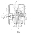
- the walking assembly of the invention which is composed here of a bottle 1 of very small size, typically of a height of less than 30 cm, for high pressure compressed gas, in particular oxygen, medical grade, on which is mounted the integrated pressure regulator valve assembly 2 of the invention comprising an internal filter 3 for protecting the entire valve, a residual pressure valve 4, an accessible gas charging plug or inlet 5 by a filling connector 6 through a protective cowling 7 to protect the valve-regulator assembly 2 against shocks, a pressure gauge 8 to view the pressure available in the bottle, a valve 9 for isolating the bottle whose operation is detailed below, detent means comprising a first expansion stage 10 on the Figure 2 equipped with a safety valve 11 and a second expansion stage 12.
- Said first 10 and second 12 stages of expansion comprise conventional expansion members, such as valves, valve seats, spring means ..., allowing the gas to be relieved from its high pressure, that is to say say the pressure of the gas at the bottle outlet, for example 200 bar, to its low pressure, that is to say its operating pressure, for example 1 bar, after passing through an intermediate pressure.
- conventional expansion members such as valves, valve seats, spring means ...
- the valve-expansion valve assembly also comprises a specific output interface 13 for connecting the demand valve 14, said connection allowing the unlocking of the rotary member 18 of the valve 9, that is to say that the The valve 9 can not be opened without first connecting the valve 14 to it, as explained below.
- the oxygen therapy bezel 15 is connected to the outlet of the valve 14 on demand so as to supply the patient with oxygen whose pressure has been reduced in the two stages 10, 12 of relaxation. Indeed, such a dual-pressure reduction system 10, 12 ensures a constant flow rate regardless of the filling level of the bottle.
- valve-expander assembly of the invention comprises an optional means operable by the user to temporarily increase the oxygen flow rate subsequent to its activation, for example a button 12b actuated by digital pressure and to compress the expansion spring of the piston of the second stage 12 of expansion to temporarily increase the pressure relaxed during the support time, in order to obtain an increase in oxygen flow rate adapted to the additional efforts of the patient.
- an optional means operable by the user to temporarily increase the oxygen flow rate subsequent to its activation for example a button 12b actuated by digital pressure and to compress the expansion spring of the piston of the second stage 12 of expansion to temporarily increase the pressure relaxed during the support time, in order to obtain an increase in oxygen flow rate adapted to the additional efforts of the patient.
- the valve further comprises a safety valve 11 for evacuating any overpressure in the event of failure of the first expansion valve of the first expansion stage.
- valve regulator assembly 2 is provided with a specific output interface carrying the locking valve 9 controlling the gas inlet and the gas outlet, said outlet interface being, furthermore, intended to receive a device 14 using the oxygen at reduced pressure delivered by the assembly 2, such as a flow meter, a valve on demand or an opening tool necessary to purge the gas from the bottle ,.
- a device 14 using the oxygen at reduced pressure delivered by the assembly 2 such as a flow meter, a valve on demand or an opening tool necessary to purge the gas from the bottle ,.
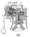
- the input interface of the apparatus 14 using the gas cooperates with the output interface of the valve-regulator assembly 2 so as to releasing the rotation of the rotary actuating member 18, such as a ring or flywheel, of the locking valve 9, as illustrated in FIGS. Figures 2 to 4 .
- the opening of the locking valve 9, that is to say the release of the gas can only be done once the apparatus of use 14 connected to the pressure-reducing valve 2.
- the utilization apparatus 14 comprises an input interface, acting as a connection socket, complementary to the specific output interface of the regulator valve 2, cooperating with each other, so as not to release the gas only when they are connected to one another, thanks to the presence of a locking valve 9 whose 18 maneuvering member is operable only after adequate connection of these parts one to the other.
- the user selects a full bottle 1 by checking the indication of the pressure gauge 8, removes the protective film which protects the output interface of the regulator valve assembly 2 intended to receive the input interface of the valve on demand 14.
- connection interface of the demand valve 14 into the central orifice of the assembly 13 provided with the locking valve 9, which releases the operating member 18 of the locking valve 9 and then allows the release of the gas.
- the unlocking of the rotation of the operating member 18 is obtained by the action in repulsion of one or more pins, lugs or the like 14a carried by the demand valve 14 on one or more pins 17, balls or similar blocking, housed in the body of the valve-expansion valve and acting on the control ring 18 of the locking valve 9.
- each pin 17 being movable in its housing 17b partially projecting from said housing 17b under the effect of an elastic thrust exerted on it a spring means 17a located between said pin 17 and the bottom of the housing 17b where is inserted the pin 17 as schematized on the figure 2 .
- each pin 17 protruding from the housing 17b is housed in a recess or housing 28, adapted dimensioning, arranged in the actuating member 18, which blocks the rotation of said actuating member 18 forming a ring around the tap 9.
- the recesses or recesses 28 are holes or orifices which pass through the entire wall of the actuating ring 18.
- Which ring 18 thus released can then be operated in rotation by the operator to its limited open position by a stop and this, in order to open the valve 9 and release the gas, the drive of the valve 9 being made of coupled with a rotation of the valve 14 about its axis. The whole is then ready to deliver gas.
- valve 14 As soon as the valve 14 is rotated to the "open tap” position, it can no longer be disconnected.
- the gas arrives in the first expansion valve consisting of a piston 10 and a valve 11 to be relaxed from its high pressure. to a lower pressure, called intermediate pressure or average pressure.
- the gas expanded at the intermediate pressure arrives on the second expansion valve consisting of a valve 12 and piston 12a where it is expanded from the mean pressure to low pressure, commonly called final pressure or operating pressure.
- the final pressure level can at any time be increased by the user with the support of a button 12b compressing a little more relaxation spring of the second relaxation stage.
- a system making it possible to temporarily increase the flow rate by simply pressing a button 12a is an interesting optional feature because this increase in flow rate can be controlled directly by the patient himself when he feels the need, for example when he makes a greater effort, including climbing a hill or a staircase.
- the final pressure obtained communicates through the internal gas passage to a housing 13 opening at the outlet port carried by the outlet interface, which housing 13 is provided to receive a portion of the valve 14 or any other device to be connected to it.
- valve 14 oriented in the valve through the recesses 113a makes it possible to push the pins 17 back on elastic means 17a thanks to two pins 14a integral with the input interface of the valve 14, which releases the rotation of the ring 18, the latter then being angularly connected to the valve 14.
- the rotation of the valve 14 therefore drives the ring 18, the ramps 18a, 18b act on the slide 9 which moves transversely and allows the opening or closing of the valve in the direction of rotation of the valve.
- the outlet of the valve 14 is connected to an oxygen therapy bezel 15 and when the patient inhales, the demand valve opens and gives the prescribed flow that has been defined by a nozzle in the valve during its manufacture.
- a double action rupture disc inside the body of the expansion valve assembly 2 is also preferably incorporated a double action rupture disc, as described in the document FR 0211318 or the document US Patent 4,706,698 intended to overcome any untimely increase in pressure due to an intense source of heat, as well as a residual pressure valve guaranteeing a minimum pressure of emptying the bottle, thus avoiding, on the one hand, any retro-pollution by impurities at the end of use, when the bottle is empty or almost and a second rinse when filling the bottle with a new charge of gas.
- the whole of the invention is packaged and ready for use, either individually or as a pack of several bottles, and is preferably covered with a protective film 16 avoiding it being soiled during transport, for example the standardized color of the gas contained in the bottle 1, and including all the legal indications on the definition of said gas.
- the nasal breathing goggles and the demand valve 14 are held by the patient user who never separates from them because the equipment is suitable for a flow rate in accordance with the prescription provided by his physician.
- valve regulator / cylinder assembly of the invention after use of all the gas by the patient, is returned to the gas distributor for its filling gas. Once refilled, the valve regulator / bottle assembly is subjected to a filming and packing operation before being re-shipped.
Landscapes
- Engineering & Computer Science (AREA)
- General Engineering & Computer Science (AREA)
- Mechanical Engineering (AREA)
- Filling Or Discharging Of Gas Storage Vessels (AREA)
- Respiratory Apparatuses And Protective Means (AREA)
- Preventing Unauthorised Actuation Of Valves (AREA)
- Safety Valves (AREA)
- Magnetically Actuated Valves (AREA)
- Braking Arrangements (AREA)
- Fluid-Damping Devices (AREA)
Claims (12)
- Hahneinheit mit integriertem Entspannungsventil (2) mit einem Hauptkörper, der Folgendes aufweist:- eine interne Gaspassage, die es dem Gas erlaubt, zwischen einer Gaseinlassöffnung und einer Gasauslassöffnung zu zirkulieren,- Gasentspannungsmittel (10, 12), die auf der internen Gaspassage zwischen der Gaseinlassöffnung und der Gasauslassöffnung angeordnet sind, und- ein Absperrhahn (9), der dazu dient, das Freigeben des Gases zu steuern, und der ein Drehstellglied (18) aufweist, das vom Benutzer bedient werden kann,wobei die Einheit ferner Sperrmittel (17) aufweist, die auf das Drehstellglied (18) des Absperrhahns (9) derart einwirken, dass normalerweise jedes Drehen des Stellglieds (18) verhindert wird, wobei die Sperrmittel (17) einen oder mehrere bewegliche Teile aufweisen, die mit dem Stellglied (18) derart zusammenwirken, dass sie sein Drehen und das Freigeben des Gases verhindern,
dadurch gekennzeichnet, dass das Stellglied (18) auf einem Höcker (2a) des Körpers der Hahneinheit (2) zentriert ist, wobei der Höcker (2a) ferner die Gasauslassöffnung (13) trägt, die es erlaubt, das Gas zu verteilen, sowie Verbindungsmittel (19), die das Anschließen eines Geräts (14), das Gas verwendet, erlauben, versehen mit einer Einlassschnittstelle (13a), und ergänzenden Verbindungsmitteln (20), die mit den Verbindungsmitteln (19) des Höckers zusammenwirken können, wobei die Einlassschnittstelle (13a) des Gas verwendenden Geräts ausgebildet ist, um auf den mindestens einen beweglichen Teil (17) der Sperrmittel entgegenzuwirken, um das Drehen des Stellglieds (18) freizugeben, nachdem die Einlassschnittstelle (13a) des Gas verwendenden Geräts (14) an der Auslassschnittstelle der Hahneinheit (2) angeschlossen wurde. - Einheit nach Anspruch 1, dadurch gekennzeichnet, dass das Stellglied (18) ein Drehring ist.
- Einheit nach Anspruch 2, dadurch gekennzeichnet, dass mindestens ein beweglicher Teil (17) von elastischen Mitteln (17a) in Richtung des Rings (18) derart zurückgeschoben wird, dass er sich zumindest teilweise in mindestens eine Aussparung (28) fügt, die in dem Stellglied (18) eingerichtet und bemessen ist, um zumindest einen Teil des beweglichen Teils (17) derart aufzunehmen, dass das Drehen des Stellglieds (18) verhindert wird, wenn ein beweglicher Teil (17) zumindest teilweise in einer Aussparung (28) aufgenommen ist.
- Einheit nach Anspruch 3, dadurch gekennzeichnet, dass das oder die elastischen Mittel (17a) Federn sind.
- Einheit nach einem der Ansprüche 1 bis 4, dadurch gekennzeichnet, dass der oder die beweglichen Teile (17) Klötze, Kugeln oder Ähnliches sind.
- Einheit nach einem der Ansprüche 1 bis 5, dadurch gekennzeichnet, dass die Gasentspannungsmittel (10, 12) eine erste Entspannungsstufe (10) und eine zweite Entspannungsstufe (12) aufweisen, die auf der internen Gaspassage eingerichtet sind, wobei die zweite Entspannungsstufe (12) stromabwärts der ersten Entspannungsstufe (10) liegt.
- Einheit nach einem der Ansprüche 1 bis 6, dadurch gekennzeichnet, dass sie ferner Folgendes aufweist:- ein Restdruckventil (4),- einen Druckmesser (8), der das Anzeigen des in der Flasche verfügbaren Drucks erlaubt,- einen Füllanschluss (5),- ein Filter (3), und/oder- ein Sicherheitsventil (11), das es erlaubt, jeden eventuellen Überdruck bei einem Versagen oder Bruch des ersten Entspannungsventils der ersten Entspannungsstufe (10) abzulassen.
- Einheit nach einem der Ansprüche 1 bis 7, dadurch gekennzeichnet, dass sie ferner ein Sofortbetätigungsmittel (12b) aufweist, das von dem Bediener betätigt werden kann, das auf die Entspannungsmittel der zweiten Entspannungsstufe (12) derart einwirkt, dass der entspannte Druck und der gelieferte Gasdurchsatz während der Zeit des Betätigens des Mittels (12) durch den Bediener sofort erhöht werden, wobei das Sofortbetätigungsmittel vorzugsweise ein Knopf (12b) ist, der die Entspannungsfeder des Kolbens der zweiten Entspannungsstufe (12) zusammendrückt.
- Tragbare Gehausstattung, deren Gewicht kleiner ist als 2 kg, die eine Druckgasflasche (1) aufweist, auf der eine Hahneinheit mit integriertem Entspannungsventil (2) nach einem der Ansprüche 1 bis 8 montiert ist, wobei die Gasflasche (1) vorzugsweise Sauerstoff enthält.
- Tragbare Ausstattung nach Anspruch 9, dadurch gekennzeichnet, dass sie ferner ein Gas verwendendes Gerät (14) aufweist, das über seine Einlassschnittstelle (13a) mit der Auslassschnittstelle (13) der Hahneinheit (2) verbunden ist, wobei das Gas verwendende Gerät (14) ergänzende Verbindungsmittel (20) aufweist, die mit den Verbindungsmitteln (19) der Auslassschnittstelle (13) der Hahneinheit (2) und mit den Sperrmitteln (17) zusammenwirken, die auf das Stellglied (18) derart einwirken, dass das Drehen des Stellglieds (18) und das Durchgehen des Gases der Hahneinheit (2) zu dem Gas verwendenden Gerät (14) gestattet wird.
- Tragbare Ausstattung nach Anspruch 10, dadurch gekennzeichnet, dass das Gas verwendende Gerät (14) aus den Ventilen auf Anfrage oder aus den Durchflussmessern ausgewählt ist.
- Tragbare Ausstattung nach Anspruch 9, dadurch gekennzeichnet, dass sie eine Schutzverkleidung aufweist, die derart angeordnet ist, dass sie die Hahneinheit mit integriertem Entspannungsventil schützt, wobei die Schutzverkleidung vorzugsweise auf der Hahneinheit (2) befestigt ist.
Applications Claiming Priority (2)
| Application Number | Priority Date | Filing Date | Title |
|---|---|---|---|
| FR0350495 | 2003-09-03 | ||
| FR0350495A FR2859289B1 (fr) | 2003-09-03 | 2003-09-03 | Robinet-detendeur integre avec moyens de blocage de l'organe d'actionnement |
Publications (2)
| Publication Number | Publication Date |
|---|---|
| EP1512895A1 EP1512895A1 (de) | 2005-03-09 |
| EP1512895B1 true EP1512895B1 (de) | 2009-03-11 |
Family
ID=38669577
Family Applications (1)
| Application Number | Title | Priority Date | Filing Date |
|---|---|---|---|
| EP20040300557 Expired - Lifetime EP1512895B1 (de) | 2003-09-03 | 2004-08-26 | Integriertes Entspannungsventil mit Vorrichtung zum Sperren des Stellgliedes |
Country Status (7)
| Country | Link |
|---|---|
| US (1) | US7287548B2 (de) |
| EP (1) | EP1512895B1 (de) |
| JP (1) | JP2005074231A (de) |
| AT (1) | ATE425398T1 (de) |
| AU (1) | AU2004208658A1 (de) |
| DE (1) | DE602004019857D1 (de) |
| FR (1) | FR2859289B1 (de) |
Families Citing this family (15)
| Publication number | Priority date | Publication date | Assignee | Title |
|---|---|---|---|---|
| US8011380B2 (en) * | 2009-10-01 | 2011-09-06 | Vision Tech International Llp | Single component two-stage regulator |
| FR2979718B1 (fr) * | 2011-09-01 | 2013-09-20 | Hampiaux S A S | Detendeur de gaz a un etage |
| CN105518374A (zh) * | 2013-09-12 | 2016-04-20 | 乔治洛德方法研究和开发液化空气有限公司 | 包括保护罩壳和带有用于指示向上位置中的压力或自主性的装置的气瓶的组件 |
| FR3018580B1 (fr) * | 2014-03-12 | 2018-11-02 | L'air Liquide, Societe Anonyme Pour L'etude Et L'exploitation Des Procedes Georges Claude | Bloc robinet pour recipient de gaz avec dispositif indicateur de pression ou d’autonomie en position haute |
| FR3025585B1 (fr) * | 2014-09-09 | 2016-09-09 | Air Liquide Medical Systems | Bloc robinet pour recipient de gaz a securite d'utilisation amelioree |
| DE102015005599A1 (de) * | 2015-04-29 | 2016-11-03 | Messer Gaspack Gmbh | Modulares Gasentnahmesystem für Druckgasflaschen |
| FR3050053B1 (fr) * | 2016-04-06 | 2018-05-04 | L'air Liquide, Societe Anonyme Pour L'etude Et L'exploitation Des Procedes Georges Claude | Procede de calcul de l'autonomie d'un ensemble de distribution de gaz |
| US10252094B1 (en) * | 2016-10-14 | 2019-04-09 | The United States Of America As Represented By The Secretary Of The Army | Fire extinguisher manifold with safety interlock cross-bolt |
| FR3075309B1 (fr) * | 2017-12-19 | 2020-01-10 | L'air Liquide, Societe Anonyme Pour L'etude Et L'exploitation Des Procedes Georges Claude | Robinet et bouteille de fluide sous pression |
| CN113833979B (zh) * | 2021-09-18 | 2023-10-20 | 西藏友氧健康科技有限公司 | 便携式液氧供氧装置 |
| FR3133320B1 (fr) | 2022-03-10 | 2024-08-23 | Air Liquide | Robinet pour récipient de gaz à détendeur intégré amélioré |
| KR102741995B1 (ko) * | 2022-07-14 | 2024-12-17 | 창조이앤이 주식회사 | 버튼식 스위치와 감압밸브를 구비한 범용식 산소 호흡기 |
| KR102544651B1 (ko) * | 2022-07-14 | 2023-06-20 | 씨아이앤티 주식회사 | 일체형 감압밸브를 구비한 충전식 산소 호흡기 |
| US12209683B2 (en) * | 2022-11-18 | 2025-01-28 | Forrest Neil Day | Locking device for a regulator and/or valve |
| FR3161256A1 (fr) | 2024-04-11 | 2025-10-17 | L'air Liquide, Societe Anonyme Pour L'etude Et L'exploitation Des Procedes Georges Claude | Bouteille d’oxygène légère adaptée au transport aérien ou terrestre |
Family Cites Families (7)
| Publication number | Priority date | Publication date | Assignee | Title |
|---|---|---|---|---|
| GB867642A (en) * | 1956-05-22 | 1961-05-10 | William Sugg & Company Ltd | Improvements in and relating to pipe fittings |
| FR1550319A (de) * | 1967-11-06 | 1968-12-20 | ||
| GB1425891A (en) * | 1973-03-02 | 1976-02-18 | Ewarts Ltd | Gas taps |
| DE2355950A1 (de) * | 1973-11-09 | 1975-05-15 | Koch & Mueller Armaturenfab | Gassteckhahn |
| US4928919A (en) * | 1988-10-21 | 1990-05-29 | Kabushiki Kaisha Neriki | Stop valve |
| FR2706016B1 (fr) * | 1993-06-03 | 1995-07-28 | France Prod Oxygenes Co | Chapeau de bouteille de gaz. |
| US5937895A (en) * | 1998-04-17 | 1999-08-17 | Uop Llc | Fail-safe delivery valve for pressurized tanks |
-
2003
- 2003-09-03 FR FR0350495A patent/FR2859289B1/fr not_active Expired - Fee Related
-
2004
- 2004-08-26 AT AT04300557T patent/ATE425398T1/de not_active IP Right Cessation
- 2004-08-26 EP EP20040300557 patent/EP1512895B1/de not_active Expired - Lifetime
- 2004-08-26 DE DE200460019857 patent/DE602004019857D1/de not_active Expired - Fee Related
- 2004-09-02 US US10/933,099 patent/US7287548B2/en not_active Expired - Fee Related
- 2004-09-02 AU AU2004208658A patent/AU2004208658A1/en not_active Abandoned
- 2004-09-02 JP JP2004255794A patent/JP2005074231A/ja active Pending
Also Published As
| Publication number | Publication date |
|---|---|
| US7287548B2 (en) | 2007-10-30 |
| JP2005074231A (ja) | 2005-03-24 |
| AU2004208658A1 (en) | 2005-03-17 |
| FR2859289A1 (fr) | 2005-03-04 |
| US20060042723A1 (en) | 2006-03-02 |
| DE602004019857D1 (de) | 2009-04-23 |
| FR2859289B1 (fr) | 2006-02-17 |
| EP1512895A1 (de) | 2005-03-09 |
| ATE425398T1 (de) | 2009-03-15 |
Similar Documents
| Publication | Publication Date | Title |
|---|---|---|
| EP1512895B1 (de) | Integriertes Entspannungsventil mit Vorrichtung zum Sperren des Stellgliedes | |
| EP1943455B1 (de) | Anordnung mit einem tank zur lagerung eines druckgases und steuerungsvorrichtung zur füllung des tanks mit gas oder zur extraktion von gas aus diesem | |
| WO2003019056A1 (fr) | Robinet de controle du debit d'un fluide equipe d'un levier a plusieurs positions stables | |
| CA2637319A1 (fr) | Dispositif de commande du remplissage et/ou du soutirage de fluide et reservoir comportant un tel dispositif | |
| EP0581947B1 (de) | Behälter zum spenden von flüssigkeiten | |
| EP3220985A1 (de) | Vorrichtung zur verteilung eines flüssigprodukts durch inhalation | |
| CA2751127A1 (fr) | Combinaison de protection d'une personne et ensemble correspondant | |
| EP3578871B1 (de) | Vorrichtung zur versorgung mit fluid unter druck | |
| EP4227575B1 (de) | Tragbare notsauerstoffabgabeanordnung mit sauerstoffspeicherpatrone | |
| EP3114390A1 (de) | Gasverteilungshahn mit fester und mobiler kappe | |
| FR2508799A1 (fr) | Appareil de respiration artificielle destine a etre utilise dans des chambres sous pression | |
| EP4227574B1 (de) | Tragbare notsauerstoffabgabeanordnung mit flusskontrollventilen | |
| FR3074051B1 (fr) | Dispositif de distribution de produit fluide synchronise avec l'inhalation | |
| FR2650763A1 (fr) | Vaporisateur portatif rechargeable pour liquides | |
| JP2521543Y2 (ja) | 吸入ガス供給用定流量弁 | |
| BE538094A (de) | ||
| FR3066804A1 (fr) | Robinet a detenteur integre et vanne de fermeture manuelle pour recipient de gaz | |
| WO1985004634A1 (fr) | Dispositif individuel de sauvetage | |
| JP2003269697A (ja) | 高圧ガス容器用開閉弁 | |
| EP1342140A2 (de) | Erweiterbare ventilbaugruppe für fluide mit voreingestelltem und nicht vom benutzer modifizierbarem festem druck | |
| FR3113714A1 (fr) | Robinet de distribution de gaz en laiton à raccords de sortie nickelés | |
| FR3155823A1 (fr) | Dispositif d’affalage hydraulique à commande manuelle pour engin de levage | |
| EP1241551A1 (de) | Gasdruckreduzierventil mit entkuppelbarem Druckverstellknopf | |
| FR2762378A1 (fr) | Organe de remplissage d'une bouteille portable de gaz et dispositif de rechargement en liquide et en gaz d'une installation portative de distribution d'un liquide sous pression | |
| FR2761609A1 (fr) | Appareil respiratoire de secours |
Legal Events
| Date | Code | Title | Description |
|---|---|---|---|
| PUAI | Public reference made under article 153(3) epc to a published international application that has entered the european phase |
Free format text: ORIGINAL CODE: 0009012 |
|
| AK | Designated contracting states |
Kind code of ref document: A1 Designated state(s): AT BE BG CH CY CZ DE DK EE ES FI FR GB GR HU IE IT LI LU MC NL PL PT RO SE SI SK TR |
|
| AX | Request for extension of the european patent |
Extension state: AL HR LT LV MK |
|
| 17P | Request for examination filed |
Effective date: 20050909 |
|
| AKX | Designation fees paid |
Designated state(s): AT BE BG CH CY CZ DE DK EE ES FI FR GB GR HU IE IT LI LU MC NL PL PT RO SE SI SK TR |
|
| 17Q | First examination report despatched |
Effective date: 20060217 |
|
| GRAP | Despatch of communication of intention to grant a patent |
Free format text: ORIGINAL CODE: EPIDOSNIGR1 |
|
| GRAS | Grant fee paid |
Free format text: ORIGINAL CODE: EPIDOSNIGR3 |
|
| GRAA | (expected) grant |
Free format text: ORIGINAL CODE: 0009210 |
|
| AK | Designated contracting states |
Kind code of ref document: B1 Designated state(s): AT BE BG CH CY CZ DE DK EE ES FI FR GB GR HU IE IT LI LU MC NL PL PT RO SE SI SK TR |
|
| REG | Reference to a national code |
Ref country code: GB Ref legal event code: FG4D Free format text: NOT ENGLISH |
|
| REG | Reference to a national code |
Ref country code: CH Ref legal event code: EP |
|
| REG | Reference to a national code |
Ref country code: IE Ref legal event code: FG4D Free format text: LANGUAGE OF EP DOCUMENT: FRENCH |
|
| REF | Corresponds to: |
Ref document number: 602004019857 Country of ref document: DE Date of ref document: 20090423 Kind code of ref document: P |
|
| PG25 | Lapsed in a contracting state [announced via postgrant information from national office to epo] |
Ref country code: SI Free format text: LAPSE BECAUSE OF FAILURE TO SUBMIT A TRANSLATION OF THE DESCRIPTION OR TO PAY THE FEE WITHIN THE PRESCRIBED TIME-LIMIT Effective date: 20090311 Ref country code: FI Free format text: LAPSE BECAUSE OF FAILURE TO SUBMIT A TRANSLATION OF THE DESCRIPTION OR TO PAY THE FEE WITHIN THE PRESCRIBED TIME-LIMIT Effective date: 20090311 Ref country code: NL Free format text: LAPSE BECAUSE OF FAILURE TO SUBMIT A TRANSLATION OF THE DESCRIPTION OR TO PAY THE FEE WITHIN THE PRESCRIBED TIME-LIMIT Effective date: 20090311 |
|
| NLV1 | Nl: lapsed or annulled due to failure to fulfill the requirements of art. 29p and 29m of the patents act | ||
| PG25 | Lapsed in a contracting state [announced via postgrant information from national office to epo] |
Ref country code: PL Free format text: LAPSE BECAUSE OF FAILURE TO SUBMIT A TRANSLATION OF THE DESCRIPTION OR TO PAY THE FEE WITHIN THE PRESCRIBED TIME-LIMIT Effective date: 20090311 Ref country code: SE Free format text: LAPSE BECAUSE OF FAILURE TO SUBMIT A TRANSLATION OF THE DESCRIPTION OR TO PAY THE FEE WITHIN THE PRESCRIBED TIME-LIMIT Effective date: 20090611 Ref country code: AT Free format text: LAPSE BECAUSE OF FAILURE TO SUBMIT A TRANSLATION OF THE DESCRIPTION OR TO PAY THE FEE WITHIN THE PRESCRIBED TIME-LIMIT Effective date: 20090311 |
|
| REG | Reference to a national code |
Ref country code: IE Ref legal event code: FD4D |
|
| PG25 | Lapsed in a contracting state [announced via postgrant information from national office to epo] |
Ref country code: EE Free format text: LAPSE BECAUSE OF FAILURE TO SUBMIT A TRANSLATION OF THE DESCRIPTION OR TO PAY THE FEE WITHIN THE PRESCRIBED TIME-LIMIT Effective date: 20090311 Ref country code: PT Free format text: LAPSE BECAUSE OF FAILURE TO SUBMIT A TRANSLATION OF THE DESCRIPTION OR TO PAY THE FEE WITHIN THE PRESCRIBED TIME-LIMIT Effective date: 20090824 Ref country code: ES Free format text: LAPSE BECAUSE OF FAILURE TO SUBMIT A TRANSLATION OF THE DESCRIPTION OR TO PAY THE FEE WITHIN THE PRESCRIBED TIME-LIMIT Effective date: 20090622 Ref country code: CZ Free format text: LAPSE BECAUSE OF FAILURE TO SUBMIT A TRANSLATION OF THE DESCRIPTION OR TO PAY THE FEE WITHIN THE PRESCRIBED TIME-LIMIT Effective date: 20090311 Ref country code: IE Free format text: LAPSE BECAUSE OF FAILURE TO SUBMIT A TRANSLATION OF THE DESCRIPTION OR TO PAY THE FEE WITHIN THE PRESCRIBED TIME-LIMIT Effective date: 20090311 |
|
| PG25 | Lapsed in a contracting state [announced via postgrant information from national office to epo] |
Ref country code: RO Free format text: LAPSE BECAUSE OF FAILURE TO SUBMIT A TRANSLATION OF THE DESCRIPTION OR TO PAY THE FEE WITHIN THE PRESCRIBED TIME-LIMIT Effective date: 20090311 Ref country code: SK Free format text: LAPSE BECAUSE OF FAILURE TO SUBMIT A TRANSLATION OF THE DESCRIPTION OR TO PAY THE FEE WITHIN THE PRESCRIBED TIME-LIMIT Effective date: 20090311 |
|
| RAP2 | Party data changed (patent owner data changed or rights of a patent transferred) |
Owner name: AIR LIQUIDE MEDICAL SYSTEMS |
|
| PLBE | No opposition filed within time limit |
Free format text: ORIGINAL CODE: 0009261 |
|
| STAA | Information on the status of an ep patent application or granted ep patent |
Free format text: STATUS: NO OPPOSITION FILED WITHIN TIME LIMIT |
|
| PG25 | Lapsed in a contracting state [announced via postgrant information from national office to epo] |
Ref country code: DK Free format text: LAPSE BECAUSE OF FAILURE TO SUBMIT A TRANSLATION OF THE DESCRIPTION OR TO PAY THE FEE WITHIN THE PRESCRIBED TIME-LIMIT Effective date: 20090311 Ref country code: BG Free format text: LAPSE BECAUSE OF FAILURE TO SUBMIT A TRANSLATION OF THE DESCRIPTION OR TO PAY THE FEE WITHIN THE PRESCRIBED TIME-LIMIT Effective date: 20090611 |
|
| 26N | No opposition filed |
Effective date: 20091214 |
|
| REG | Reference to a national code |
Ref country code: FR Ref legal event code: CD |
|
| BERE | Be: lapsed |
Owner name: TAEMA Effective date: 20090831 |
|
| PG25 | Lapsed in a contracting state [announced via postgrant information from national office to epo] |
Ref country code: MC Free format text: LAPSE BECAUSE OF NON-PAYMENT OF DUE FEES Effective date: 20090831 |
|
| REG | Reference to a national code |
Ref country code: CH Ref legal event code: PL |
|
| GBPC | Gb: european patent ceased through non-payment of renewal fee |
Effective date: 20090826 |
|
| PG25 | Lapsed in a contracting state [announced via postgrant information from national office to epo] |
Ref country code: CH Free format text: LAPSE BECAUSE OF NON-PAYMENT OF DUE FEES Effective date: 20090831 Ref country code: LI Free format text: LAPSE BECAUSE OF NON-PAYMENT OF DUE FEES Effective date: 20090831 |
|
| PG25 | Lapsed in a contracting state [announced via postgrant information from national office to epo] |
Ref country code: BE Free format text: LAPSE BECAUSE OF NON-PAYMENT OF DUE FEES Effective date: 20090831 |
|
| PG25 | Lapsed in a contracting state [announced via postgrant information from national office to epo] |
Ref country code: DE Free format text: LAPSE BECAUSE OF NON-PAYMENT OF DUE FEES Effective date: 20100302 |
|
| PG25 | Lapsed in a contracting state [announced via postgrant information from national office to epo] |
Ref country code: GR Free format text: LAPSE BECAUSE OF FAILURE TO SUBMIT A TRANSLATION OF THE DESCRIPTION OR TO PAY THE FEE WITHIN THE PRESCRIBED TIME-LIMIT Effective date: 20090612 |
|
| PG25 | Lapsed in a contracting state [announced via postgrant information from national office to epo] |
Ref country code: GB Free format text: LAPSE BECAUSE OF NON-PAYMENT OF DUE FEES Effective date: 20090826 |
|
| PG25 | Lapsed in a contracting state [announced via postgrant information from national office to epo] |
Ref country code: IT Free format text: LAPSE BECAUSE OF FAILURE TO SUBMIT A TRANSLATION OF THE DESCRIPTION OR TO PAY THE FEE WITHIN THE PRESCRIBED TIME-LIMIT Effective date: 20090311 |
|
| PG25 | Lapsed in a contracting state [announced via postgrant information from national office to epo] |
Ref country code: LU Free format text: LAPSE BECAUSE OF NON-PAYMENT OF DUE FEES Effective date: 20090826 |
|
| PG25 | Lapsed in a contracting state [announced via postgrant information from national office to epo] |
Ref country code: HU Free format text: LAPSE BECAUSE OF FAILURE TO SUBMIT A TRANSLATION OF THE DESCRIPTION OR TO PAY THE FEE WITHIN THE PRESCRIBED TIME-LIMIT Effective date: 20090912 |
|
| PG25 | Lapsed in a contracting state [announced via postgrant information from national office to epo] |
Ref country code: TR Free format text: LAPSE BECAUSE OF FAILURE TO SUBMIT A TRANSLATION OF THE DESCRIPTION OR TO PAY THE FEE WITHIN THE PRESCRIBED TIME-LIMIT Effective date: 20090311 |
|
| PG25 | Lapsed in a contracting state [announced via postgrant information from national office to epo] |
Ref country code: CY Free format text: LAPSE BECAUSE OF FAILURE TO SUBMIT A TRANSLATION OF THE DESCRIPTION OR TO PAY THE FEE WITHIN THE PRESCRIBED TIME-LIMIT Effective date: 20090311 |
|
| REG | Reference to a national code |
Ref country code: FR Ref legal event code: PLFP Year of fee payment: 13 |
|
| REG | Reference to a national code |
Ref country code: FR Ref legal event code: PLFP Year of fee payment: 14 |
|
| REG | Reference to a national code |
Ref country code: FR Ref legal event code: PLFP Year of fee payment: 15 |
|
| PGFP | Annual fee paid to national office [announced via postgrant information from national office to epo] |
Ref country code: FR Payment date: 20190822 Year of fee payment: 16 |
|
| PG25 | Lapsed in a contracting state [announced via postgrant information from national office to epo] |
Ref country code: FR Free format text: LAPSE BECAUSE OF NON-PAYMENT OF DUE FEES Effective date: 20200831 |