EP1512831B1 - Feed table pivot pin constraining device - Google Patents
Feed table pivot pin constraining device Download PDFInfo
- Publication number
- EP1512831B1 EP1512831B1 EP04253235A EP04253235A EP1512831B1 EP 1512831 B1 EP1512831 B1 EP 1512831B1 EP 04253235 A EP04253235 A EP 04253235A EP 04253235 A EP04253235 A EP 04253235A EP 1512831 B1 EP1512831 B1 EP 1512831B1
- Authority
- EP
- European Patent Office
- Prior art keywords
- constraint
- pair
- female
- male
- members
- Prior art date
- Legal status (The legal status is an assumption and is not a legal conclusion. Google has not performed a legal analysis and makes no representation as to the accuracy of the status listed.)
- Expired - Lifetime
Links
- 210000005069 ears Anatomy 0.000 claims abstract description 34
- 230000000452 restraining effect Effects 0.000 claims abstract description 34
- 238000000926 separation method Methods 0.000 claims abstract description 15
- 230000000717 retained effect Effects 0.000 claims abstract description 4
- 238000003780 insertion Methods 0.000 claims description 19
- 230000037431 insertion Effects 0.000 claims description 19
- 238000000034 method Methods 0.000 claims description 8
- 230000003993 interaction Effects 0.000 claims description 4
- 229910000831 Steel Inorganic materials 0.000 claims description 2
- 239000010959 steel Substances 0.000 claims description 2
- 238000005553 drilling Methods 0.000 description 7
- 239000011435 rock Substances 0.000 description 6
- 239000000463 material Substances 0.000 description 2
- 239000007769 metal material Substances 0.000 description 1
- JTJMJGYZQZDUJJ-UHFFFAOYSA-N phencyclidine Chemical compound C1CCCCN1C1(C=2C=CC=CC=2)CCCCC1 JTJMJGYZQZDUJJ-UHFFFAOYSA-N 0.000 description 1
- 238000003466 welding Methods 0.000 description 1
Images


Classifications
-
- E—FIXED CONSTRUCTIONS
- E21—EARTH OR ROCK DRILLING; MINING
- E21B—EARTH OR ROCK DRILLING; OBTAINING OIL, GAS, WATER, SOLUBLE OR MELTABLE MATERIALS OR A SLURRY OF MINERALS FROM WELLS
- E21B3/00—Rotary drilling
- E21B3/02—Surface drives for rotary drilling
- E21B3/04—Rotary tables
- E21B3/045—Rotary tables movably mounted on the drilling structure or platform
-
- E—FIXED CONSTRUCTIONS
- E21—EARTH OR ROCK DRILLING; MINING
- E21B—EARTH OR ROCK DRILLING; OBTAINING OIL, GAS, WATER, SOLUBLE OR MELTABLE MATERIALS OR A SLURRY OF MINERALS FROM WELLS
- E21B7/00—Special methods or apparatus for drilling
- E21B7/02—Drilling rigs characterised by means for land transport with their own drive, e.g. skid mounting or wheel mounting
- E21B7/021—With a rotary table, i.e. a fixed rotary drive for a relatively advancing tool
Definitions
- the present invention generally relates to a mobile track drill. More specifically, the present invention relates to a mechanical device that restricts the relative movement between the feed table and the positioning elements of drilling equipment upon mechanical failure.
- a drill track is used to guide the movement of a drill along a longitudinal axis.
- the drill track in turn, is mounted to a feed table that serves as the point of connection to the articulated drilling boom of the movable track drill.
- the feed table includes a pivot pin that is received and retained within a positioner block mounted to the drilling boom.
- the positioner block in turn, is coupled to a hydraulic cylinder to control the position of the drill track to orient the drill track in the desired direction.
- the pivot pin contained on the feed table allows the feed table and the attached drill track to rotate relative to the positioner block to further control the position of the drill track as desired.
- the feed table is manufactured such that the pivot pin is inserted into the positioner block and a retaining cap is attached to the pivot pin by a series of bolts to retain the pivot pin within the positioner block.
- the axial alignment and integrity of the feed table/positioner block joint is assured only by the material integrity of the pivot pin, the retaining cap and the connecting bolts.
- US Patent 2,908,482 discloses a rock drill having a pneumatic feed leg that is pivotally attached to a pair of support arms of the drilling tool, via a yoke.
- the yoke includes yoke arms that carry bearing sleeves in which studs or pin-like trunnions are secured, as by welding, to the parallel support arms.
- the studs serve as pivot elements and have retaining nuts threaded thereon to hold the parts in position.
- By adjusting the nuts the frictional binding contract between the yoke arms and the supporting arms may be varied, thereby to vary frictionally the relative pivotal movement between the tool and the feed leg. In the event of a failure of the studs or restraining nuts such that the support arms are separated from the yoke, the drilling too) becomes unrestrained.
- US Patent 3,322,378 which is considered as the closest prior art, discloses a tripod drill support that implements a gimbal member to permit bi-axial rotation of the drill.
- the gimbal member comprises cylindrical end portions and an intermediate portion separating and rigidly securing the cylindrical end portions for a purpose of rotatably receiving an elongated cylindrical pin, which is captively secured in a mounting element associated with a drill guide frame. In the event of failure of the securing arms, the pin is free to slide out of the intermediate portion so that the drill becomes separated from the support.
- the present invention is a restraining arrangement that limits the possible - separation between the drill boom and drill assembly of a mobile track drill.
- the restraining arrangement acts to prevent the unrestrained movement of the drill assembly.
- the upper rim of the bushing includes a pair of extended ears that are spaced from each other along the outer circumference of the upper rim.
- the restraining arrangement includes a second constraint device that is secured to the feed table of the drilling assembly.
- the feed table in turn, is securely connected to the drill track and provides the point of rotatable connection between the drill track and the positioner block.
- the feed table includes a pivot pin that extends from the feed table and is received within the positioner block.
- the pivot pin is received within the open interior of the bushing secured within the positioner block.
- the second constraint device includes a pair of female constraint members that are mounted to the lower wall of the feed table.
- the female constraint members are spaced from the pivot pin and each include a recessed groove.
- the recessed groove formed on each of the female constraint members is sized to receive the extended ears formed on the bushing such that the ears of the bushing are freely rotatable within the recessed grooves.
- the female constraining members are spaced from each other to define a pair of insertion gaps.
- the recessed groove formed in each of the female constraint members is interrupted along the insertion gap.
- the insertion gap allows the upper rim, and more specifically the extended ears, of the bushing to be inserted within the female constraint members.
- the second constraint device further includes a pair of retaining caps that are mountable between the female constraint members.
- the retaining caps are mountable to the female constraint members such that the retainer caps extend across the insertion gaps to secure the bushing between the pair of female constraint members.
- Each of the retaining caps includes a recessed groove similar to the recessed groove formed in the female constraint members, such that when the retaining caps are mounted to the female constraint members, the recessed groove is continuous around the pivot pin. The continuous recessed groove allows the extended ears of the bushing to rotate freely while preventing separation between the bushing and the female constraint members.
- the restraining arrangement of the present invention thus allows unrestricted rotation of the feed table relative to the positioner block while limiting the separation between the feed table and the positioner block should a structural failure occur in either the retaining cap, the pivot pin or the connectors used to secure the pivot pin within the positioner block.
- the restraining arrangement of the present invention thus provides an additional level of security to restrict the uncontrolled movement of the drilling assembly relative to the drill boom of the track drill upon failure of structural components within the track drill.
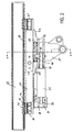
- a mobile track drill 10 that incorporates the features of the present invention.
- the mobile track drill 10 is a HYDRA-TRAC ® hydraulic track drill available from Reedrill of Sherman, Texas.
- the mobile track drill 10 includes an engine 12 supported by a pair of track drives 14.
- the track drives 14 are entrained about a series of wheels such that the mobile track drill 10 can be moved to various locations for use.
- the mobile track drill 10 includes a multi-section drill boom 16 that is used to support and position a drill assembly 18.
- the orientation of the drill assembly 18 can be controlled through various hydraulic cylinders as will be discussed in greater detail below.
- the drill boom 16 includes a first section 20 whose angular position is controlled by a first drive cylinder 22.
- the first section 20 is rotatably connected to a second section 24 about a pivot point 26.
- the movement of the second section 24 relative to the first section 20 is controlled by a second hydraulic drive cylinder 28.
- the extension and retraction of the second drive cylinder 28 controls the rotation of the second section 24 relative to the first section 20.
- the positioner block 30 is rotatable about a pivot point 32 and such rotation is controlled by a third drive cylinder 34.
- the extension and retraction of the third drive cylinder 34 controls the orientation of the positioner block 30, as can be understood.
- the feed table 36 as will be described in greater detail below, is pivotable within the positioner block 30 such that the feed table 36 can rotate relative to the positioner block 30.
- the feed table 36 is securely mounted to a drill track 38 that extends from a first end 40 to a second end 42.
- the drill track 38 has a length of approximately 9,1 m (thirty feet), although other lengths are contemplated as being within the scope of the present invention.
- a rock drill 44 is movable along the length of the drill track 38 and includes a drill bit 46. As is conventional, the rock drill 44 rotates the drill bit 46 to drill a hole as the rock drill 44 moves downward along the longitudinal axis of the drill track 38.
- the operation of the mobile track drill 10 is conventional and thus will not be described in greater detail in the present application.
- FIG. 2 and 3 thereshown is the physical connection between the drill track 38, feed table 36 and positioner block 30, including the restraining arrangement of the present arrangement.
- the drill track 38 is shown in a shortened condition for illustrative purposes only. It should be understood that the drill track 38 has a length substantially longer than shown.
- the drill track 38 includes a lower lip 50 and an upper lip 51 formed on each of its opposite sides.
- the upper lip 51 serves as the point of attachment for the rock drill 44, shown in Fig. 1 , and allows the rock drill to move along the length of the drill track 38.
- the lower lip 50 serves as a secure point of attachment for the support beam 52 of the feed table 36.
- the support beam 52 has a generally rectangular cross-section that includes an upper, attachment wall 54, a pair of sidewalls 56 and a lower support wall 58.
- the support beam 52 includes a pair of mounting brackets 60 positioned at its first end 62 and a corresponding pair of mounting brackets 64 positioned near its second end 66. Each of the mounting brackets 60, 64 are preferably welded to the support beam 52.
- the support beam 52 is secured to the drill track 38 by a first pair of brackets 68 and a second pair of brackets 70.
- the brackets 68 and 70 interact with the brackets 60 and 64 to hold the support beam 52 in contact with the lower lip 50 of the drill track 38.
- a series of cap screws 72 pass through a wear pad 74 and a shim 76 to secure the support beam 52 to the drill track 38, as best shown in Fig. 2 .
- the feed table 36 includes a weldment 78 attached to the lower support wall 58 beneath its first end 62.
- the weldment 78 includes a pair of extending tabs 80 that receive a first end 82 of the rotational drive cylinder 84.
- the drive cylinder 84 includes a cylinder rod 86 having an end 88 that receives a pin 90.
- the second end 88 of the cylinder 84 is fixed between an upper plate 92 and a lower plate 94 of the positioner block 30. Specifically, the pin 90 passes through one set of the three sets of aligned holes 96 and 98.
- the three sets of aligned holes 96,98 can be used to adjust the stroke length of the cylinder 84 and control the degree of rotation of the feed table 36 relative to the positioner block 30.
- Pin 100 passes through the aligned holes 102 and 104 of the extending tabs 80 to hold the first end 82 between the extending tabs 80.
- the extension and retraction of the drive cylinder 84 controls the rotational movement of the feed table 36 relative to the positioner block 30, as will be described in much greater detail below.
- the feed table 36 includes a pivot pin 106 that extends downward beneath the support wall 58 of the support beam 52.
- the pivot pin 106 is generally cylindrical in shape and includes an expanded diameter shoulder portion 108. As can be seen in Figs. 3 and 4 , the pivot pin 106 extends through the support beam 52 such that the top surface 110 of the pivot pin 106 is generally flush with the upper attachment wall 54. The opposite, second end 112 of the pivot pin 106 protrudes beneath the lower support wall 58 approximately eight inches (20.3cm).
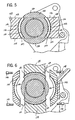
- a restraining arrangement 48 is positioned between the feed table 36 and the positioner block 30 to limit the possible separation of the feed table 36 from the positioner block 30.
- the restraining arrangement 48 includes a first constraint device 114 secured to the positioner block 30 and a second constraint device 116 secured to the feed table 36. The interaction between the first and second constraint devices allows for rotation of the feed table 36 relative to the positioner block 30 while preventing the movement of the feed table 36 away from the positioner block 30.
- the first constraint device 114 is a bushing 118 having a cylindrical lower body 120 and an upper rim 122.
- the cylindrical body 120 and the upper rim 122 are formed as a single component from a metallic material, such as high strenght steel.
- the cylindrical body 120 defines an open interior 124 having an inner diameter sized to receive the pivot pin 106 such that the pivot pin 106 is freely rotatable within the open interior 124.
- the cylindrical body 120 of the bushing 118 is received within a bore 126 formed in the positioner block 30.
- the bushing 118 is press fit into the bore 126 under pressure such that the bushing 118 is held in place by friction and is prevented from rotating relative to the positioner block 30.
- the upper rim 122 of the bushing 118 includes a pair of extended ears 128.
- the extended ears 128 protrude from the outer circumference of the upper rim 122 approximately 3/4 inches (1.9cm) and have a thickness of approximately one inch (2.5cm).
- Each of the ears 128 extend approximately 45 DEG along the outer circumference of the upper rim 122 and are thus separated by gaps of approximately 90 DEG.
- a retaining cap 130 is attached to the bottom end 112 of the pivot pin 106 by a series of connectors 132, as best shown in Fig. 4 .
- the retaining cap 130 is received within a central opening 134 of the positioner block 30.
- the central opening 134 includes an upper shoulder 136.
- the shoulder 136 prevents the retaining cap 130 from being pulled out of the positioner block 30, as can be clearly understood in Fig. 4 .
- the interaction between the retaining cap 130 and the pivot pin 106 thus prevents separation of the feed table 36 from the positioner block 30 while allowing the feed table 36 to rotate relative to the positioned block.
- the second constraining device 116 includes a pair of female constraint members 138 mounted to the lower support wall 58 of the support beam 52.
- Each of the female constraint members 138 defines an arcuate recessed groove 140.
- the recessed groove 140 has a height approximately equal to the thickness of the upper rim 122 of the bushing 118 such that the ears 128 of the bushing 118 can be received within the recessed grooves 140.
- the recessed grooves 140 have a curvature to correspond to the ear 128 such that the ears 128 can move along the length of the recessed grooves 140 as the feed table 36 rotates relative to the positioner block 30.
- each of the female constraint members 138 extends from a first face surface 142 to a second face surface 144.
- the recessed groove 140 is defined by a curved back wall 146 that is recessed from a curved outer wall 147 that defines an upper rim for the recessed groove 140.
- the groove 140 also includes a curved lower wall (not shown) similar to the outer wall 147 that defines a lower rim for the recessed groove 140.
- the curved back walls 146 of the opposed female constraint members 138 are spaced from each other by approximately the diameter of the upper rim 122 of the bushing 118 between the extending ears 128.
- the female constraint members 138 are spaced from each other to define a pair of insertion gaps 148 as shown in Fig. 3 .
- the feed table including the pair of female constraint members 138, are rotated such that the female constraint members 138 are aligned with the portions 150 of the upper rim 122 between the pair of extending ears 128. In this position, the ears 128 are generally aligned with the insertion gaps extending between the pair of female constraint members 138.
- the feed table and the pair of female constraint members 138 are rotated 90° such that the ears 128 of the bushing are received within the recessed grooves 140 formed in the pair of female constraint members 138, as shown in Figs. 5 and 6 .
- the height of the recessed grooves 140 formed in the female constraint members 138 is generally equal to the thickness of the ears 128 such that the ears are movable within the recessed grooves 140.
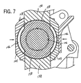
- the restraining arrangement 48 of the present invention further includes a pair of retainer caps 142 and 144. As illustrated in Fig. 6 , each of the retaining caps 142 and 144 includes a recessed groove 146 having the same depth and height as the recessed grooves 140 formed in each of the female constraint members 138.
- Each of the retainer caps 142 and 144 is attachable to both of the female constraint members 138 by a series of connectors 148.
- the connectors 148 are received within holes 150 formed in the female constraint members 138.
- Fig. 7 thereshown are the retainer caps 142 and 144 mounted to the pair of female constraint members 138. In this condition, the ears 128 are completely enclosed within a recessed groove such that the bushing is prevented from separating from the pair of female constraint members 138 attached to the feed table.
Landscapes
- Engineering & Computer Science (AREA)
- Geology (AREA)
- Mining & Mineral Resources (AREA)
- Life Sciences & Earth Sciences (AREA)
- General Life Sciences & Earth Sciences (AREA)
- Fluid Mechanics (AREA)
- Environmental & Geological Engineering (AREA)
- Physics & Mathematics (AREA)
- Geochemistry & Mineralogy (AREA)
- Mechanical Engineering (AREA)
- Earth Drilling (AREA)
- Drilling And Boring (AREA)
- Holding Or Fastening Of Disk On Rotational Shaft (AREA)
- Spinning Or Twisting Of Yarns (AREA)
- Feeding Of Workpieces (AREA)
Applications Claiming Priority (2)
| Application Number | Priority Date | Filing Date | Title |
|---|---|---|---|
| US657433 | 2003-09-08 | ||
| US10/657,433 US7100709B2 (en) | 2003-09-08 | 2003-09-08 | Feed table pivot pin constraining device |
Publications (2)
| Publication Number | Publication Date |
|---|---|
| EP1512831A1 EP1512831A1 (en) | 2005-03-09 |
| EP1512831B1 true EP1512831B1 (en) | 2010-06-30 |
Family
ID=34136724
Family Applications (1)
| Application Number | Title | Priority Date | Filing Date |
|---|---|---|---|
| EP04253235A Expired - Lifetime EP1512831B1 (en) | 2003-09-08 | 2004-05-29 | Feed table pivot pin constraining device |
Country Status (7)
| Country | Link |
|---|---|
| US (1) | US7100709B2 (pt) |
| EP (1) | EP1512831B1 (pt) |
| JP (1) | JP4486436B2 (pt) |
| AT (1) | ATE472667T1 (pt) |
| AU (1) | AU2004202119B2 (pt) |
| BR (1) | BRPI0403672A (pt) |
| DE (1) | DE602004027873D1 (pt) |
Families Citing this family (11)
| Publication number | Priority date | Publication date | Assignee | Title |
|---|---|---|---|---|
| US7100709B2 (en) * | 2003-09-08 | 2006-09-05 | Metso Minerals Industries, Inc. | Feed table pivot pin constraining device |
| CA2538742C (en) * | 2005-03-08 | 2009-10-27 | Innovative Pile Driving Products, Llc | Pile driver |
| SE529604C2 (sv) * | 2006-02-10 | 2007-10-02 | Atlas Copco Rock Drills Ab | Anordning vid en teleskopmatare för bergborrning |
| DK2084332T3 (da) * | 2006-11-03 | 2012-05-07 | Jay Gunnarson | System til montering af en rambuk |
| US8439566B2 (en) * | 2010-03-09 | 2013-05-14 | Caterpillar Global Mining Equipment Llc | Wear pad adjustment assembly |
| CN102373882A (zh) * | 2011-10-18 | 2012-03-14 | 沈阳北方重矿机械有限公司 | 分体自走式煤矿坑道钻机 |
| CN102418475B (zh) * | 2011-12-30 | 2013-11-06 | 中船重工中南装备有限责任公司 | 一种具有换钎装置的伸缩臂露天凿岩钻车 |
| CN102536141B (zh) * | 2012-01-20 | 2013-11-06 | 中船重工中南装备有限责任公司 | 一种凿岩钻车的自动换钎控制系统 |
| CN102691323B (zh) * | 2012-06-05 | 2014-08-27 | 重庆迪马工业有限责任公司 | 一种基于挖掘机平台的多功能工程机械 |
| US9834990B2 (en) * | 2012-12-28 | 2017-12-05 | Tesco Corporation | Bogey style torque bushing for top drive |
| CN103758453B (zh) * | 2014-01-23 | 2015-09-23 | 长沙精拓工程机械有限公司 | 智能化微型钻机 |
Family Cites Families (32)
| Publication number | Priority date | Publication date | Assignee | Title |
|---|---|---|---|---|
| US2123897A (en) * | 1935-06-18 | 1938-07-19 | Sullivan Machinery Co | Drilling apparatus |
| US2334312A (en) * | 1940-08-05 | 1943-11-16 | George E Failing Supply Compan | Drilling machine |
| US2815191A (en) * | 1950-05-10 | 1957-12-03 | Jeffrey Mfg Co | Apparatus for carrying a drilling mechanism along a desired path |
| US2799249A (en) * | 1950-07-06 | 1957-07-16 | Chicago Pneumatic Tool Co | Boom actuating motor and locking means |
| US2908482A (en) | 1952-07-16 | 1959-10-13 | Joy Mfg Co | Rock drill |
| US2792198A (en) * | 1953-03-30 | 1957-05-14 | Longyear E J Co | Portable drill rig |
| US3021099A (en) * | 1958-11-04 | 1962-02-13 | Chicago Pneumatic Tool Co | Universal hydraulic drill positioner |
| US3252527A (en) * | 1963-09-04 | 1966-05-24 | George E Failing Company | Rotary drilling rig and angle drive therefor |
| US3322378A (en) | 1965-01-13 | 1967-05-30 | Joy Mfg Co | Tripod drill support |
| GB1217077A (en) * | 1968-05-30 | 1970-12-23 | Atlas Copco Ab | Improvements in mobile drill rigs |
| US3664436A (en) * | 1970-05-15 | 1972-05-23 | Michael A Beagan Jr | Adjustable mounting for rock drills |
| NO127680B (pt) * | 1971-12-08 | 1973-07-30 | Anlegg & Maskin As | |
| US3896887A (en) * | 1973-12-26 | 1975-07-29 | Gardner Denver Co | Mounting for drill rig mast |
| US3965628A (en) * | 1974-04-05 | 1976-06-29 | Joy Manufacturing Company | Drill mast support assembly |
| US4099579A (en) * | 1977-02-09 | 1978-07-11 | Stormon Harry J | Drill mounting device for backhoe attachments |
| US4088289A (en) * | 1977-02-25 | 1978-05-09 | Gardner-Denver Company | Mast support arrangement for portable drill rig |
| DE3544086A1 (de) | 1985-12-13 | 1987-06-19 | Klemm Bohrtech | Erdbohrgeraet |
| FI80323C (fi) * | 1987-03-23 | 1990-05-10 | Tampella Oy Ab | Foerfarande och anordning foer styrning av bergborrning. |
| US4858700A (en) | 1987-06-26 | 1989-08-22 | Shafer James P | Articulated apparatus for positioning rock drills |
| FR2618483B1 (fr) | 1987-07-23 | 1989-12-15 | Sorenam | Machine de forage par rotation et par louvoiement |
| GB8805918D0 (en) | 1988-03-12 | 1988-04-13 | Boart Uk Ltd | Feed beam arrangement for rockdrill |
| FI83255C (fi) | 1988-07-12 | 1991-06-10 | Tampella Oy Ab | Matningsanordning foer bergborrmaskin. |
| US5226488A (en) | 1991-07-10 | 1993-07-13 | Bor-Mor Inc. | Truck mounted boring system |
| US5413186A (en) | 1994-05-13 | 1995-05-09 | Reedrill, Inc. | Reverse percussion device |
| FI97420C (fi) | 1995-03-17 | 1996-12-10 | Tamrock Oy | Sovitelma kallioporakoneen syöttöpalkissa |
| SE508941C2 (sv) | 1995-03-31 | 1998-11-16 | Atlas Copco Rocktech Ab | Borrningsanordning |
| US5941324A (en) | 1998-01-27 | 1999-08-24 | Schramm, Inc. | Drilling apparatus |
| US6357537B1 (en) | 2000-03-15 | 2002-03-19 | Vermeer Manufacturing Company | Directional drilling machine and method of directional drilling |
| CA2338823C (en) * | 2001-02-27 | 2004-07-06 | Hy-Tech Drilling Ltd. | Drilling apparatus |
| US6889779B2 (en) * | 2002-08-19 | 2005-05-10 | Skarlupka, Iv Joseph Henry | Auger/vehicle interface jig |
| US7100709B2 (en) * | 2003-09-08 | 2006-09-05 | Metso Minerals Industries, Inc. | Feed table pivot pin constraining device |
| EP1682396B1 (en) * | 2003-09-23 | 2014-03-12 | Dane Industries | Power assisted cart retriever with attenuated power output |
-
2003
- 2003-09-08 US US10/657,433 patent/US7100709B2/en not_active Expired - Lifetime
-
2004
- 2004-05-18 AU AU2004202119A patent/AU2004202119B2/en not_active Ceased
- 2004-05-29 AT AT04253235T patent/ATE472667T1/de not_active IP Right Cessation
- 2004-05-29 EP EP04253235A patent/EP1512831B1/en not_active Expired - Lifetime
- 2004-05-29 DE DE602004027873T patent/DE602004027873D1/de not_active Expired - Lifetime
- 2004-08-10 JP JP2004232963A patent/JP4486436B2/ja not_active Expired - Fee Related
- 2004-09-02 BR BR0403672-7A patent/BRPI0403672A/pt not_active Application Discontinuation
Also Published As
| Publication number | Publication date |
|---|---|
| US7100709B2 (en) | 2006-09-05 |
| ATE472667T1 (de) | 2010-07-15 |
| EP1512831A1 (en) | 2005-03-09 |
| DE602004027873D1 (de) | 2010-08-12 |
| BRPI0403672A (pt) | 2005-06-28 |
| JP4486436B2 (ja) | 2010-06-23 |
| JP2005083189A (ja) | 2005-03-31 |
| AU2004202119A1 (en) | 2005-03-24 |
| AU2004202119B2 (en) | 2006-11-02 |
| US20050051364A1 (en) | 2005-03-10 |
Similar Documents
| Publication | Publication Date | Title |
|---|---|---|
| EP1512831B1 (en) | Feed table pivot pin constraining device | |
| US5337847A (en) | Four-way levelling mechanism for off-road vehicle | |
| US6698529B2 (en) | Translating turret rock bolter | |
| US9181761B2 (en) | Riser tensioning system | |
| JP2003518214A (ja) | 三次元ステアリングシステム | |
| AU656242B2 (en) | Hole digger | |
| US8113299B2 (en) | Drill mast articulation assembly | |
| US7347285B2 (en) | Drilling machine having a movable rod handling device and a method for moving the rod handling device | |
| EP3500730B1 (en) | Mining machine with articulating boom and independent material handling system | |
| AU2025204803A1 (en) | Rock cutting assembly | |
| EP3372778B1 (en) | Multifunctional articulated drilling machine with improved stability | |
| US6302611B1 (en) | Connecting piece | |
| US20030140736A1 (en) | Power tong positioning device | |
| US20070158110A1 (en) | Rod transfer mechanism synchronizer apparatus and method | |
| WO1998032947A1 (en) | Apparatus for positioning a tong and drilling rig provided with such an apparatus | |
| JP3669035B2 (ja) | シールド掘進機のセグメント組立装置 | |
| US5638911A (en) | Drilling apparatus and support mount assembly for use therein | |
| CN112593935A (zh) | 一种多自由度的凿岩机械臂及凿岩机 | |
| CN113790071A (zh) | 钻锚机器人重载工作臂高精度定位系统 | |
| EP1103695A3 (fr) | Dispositif de montage d'un outil de forage sur un mât | |
| CN112431549A (zh) | 探水装置和具有其的掘锚一体机 | |
| WO1998007952A1 (en) | Rock drilling rig | |
| EP1996501B1 (en) | Lifting stand fastening in an industrial truck | |
| US20020095826A1 (en) | Mining shovel horizontal compensator | |
| CN108726400A (zh) | 一种工程车用锚固机构 |
Legal Events
| Date | Code | Title | Description |
|---|---|---|---|
| PUAI | Public reference made under article 153(3) epc to a published international application that has entered the european phase |
Free format text: ORIGINAL CODE: 0009012 |
|
| AK | Designated contracting states |
Kind code of ref document: A1 Designated state(s): AT BE BG CH CY CZ DE DK EE ES FI FR GB GR HU IE IT LI LU MC NL PL PT RO SE SI SK TR |
|
| AX | Request for extension of the european patent |
Extension state: AL HR LT LV MK |
|
| 17P | Request for examination filed |
Effective date: 20050906 |
|
| AKX | Designation fees paid |
Designated state(s): AT BE BG CH CY CZ DE DK EE ES FI FR GB GR HU IE IT LI LU MC NL PL PT RO SE SI SK TR |
|
| RAP1 | Party data changed (applicant data changed or rights of an application transferred) |
Owner name: TEREX CORPORATION |
|
| GRAP | Despatch of communication of intention to grant a patent |
Free format text: ORIGINAL CODE: EPIDOSNIGR1 |
|
| GRAS | Grant fee paid |
Free format text: ORIGINAL CODE: EPIDOSNIGR3 |
|
| GRAA | (expected) grant |
Free format text: ORIGINAL CODE: 0009210 |
|
| RAP1 | Party data changed (applicant data changed or rights of an application transferred) |
Owner name: BUCYRUS INTERNATIONAL, INC. |
|
| AK | Designated contracting states |
Kind code of ref document: B1 Designated state(s): AT BE BG CH CY CZ DE DK EE ES FI FR GB GR HU IE IT LI LU MC NL PL PT RO SE SI SK TR |
|
| REG | Reference to a national code |
Ref country code: GB Ref legal event code: FG4D Ref country code: CH Ref legal event code: EP |
|
| REG | Reference to a national code |
Ref country code: IE Ref legal event code: FG4D |
|
| REF | Corresponds to: |
Ref document number: 602004027873 Country of ref document: DE Date of ref document: 20100812 Kind code of ref document: P |
|
| REG | Reference to a national code |
Ref country code: SE Ref legal event code: TRGR |
|
| REG | Reference to a national code |
Ref country code: NL Ref legal event code: VDEP Effective date: 20100630 |
|
| PG25 | Lapsed in a contracting state [announced via postgrant information from national office to epo] |
Ref country code: FI Free format text: LAPSE BECAUSE OF FAILURE TO SUBMIT A TRANSLATION OF THE DESCRIPTION OR TO PAY THE FEE WITHIN THE PRESCRIBED TIME-LIMIT Effective date: 20100630 Ref country code: SI Free format text: LAPSE BECAUSE OF FAILURE TO SUBMIT A TRANSLATION OF THE DESCRIPTION OR TO PAY THE FEE WITHIN THE PRESCRIBED TIME-LIMIT Effective date: 20100630 Ref country code: AT Free format text: LAPSE BECAUSE OF FAILURE TO SUBMIT A TRANSLATION OF THE DESCRIPTION OR TO PAY THE FEE WITHIN THE PRESCRIBED TIME-LIMIT Effective date: 20100630 |
|
| PG25 | Lapsed in a contracting state [announced via postgrant information from national office to epo] |
Ref country code: PL Free format text: LAPSE BECAUSE OF FAILURE TO SUBMIT A TRANSLATION OF THE DESCRIPTION OR TO PAY THE FEE WITHIN THE PRESCRIBED TIME-LIMIT Effective date: 20100630 Ref country code: GR Free format text: LAPSE BECAUSE OF FAILURE TO SUBMIT A TRANSLATION OF THE DESCRIPTION OR TO PAY THE FEE WITHIN THE PRESCRIBED TIME-LIMIT Effective date: 20101001 |
|
| PG25 | Lapsed in a contracting state [announced via postgrant information from national office to epo] |
Ref country code: NL Free format text: LAPSE BECAUSE OF FAILURE TO SUBMIT A TRANSLATION OF THE DESCRIPTION OR TO PAY THE FEE WITHIN THE PRESCRIBED TIME-LIMIT Effective date: 20100630 Ref country code: EE Free format text: LAPSE BECAUSE OF FAILURE TO SUBMIT A TRANSLATION OF THE DESCRIPTION OR TO PAY THE FEE WITHIN THE PRESCRIBED TIME-LIMIT Effective date: 20100630 |
|
| PG25 | Lapsed in a contracting state [announced via postgrant information from national office to epo] |
Ref country code: RO Free format text: LAPSE BECAUSE OF FAILURE TO SUBMIT A TRANSLATION OF THE DESCRIPTION OR TO PAY THE FEE WITHIN THE PRESCRIBED TIME-LIMIT Effective date: 20100630 Ref country code: CY Free format text: LAPSE BECAUSE OF FAILURE TO SUBMIT A TRANSLATION OF THE DESCRIPTION OR TO PAY THE FEE WITHIN THE PRESCRIBED TIME-LIMIT Effective date: 20100630 Ref country code: BE Free format text: LAPSE BECAUSE OF FAILURE TO SUBMIT A TRANSLATION OF THE DESCRIPTION OR TO PAY THE FEE WITHIN THE PRESCRIBED TIME-LIMIT Effective date: 20100630 Ref country code: SK Free format text: LAPSE BECAUSE OF FAILURE TO SUBMIT A TRANSLATION OF THE DESCRIPTION OR TO PAY THE FEE WITHIN THE PRESCRIBED TIME-LIMIT Effective date: 20100630 Ref country code: PT Free format text: LAPSE BECAUSE OF FAILURE TO SUBMIT A TRANSLATION OF THE DESCRIPTION OR TO PAY THE FEE WITHIN THE PRESCRIBED TIME-LIMIT Effective date: 20101102 Ref country code: CZ Free format text: LAPSE BECAUSE OF FAILURE TO SUBMIT A TRANSLATION OF THE DESCRIPTION OR TO PAY THE FEE WITHIN THE PRESCRIBED TIME-LIMIT Effective date: 20100630 |
|
| PG25 | Lapsed in a contracting state [announced via postgrant information from national office to epo] |
Ref country code: IT Free format text: LAPSE BECAUSE OF FAILURE TO SUBMIT A TRANSLATION OF THE DESCRIPTION OR TO PAY THE FEE WITHIN THE PRESCRIBED TIME-LIMIT Effective date: 20100630 |
|
| PG25 | Lapsed in a contracting state [announced via postgrant information from national office to epo] |
Ref country code: DK Free format text: LAPSE BECAUSE OF FAILURE TO SUBMIT A TRANSLATION OF THE DESCRIPTION OR TO PAY THE FEE WITHIN THE PRESCRIBED TIME-LIMIT Effective date: 20100630 |
|
| PLBE | No opposition filed within time limit |
Free format text: ORIGINAL CODE: 0009261 |
|
| STAA | Information on the status of an ep patent application or granted ep patent |
Free format text: STATUS: NO OPPOSITION FILED WITHIN TIME LIMIT |
|
| 26N | No opposition filed |
Effective date: 20110331 |
|
| PG25 | Lapsed in a contracting state [announced via postgrant information from national office to epo] |
Ref country code: ES Free format text: LAPSE BECAUSE OF FAILURE TO SUBMIT A TRANSLATION OF THE DESCRIPTION OR TO PAY THE FEE WITHIN THE PRESCRIBED TIME-LIMIT Effective date: 20101011 |
|
| REG | Reference to a national code |
Ref country code: DE Ref legal event code: R097 Ref document number: 602004027873 Country of ref document: DE Effective date: 20110330 |
|
| PG25 | Lapsed in a contracting state [announced via postgrant information from national office to epo] |
Ref country code: MC Free format text: LAPSE BECAUSE OF NON-PAYMENT OF DUE FEES Effective date: 20110531 |
|
| REG | Reference to a national code |
Ref country code: CH Ref legal event code: PL |
|
| GBPC | Gb: european patent ceased through non-payment of renewal fee |
Effective date: 20110529 |
|
| PG25 | Lapsed in a contracting state [announced via postgrant information from national office to epo] |
Ref country code: LI Free format text: LAPSE BECAUSE OF NON-PAYMENT OF DUE FEES Effective date: 20110531 Ref country code: CH Free format text: LAPSE BECAUSE OF NON-PAYMENT OF DUE FEES Effective date: 20110531 |
|
| REG | Reference to a national code |
Ref country code: FR Ref legal event code: ST Effective date: 20120131 |
|
| REG | Reference to a national code |
Ref country code: IE Ref legal event code: MM4A |
|
| REG | Reference to a national code |
Ref country code: DE Ref legal event code: R119 Ref document number: 602004027873 Country of ref document: DE Effective date: 20111201 |
|
| PG25 | Lapsed in a contracting state [announced via postgrant information from national office to epo] |
Ref country code: FR Free format text: LAPSE BECAUSE OF NON-PAYMENT OF DUE FEES Effective date: 20110531 Ref country code: IE Free format text: LAPSE BECAUSE OF NON-PAYMENT OF DUE FEES Effective date: 20110529 |
|
| PG25 | Lapsed in a contracting state [announced via postgrant information from national office to epo] |
Ref country code: GB Free format text: LAPSE BECAUSE OF NON-PAYMENT OF DUE FEES Effective date: 20110529 |
|
| PGFP | Annual fee paid to national office [announced via postgrant information from national office to epo] |
Ref country code: SE Payment date: 20120522 Year of fee payment: 9 |
|
| PG25 | Lapsed in a contracting state [announced via postgrant information from national office to epo] |
Ref country code: LU Free format text: LAPSE BECAUSE OF NON-PAYMENT OF DUE FEES Effective date: 20110529 |
|
| PG25 | Lapsed in a contracting state [announced via postgrant information from national office to epo] |
Ref country code: DE Free format text: LAPSE BECAUSE OF NON-PAYMENT OF DUE FEES Effective date: 20111201 |
|
| PG25 | Lapsed in a contracting state [announced via postgrant information from national office to epo] |
Ref country code: BG Free format text: LAPSE BECAUSE OF FAILURE TO SUBMIT A TRANSLATION OF THE DESCRIPTION OR TO PAY THE FEE WITHIN THE PRESCRIBED TIME-LIMIT Effective date: 20100930 Ref country code: TR Free format text: LAPSE BECAUSE OF FAILURE TO SUBMIT A TRANSLATION OF THE DESCRIPTION OR TO PAY THE FEE WITHIN THE PRESCRIBED TIME-LIMIT Effective date: 20100630 |
|
| PG25 | Lapsed in a contracting state [announced via postgrant information from national office to epo] |
Ref country code: HU Free format text: LAPSE BECAUSE OF FAILURE TO SUBMIT A TRANSLATION OF THE DESCRIPTION OR TO PAY THE FEE WITHIN THE PRESCRIBED TIME-LIMIT Effective date: 20100630 |
|
| REG | Reference to a national code |
Ref country code: SE Ref legal event code: EUG |
|
| PG25 | Lapsed in a contracting state [announced via postgrant information from national office to epo] |
Ref country code: SE Free format text: LAPSE BECAUSE OF NON-PAYMENT OF DUE FEES Effective date: 20130530 |