EP1512775A1 - Lamellare Schmelzblasspinndüse und Verfahren - Google Patents
Lamellare Schmelzblasspinndüse und Verfahren Download PDFInfo
- Publication number
- EP1512775A1 EP1512775A1 EP04020094A EP04020094A EP1512775A1 EP 1512775 A1 EP1512775 A1 EP 1512775A1 EP 04020094 A EP04020094 A EP 04020094A EP 04020094 A EP04020094 A EP 04020094A EP 1512775 A1 EP1512775 A1 EP 1512775A1
- Authority
- EP
- European Patent Office
- Prior art keywords
- air
- liquid
- passage
- plates
- heating element
- Prior art date
- Legal status (The legal status is an assumption and is not a legal conclusion. Google has not performed a legal analysis and makes no representation as to the accuracy of the status listed.)
- Granted
Links
- 238000000034 method Methods 0.000 title claims description 27
- 239000007788 liquid Substances 0.000 claims abstract description 86
- 238000010438 heat treatment Methods 0.000 claims abstract description 44
- 238000007599 discharging Methods 0.000 claims abstract description 16
- 238000001125 extrusion Methods 0.000 claims description 38
- 238000010791 quenching Methods 0.000 claims description 12
- 238000009826 distribution Methods 0.000 claims description 9
- 238000004891 communication Methods 0.000 claims description 5
- 239000000463 material Substances 0.000 description 10
- 238000010276 construction Methods 0.000 description 7
- 229920001169 thermoplastic Polymers 0.000 description 4
- 238000012546 transfer Methods 0.000 description 4
- 238000002074 melt spinning Methods 0.000 description 3
- 239000004416 thermosoftening plastic Substances 0.000 description 3
- 238000004519 manufacturing process Methods 0.000 description 2
- 238000012986 modification Methods 0.000 description 2
- 230000004048 modification Effects 0.000 description 2
- 229920000728 polyester Polymers 0.000 description 2
- 230000000171 quenching effect Effects 0.000 description 2
- 239000004677 Nylon Substances 0.000 description 1
- 239000004743 Polypropylene Substances 0.000 description 1
- 230000000845 anti-microbial effect Effects 0.000 description 1
- 238000007664 blowing Methods 0.000 description 1
- 238000005516 engineering process Methods 0.000 description 1
- 239000000835 fiber Substances 0.000 description 1
- 239000012530 fluid Substances 0.000 description 1
- 239000003205 fragrance Substances 0.000 description 1
- 239000011344 liquid material Substances 0.000 description 1
- 229920001778 nylon Polymers 0.000 description 1
- 230000003287 optical effect Effects 0.000 description 1
- 229920000642 polymer Polymers 0.000 description 1
- 239000002861 polymer material Substances 0.000 description 1
- -1 polypropylene Polymers 0.000 description 1
- 229920001155 polypropylene Polymers 0.000 description 1
- 238000012552 review Methods 0.000 description 1
- 239000000126 substance Substances 0.000 description 1
- 239000012815 thermoplastic material Substances 0.000 description 1
Images


Classifications
-
- D—TEXTILES; PAPER
- D01—NATURAL OR MAN-MADE THREADS OR FIBRES; SPINNING
- D01D—MECHANICAL METHODS OR APPARATUS IN THE MANUFACTURE OF ARTIFICIAL FILAMENTS, THREADS, FIBRES, BRISTLES OR RIBBONS
- D01D4/00—Spinnerette packs; Cleaning thereof
- D01D4/06—Distributing spinning solution or melt to spinning nozzles
-
- D—TEXTILES; PAPER
- D01—NATURAL OR MAN-MADE THREADS OR FIBRES; SPINNING
- D01D—MECHANICAL METHODS OR APPARATUS IN THE MANUFACTURE OF ARTIFICIAL FILAMENTS, THREADS, FIBRES, BRISTLES OR RIBBONS
- D01D5/00—Formation of filaments, threads, or the like
- D01D5/08—Melt spinning methods
- D01D5/098—Melt spinning methods with simultaneous stretching
- D01D5/0985—Melt spinning methods with simultaneous stretching by means of a flowing gas (e.g. melt-blowing)
-
- D—TEXTILES; PAPER
- D01—NATURAL OR MAN-MADE THREADS OR FIBRES; SPINNING
- D01D—MECHANICAL METHODS OR APPARATUS IN THE MANUFACTURE OF ARTIFICIAL FILAMENTS, THREADS, FIBRES, BRISTLES OR RIBBONS
- D01D5/00—Formation of filaments, threads, or the like
- D01D5/28—Formation of filaments, threads, or the like while mixing different spinning solutions or melts during the spinning operation; Spinnerette packs therefor
- D01D5/30—Conjugate filaments; Spinnerette packs therefor
-
- D—TEXTILES; PAPER
- D01—NATURAL OR MAN-MADE THREADS OR FIBRES; SPINNING
- D01F—CHEMICAL FEATURES IN THE MANUFACTURE OF ARTIFICIAL FILAMENTS, THREADS, FIBRES, BRISTLES OR RIBBONS; APPARATUS SPECIALLY ADAPTED FOR THE MANUFACTURE OF CARBON FILAMENTS
- D01F6/00—Monocomponent artificial filaments or the like of synthetic polymers; Manufacture thereof
- D01F6/58—Monocomponent artificial filaments or the like of synthetic polymers; Manufacture thereof from homopolycondensation products
- D01F6/62—Monocomponent artificial filaments or the like of synthetic polymers; Manufacture thereof from homopolycondensation products from polyesters
Definitions
- the present invention generally relates to apparatus and methods for extruding thermoplastic filaments and, more particularly, apparatus for melt blowing multi-component or single component filaments.
- Melt spinning techniques such as spunbonding or meltblowing techniques, for extruding fine diameter filaments find many different applications in various industries including, for example, in nonwoven material manufacturing.
- This technology generally involves extruding a thermoplastic material from multiple rows of discharge outlets extending along the lower surface of an elongate spinneret.
- Spunbonded and/or meltblown materials are used in such products as diapers, surgical gowns, carpet backings, filters and many other consumer and industrial products.
- the machines for meltspinning such materials can be very large and include numerous filament discharge outlets.
- thermoplastic liquid materials For certain applications, it is desirable to utilize two or more types of thermoplastic liquid materials to form individual cross-sectional portions of each filament.
- these multi-component filaments comprise two components and, therefore, are referred to as bicomponent filaments.
- bicomponent filaments when manufacturing nonwoven materials for use in the garment industry, it may be desirable to produce bicomponent filaments having a sheath-core construction.
- the outer sheath may be formed from a softer material which is comfortable to the skin of an individual and the inner core may be formed from a stronger, but perhaps less comfortable material having greater tensile strength to provide durability to the garment.
- Another important consideration involves cost of the material. For example, a core of inexpensive material may be combined with a sheath of more expensive material.
- the core may be formed from polypropylene or nylon and the sheath may be formed from a polyester or co-polyester.
- Many other multi-component fiber configurations exist, including side-by-side, tipped, and microdenier configurations, each having its own special applications.
- Various material properties can be controlled using one or more of the component liquids. These include, as examples, thermal, chemical, electrical, optical, fragrance, and anti-microbial properties.
- many types of die tips exist for combining the multiple liquid components just prior to discharge or extrusion to produce filaments of the desired cross-sectional configuration.
- meltblowing apparatus having a manifold system which may be easily manufactured while still achieving the goal of effectively transmitting the heated liquid or liquids to the die tip.
- the invention generally provides a lamellar meltblowing die apparatus for extruding a heated liquid into filaments and directing air at the filaments.
- the apparatus is constructed with a plurality of plates each having opposite side faces. At least two of the side faces confront each other and have a liquid passage positioned therebetween for transferring the heated liquid. At least two of the side faces confront each other and have an air passage positioned therebetween for transferring the air. At least two of the side faces confront each other and have a heating element passage therebetween.
- a heating element is positioned within the heating element passage for heating at least one of the liquid and the air.
- An extrusion die is coupled with the plurality of plates and communicates with the liquid passage and the air passage for discharging the heated liquid as multiple filaments and for discharging the air at the filaments.
- the air may, for example, be heated or unheated process air with or without quench air.
- the liquid passage is preferably formed by respective first and second recesses on adjacent plates that abut one another.
- the air passage is formed by respective third and fourth recesses on adjacent plates that abut one another, and the heating element passage is formed by respective fifth and sixth recesses on adjacent plates that abut one another. Recesses from different ones of these pairs of recesses may, for example, be located on opposite sides of the same plate.
- multiple heating element passages are positioned between two of the plates and multiple heating elements are respectively contained in the heating element passages.
- the heating element passage or passages are preferably located between the liquid passage and the air passage.
- the liquid passage and the air passage each include an inlet portion and an outlet portion with the outlet portion being wider than the inlet portion.
- the outlet portion of the liquid passage forms an elongate liquid outlet slot.
- a plurality of distribution passages communicate with an elongate air outlet slot in one of the plates and the distribution passages further communicate with the air passage.
- the extrusion die includes an elongate liquid inlet slot and an elongate air inlet slot respectively aligned in communication with the elongate liquid outlet slot and the elongate air outlet slot.
- the invention further contemplates methods of meltblowing liquid filaments, such as single or multiple component thermoplastic polymeric filaments, in general accordance with the use of the apparatus described above.
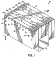
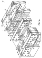
- Figs. 1, 1A, 2 and 3 illustrate a die apparatus 10 constructed in accordance with a first embodiment.
- Apparatus 10 is comprised of a manifold structure 12 coupled for fluid communication with an extrusion die 14.
- Manifold structure 12 is a lamellar construction or plate assembly comprised of multiple plates 16a-c, 18a-c and 20. These plates are securely fastened together in side-by-side relation using appropriate fasteners 22 (only one shown in Fig. 1) extending through holes 24 in each of the plates.
- respective outside pairs of plates 16a, 16b and 18a, 18b form process air manifold sections and include respective air input ports 26, 28.
- Plates 16a, 16b and 18a, 18b respectively abut each other and contain air passages 27, 29 therebetween.
- Air passages 27, 29 are respectively formed by pairs of recesses 30, 32 and 34, 36 that align with each other in abutting faces of the plates 16a, 16b and 18a, 18b.
- these recesses 30, 32 and 34, 36 take the form of so-called coat hangar recesses which become wider in dimension from the inlet portion 40 located proximate input ports 26, 28 to an outlet portion 42 located proximate respective distribution passages 44.
- Distribution passages 44 extend respectively through plates 16b and 18b and lead to similar distribution passages 46, 48 in plates 16c and 18c and, finally, into elongate air outlet slots 50, 52 which extend lengthwise along the undersides of plates 16c, 18c and communicate with coextensive elongate inlet slots 53, 55 in the top of the extrusion die 14. Plates 16c and 18c respectively abut central plate 20.
- Respective liquid passages 54, 56 are formed between plates 16c, 20 and 18c, 20 and, again, are formed by respective pairs of coat hangar recesses 58, 60 and 62, 64 that align with each other in abutting surfaces of these plates 16c, 20 and 18c, 20.
- these recesses 58, 60 and 62, 64 are also formed with a coat hangar configuration between inlet portions adjacent respective liquid input ports 66, 68 and outlet portions which form elongate liquid outlet slots 70, 72 for abutting the top surface of the extrusion die 14 and aligning with coextensive liquid inlet slots 73, 75.
- Extrusion die 14 may be any suitable extrusion die having, for example, a laminated plate construction with appropriate porting and passages to combine and extrude filaments from the outlet orifices extending along-the underside of the extrusion die 14 and to attenuate or otherwise affect those filaments with process air.
- Representative dies are, for example, disclosed in U.S. Patent Nos. 5,562,930; 5,551,588; and 5,344,297, however, such dies would require modification with suitable passages (not shown) to transfer and discharge process air received from air outlet slots 50, 52.
- heating elements 74, 76 are respectively contained in passages 80, 82 between plates 16b, 16c and 18b, 18c. Each passage is again preferably formed by respective pairs of aligned and abutting recesses 84, 86 and 88, 90 in plates 16b, 16c and 18b, 18c.
- These heating elements 74, 76 which are preferably electrically operated heating elements, may be advantageously situated between the respective air and liquid passages 27, 54 and 29, 56 so as to heat both the liquid and the air traveling to extrusion die 14. Sufficient heat may also be supplied to heat the extrusion die 14 itself to the appropriate operating temperature.
- FIGs. 4 and 5 illustrate another apparatus 100 constructed in accordance with the invention.
- apparatus 100 again comprises a multiple plate assembly or manifold structure 102 coupled with an extrusion die 104.
- Manifold structure 102 is similar to that described with respect to the first embodiment in that a seven plate construction 106a-c, 108a-c, 110 is used for providing both process air and two component liquids, such as polymers, to the extrusion die 104.
- two additional plates 112, 114 have been added to the outside of the manifold structure 102 to supply quenching air through respective input ports 116, 118 and air passages 120, 122 in the form of coat hangar passages as described above, and respective transfer passages 124, 126 and 128, 130 respectively extending through plates 106a, 106b and 108a, 108b and communicating with appropriate passages (not shown) in the extrusion die 104.
- This quenching air functions to cool the filaments after they have been discharged.
- input ports 140, 142 are provided for introducing two different component liquids, such as two different types of polymer materials, into apparatus 100.
- input ports 144, 146 are provided for process air. Liquid input ports 140, 142 communicate with respective pairs of abutting and aligned recesses 148, 150 and 152, 154 which form coat hangar passages and communicate directly with elongate slots (not shown) in the top of extrusion die 104.
- Input ports 144, 146 communicate with respective pairs of abutting recesses 156, 158 and 160, 162 in plates 106a, 106b and 108a, 108b.
- These recess 156, 158 and 160, 162 also form coat hanger air passages which communicate with respective elongate slots 164, 166 in plates 106c, 108c through respective transfer passages 168, 170 and 172, 174 in plates 106b, 106c and 108b, 108c to provide process or attenuating air to die 104.
- Passages 120, 122 are likewise formed as coat hangar passages formed by abutting recesses 176, 178 and 180, 182 having narrower portions adjacent input ports 116 and 118 and wider portions adjacent respective transfer passages 124 and 128.
- Electric heaters 184, 186 are provided as in the first embodiment.
- Fig. 6 illustrates another alternative die apparatus 200 having a laminated plate construction.
- This apparatus 200 is similar to that described above with respect to the first embodiment (Figs. 1, 1A, 2, 3), but is configured to discharge single component filaments or monofilaments rather than a bicomponent filament.
- the central plate 20 used in the first embodiment has been eliminated thereby resulting in a six plate construction rather than a seven plate construction for manifold structure 202.
- an extrusion die 204 is coupled to manifold structure 202 for discharging one or more filaments and, optionally, discharging air to facilitate a meltblowing operation.
- spunbond apparatus it will be appreciated that the process air passages and structure associated therewith may be eliminated.
- a single liquid input port 206 and coat hanger passage 208 receive the liquid, such as a thermoplastic polymer.
- Coat hanger passage 208 is formed by aligned recesses 210, 212 in abutting faces of plates 16c' and 18c'. Plates 16c' and 18c' are designated with prime marks (') to denote that they are slightly modified, as illustrated, from plates 16c, 18c. All other aspects of apparatus 200 are as described above with respect to the first embodiment and, therefore, identical reference numerals have been used and no further description is necessary.
- Fig. 7 illustrates another alternative apparatus 220 similar to that described above with respect to Figs. 4 and 5 but, like the embodiment of Fig. 6, apparatus 220 is configured to discharge single component filaments or monofilaments rather than bicomponent filaments.
- the central plate 110 of the embodiment illustrated in Figs. 4 and 5 has been eliminated and an eight plate manifold structure 222 results.
- Manifold structure 222 is configured to deliver liquid, process air and quench air to an extrusion die 224.
- a single liquid input port 206 and a coat hanger passage 208 is formed between abutting plates 106c', 108c' to communicate with an appropriate elongate inlet slot (not shown) in the top of the extrusion die 224.
- Plates 106c' and 108c' are designated with prime marks (') to denote that they are slightly modified, as illustrated, from plates 106c, 108c. All other aspects of the embodiment shown in Fig. 7 are described with respect to the embodiment of Figs. 4 and 5 and, therefore, identical reference numerals have been used and no further description is necessary.
Landscapes
- Engineering & Computer Science (AREA)
- Textile Engineering (AREA)
- Mechanical Engineering (AREA)
- Chemical & Material Sciences (AREA)
- Chemical Kinetics & Catalysis (AREA)
- General Chemical & Material Sciences (AREA)
- Spinning Methods And Devices For Manufacturing Artificial Fibers (AREA)
- Nonwoven Fabrics (AREA)
Applications Claiming Priority (2)
| Application Number | Priority Date | Filing Date | Title |
|---|---|---|---|
| US10/650,540 US7033153B2 (en) | 2003-08-28 | 2003-08-28 | Lamellar meltblowing die apparatus and method |
| US650540 | 2003-08-28 |
Publications (2)
| Publication Number | Publication Date |
|---|---|
| EP1512775A1 true EP1512775A1 (de) | 2005-03-09 |
| EP1512775B1 EP1512775B1 (de) | 2007-06-20 |
Family
ID=34136626
Family Applications (1)
| Application Number | Title | Priority Date | Filing Date |
|---|---|---|---|
| EP04020094A Expired - Lifetime EP1512775B1 (de) | 2003-08-28 | 2004-08-25 | Lamellare Schmelzblasspinndüse und Verfahren |
Country Status (3)
| Country | Link |
|---|---|
| US (1) | US7033153B2 (de) |
| EP (1) | EP1512775B1 (de) |
| DE (1) | DE602004007075T2 (de) |
Cited By (1)
| Publication number | Priority date | Publication date | Assignee | Title |
|---|---|---|---|---|
| CN103757714A (zh) * | 2011-10-09 | 2014-04-30 | 吴红平 | 适于大幅节能的纺丝箱用节能式纺丝模头 |
Families Citing this family (8)
| Publication number | Priority date | Publication date | Assignee | Title |
|---|---|---|---|---|
| US7125235B1 (en) * | 2003-03-03 | 2006-10-24 | Stark Patricia A | Pressurized plate-heated material die and method of constructing a pressurized plate-heated die |
| EP1512777B1 (de) * | 2003-08-23 | 2009-11-18 | Reifenhäuser GmbH & Co. KG Maschinenfabrik | Vorrichtung zur Erzeugung von Mehrkomponentenfasern, insbesondere von Bikomponentenfasern |
| USD536354S1 (en) | 2005-01-27 | 2007-02-06 | Nordson Corporation | Liquid spray applicator device |
| US20070205530A1 (en) * | 2006-03-02 | 2007-09-06 | Nordson Corporation | Apparatus and methods for distributing a balanced air stream to an extrusion die of a meltspinning apparatus |
| US7901195B2 (en) * | 2007-10-05 | 2011-03-08 | Spindynamics, Inc. | Attenuated fiber spinning apparatus |
| WO2014003761A1 (en) * | 2012-06-28 | 2014-01-03 | Dow Global Technologies Llc | System, method and apparatus for producing a multi-layer, microcapillary film |
| US10526729B2 (en) | 2014-02-24 | 2020-01-07 | Nanofiber, Inc. | Melt blowing die, apparatus and method |
| US20170120290A1 (en) * | 2015-11-01 | 2017-05-04 | Verdex Technologies Inc. | Apparatus and method for producing nanofibers from an array of two phase flow nozzles |
Citations (5)
| Publication number | Priority date | Publication date | Assignee | Title |
|---|---|---|---|---|
| US3501805A (en) * | 1963-01-03 | 1970-03-24 | American Cyanamid Co | Apparatus for forming multicomponent fibers |
| US3807917A (en) * | 1971-05-04 | 1974-04-30 | Exlan Co Ltd | Apparatus for spinning sheath-core type composite fibers |
| US5017116A (en) * | 1988-12-29 | 1991-05-21 | Monsanto Company | Spinning pack for wet spinning bicomponent filaments |
| EP0893517A2 (de) * | 1997-07-23 | 1999-01-27 | Anthony Fabbricante | Mikrodenierte Vliesstoffe hergestellt unter Verwendung von modular Spinndüsenplatteneinheiten |
| US6491507B1 (en) * | 2000-10-31 | 2002-12-10 | Nordson Corporation | Apparatus for meltblowing multi-component liquid filaments |
Family Cites Families (16)
| Publication number | Priority date | Publication date | Assignee | Title |
|---|---|---|---|---|
| US3613170A (en) * | 1969-05-27 | 1971-10-19 | American Cyanamid Co | Spinning apparatus for sheath-core bicomponent fibers |
| US3981650A (en) * | 1975-01-16 | 1976-09-21 | Beloit Corporation | Melt blowing intermixed filaments of two different polymers |
| US4406850A (en) * | 1981-09-24 | 1983-09-27 | Hills Research & Development, Inc. | Spin pack and method for producing conjugate fibers |
| DE3325310C2 (de) * | 1983-07-13 | 1986-01-30 | Metzeler Kautschuk GmbH, 8000 München | Vorrichtung zur Herstellung von Formteilen aus Kunststoff |
| US4818463A (en) * | 1986-04-26 | 1989-04-04 | Buehning Peter G | Process for preparing non-woven webs |
| WO1989002938A1 (en) * | 1987-10-02 | 1989-04-06 | Hills Research & Development, Inc. | Profiled multi-component fibers and method and apparatus for making same |
| US5162074A (en) * | 1987-10-02 | 1992-11-10 | Basf Corporation | Method of making plural component fibers |
| KR0125769B1 (ko) * | 1987-11-20 | 1997-12-29 | . | 부직 웨브의 제조방법 |
| US5145689A (en) * | 1990-10-17 | 1992-09-08 | Exxon Chemical Patents Inc. | Meltblowing die |
| ES2121077T3 (es) * | 1992-02-13 | 1998-11-16 | Accurate Prod Co | Matriz de soplado en caliente con paso de aire y de separacion preajustables. |
| JP3134959B2 (ja) * | 1992-03-17 | 2001-02-13 | チッソ株式会社 | 複合メルトブロー紡糸口金装置 |
| JP3360377B2 (ja) * | 1993-10-04 | 2002-12-24 | チッソ株式会社 | メルトブロー紡糸口金装置 |
| US5679379A (en) * | 1995-01-09 | 1997-10-21 | Fabbricante; Anthony S. | Disposable extrusion apparatus with pressure balancing modular die units for the production of nonwoven webs |
| DE19750724C2 (de) * | 1997-11-15 | 2003-04-30 | Reifenhaeuser Masch | Vorrichtung zum Herstellen eines Spinnvlieses aus Kern-Mantel-Struktur aufweisenden Bikomponentenfäden |
| US6478563B1 (en) * | 2000-10-31 | 2002-11-12 | Nordson Corporation | Apparatus for extruding multi-component liquid filaments |
| US7033154B2 (en) * | 2003-08-28 | 2006-04-25 | Nordson Corporation | Lamellar extrusion die apparatus and method |
-
2003
- 2003-08-28 US US10/650,540 patent/US7033153B2/en not_active Expired - Fee Related
-
2004
- 2004-08-25 DE DE602004007075T patent/DE602004007075T2/de not_active Expired - Fee Related
- 2004-08-25 EP EP04020094A patent/EP1512775B1/de not_active Expired - Lifetime
Patent Citations (5)
| Publication number | Priority date | Publication date | Assignee | Title |
|---|---|---|---|---|
| US3501805A (en) * | 1963-01-03 | 1970-03-24 | American Cyanamid Co | Apparatus for forming multicomponent fibers |
| US3807917A (en) * | 1971-05-04 | 1974-04-30 | Exlan Co Ltd | Apparatus for spinning sheath-core type composite fibers |
| US5017116A (en) * | 1988-12-29 | 1991-05-21 | Monsanto Company | Spinning pack for wet spinning bicomponent filaments |
| EP0893517A2 (de) * | 1997-07-23 | 1999-01-27 | Anthony Fabbricante | Mikrodenierte Vliesstoffe hergestellt unter Verwendung von modular Spinndüsenplatteneinheiten |
| US6491507B1 (en) * | 2000-10-31 | 2002-12-10 | Nordson Corporation | Apparatus for meltblowing multi-component liquid filaments |
Cited By (4)
| Publication number | Priority date | Publication date | Assignee | Title |
|---|---|---|---|---|
| CN103757714A (zh) * | 2011-10-09 | 2014-04-30 | 吴红平 | 适于大幅节能的纺丝箱用节能式纺丝模头 |
| CN103757716A (zh) * | 2011-10-09 | 2014-04-30 | 吴红平 | 导热效率较高的纺丝箱用节能式纺丝模头 |
| CN103757716B (zh) * | 2011-10-09 | 2015-12-30 | 广州科技职业技术学院 | 导热效率较高的纺丝箱用节能式纺丝模头 |
| CN103757714B (zh) * | 2011-10-09 | 2016-01-20 | 启东市希士水泥有限公司 | 适于大幅节能的纺丝箱用节能式纺丝模头 |
Also Published As
| Publication number | Publication date |
|---|---|
| US20050046090A1 (en) | 2005-03-03 |
| EP1512775B1 (de) | 2007-06-20 |
| US7033153B2 (en) | 2006-04-25 |
| DE602004007075D1 (de) | 2007-08-02 |
| DE602004007075T2 (de) | 2008-02-14 |
Similar Documents
| Publication | Publication Date | Title |
|---|---|---|
| JP4061371B2 (ja) | 複合液体フィラメントをメルトブローする装置 | |
| US6565344B2 (en) | Apparatus for producing multi-component liquid filaments | |
| AU2001277253B2 (en) | Process and system for producing multicomponent spunbonded nonwoven fabrics | |
| US7008586B2 (en) | Method of extruding multi-component liquid filaments | |
| EP1512775B1 (de) | Lamellare Schmelzblasspinndüse und Verfahren | |
| US20020125601A1 (en) | Apparatus and method for extruding single-component liquid strands into multi-component filaments | |
| US7160091B2 (en) | Device for the production of multicomponent fibers or filaments, in particular bicomponent fibers or filaments | |
| EP1512776B1 (de) | Lamellare Spinndüse und Verfahren | |
| WO2007103783A2 (en) | Apparatus for distributing a balanced air stream to an extrusion die | |
| US6773531B2 (en) | Process and apparatus for making multi-layered, multi-component filaments | |
| US7175407B2 (en) | Linear flow equalizer for uniform polymer distribution in a spin pack of a meltspinning apparatus |
Legal Events
| Date | Code | Title | Description |
|---|---|---|---|
| PUAI | Public reference made under article 153(3) epc to a published international application that has entered the european phase |
Free format text: ORIGINAL CODE: 0009012 |
|
| AK | Designated contracting states |
Kind code of ref document: A1 Designated state(s): AT BE BG CH CY CZ DE DK EE ES FI FR GB GR HU IE IT LI LU MC NL PL PT RO SE SI SK TR |
|
| AX | Request for extension of the european patent |
Extension state: AL HR LT LV MK |
|
| 17P | Request for examination filed |
Effective date: 20050909 |
|
| AKX | Designation fees paid |
Designated state(s): DE IT |
|
| GRAP | Despatch of communication of intention to grant a patent |
Free format text: ORIGINAL CODE: EPIDOSNIGR1 |
|
| GRAS | Grant fee paid |
Free format text: ORIGINAL CODE: EPIDOSNIGR3 |
|
| GRAA | (expected) grant |
Free format text: ORIGINAL CODE: 0009210 |
|
| RAP1 | Party data changed (applicant data changed or rights of an application transferred) |
Owner name: AKTIENGESELLSCHAFT ADOLPH SAURER |
|
| AK | Designated contracting states |
Kind code of ref document: B1 Designated state(s): DE IT |
|
| REF | Corresponds to: |
Ref document number: 602004007075 Country of ref document: DE Date of ref document: 20070802 Kind code of ref document: P |
|
| PGFP | Annual fee paid to national office [announced via postgrant information from national office to epo] |
Ref country code: DE Payment date: 20070904 Year of fee payment: 4 |
|
| PLBE | No opposition filed within time limit |
Free format text: ORIGINAL CODE: 0009261 |
|
| STAA | Information on the status of an ep patent application or granted ep patent |
Free format text: STATUS: NO OPPOSITION FILED WITHIN TIME LIMIT |
|
| 26N | No opposition filed |
Effective date: 20080325 |
|
| PG25 | Lapsed in a contracting state [announced via postgrant information from national office to epo] |
Ref country code: DE Free format text: LAPSE BECAUSE OF NON-PAYMENT OF DUE FEES Effective date: 20090303 |
|
| PGFP | Annual fee paid to national office [announced via postgrant information from national office to epo] |
Ref country code: IT Payment date: 20070831 Year of fee payment: 4 |