EP1512656A1 - Counterweight - Google Patents
Counterweight Download PDFInfo
- Publication number
- EP1512656A1 EP1512656A1 EP02738691A EP02738691A EP1512656A1 EP 1512656 A1 EP1512656 A1 EP 1512656A1 EP 02738691 A EP02738691 A EP 02738691A EP 02738691 A EP02738691 A EP 02738691A EP 1512656 A1 EP1512656 A1 EP 1512656A1
- Authority
- EP
- European Patent Office
- Prior art keywords
- counterweight
- car
- separated
- elevator system
- rotating body
- Prior art date
- Legal status (The legal status is an assumption and is not a legal conclusion. Google has not performed a legal analysis and makes no representation as to the accuracy of the status listed.)
- Granted
Links
Images


Classifications
-
- B—PERFORMING OPERATIONS; TRANSPORTING
- B66—HOISTING; LIFTING; HAULING
- B66B—ELEVATORS; ESCALATORS OR MOVING WALKWAYS
- B66B11/00—Main component parts of lifts in, or associated with, buildings or other structures
-
- B—PERFORMING OPERATIONS; TRANSPORTING
- B66—HOISTING; LIFTING; HAULING
- B66B—ELEVATORS; ESCALATORS OR MOVING WALKWAYS
- B66B17/00—Hoistway equipment
- B66B17/12—Counterpoises
Definitions
- the present invention relates to a counterweight. More particularly, the present invention relates to a counterweight for elevator system, which rises and lowers by being connected to a car rising and lowering in an elevator system.
- Figure 7 is a schematic view showing an outline of a traction type elevator system 200.
- the elevator system 200 has an elevator shaft 2.
- the upper part of the elevator shaft 2 is closed by a machine room floor 4, and a machine room 6 is provided above the floor 4.
- a hoisting machine 24 In the machine room 6 is provided a hoisting machine 24, and a rope 26 is wound around the hoisting machine 24. Both ends of the rope 26 hang from the machine room 4 into the elevator shaft 2. One end of the rope 26 is fixed to the car 8, and hangs the car 8 in the elevator shaft 2. The other end thereof is fixed to the counterweight 10, and hangs the counterweight 10 in the elevator shaft 2.
- the car 8 and the counterweight 10 are raised and lowered in the elevator shaft 2 by the movement of rope caused by the rotation of the hoisting machine 24.
- the car 8 and the counterweight 10 rise and lower with a some degree of weight balance in a state in which they are fixed to both ends of the rope 26. Also, the weight of the counterweight 10 is usually set at a half of the rated load of the car 8 considering the system efficiency.
- a buffer 60 is provided in the elevator system 200 at the lower part of the elevator shaft 2 on the counterweight 10 side.
- a shock can be absorbed to some degree, so that the shock can be eased as compared with the case where the counterweight 10 collides directly with the bottom of the elevator shaft 2.
- the counterweight 10 lowers in the elevator shaft 2 at a speed higher than the rated speed, it collides with the buffer 60 at a speed higher than the rated speed. In such a case, a great shock is given to the counterweight 10 as well as the car 8.
- an emergency stopper is installed under the car 8 or the counterweight 10, and a speed governor is provided in the machine room 6. Thereby, rapid movement of the car 8 at a speed higher than the rated speed is detected, and if the car 8 moves at a speed higher than the rated speed, a brake is applied to stop the car 8. Further, as another precaution, a rope brake such as to hold a main rope directly is sometimes provided. In operating the elevator system, various safety precautions are taken.
- the elevator system requires some degree of space. In installing the elevator system, however, space saving is often demanded strongly. Therefore, a safety device requiring a space for installation is not necessarily suitable. Also, when a device for directly holding the main rope to stop the elevator is used, the main rope may be worn early. Further, the safety devices of these types have complicated construction, so that a malfunction is liable to occur. Also, these devices are high in cost in most cases. In addition, when these devices are used, the braking force depends on the frictional force, so that the deceleration force during braking fluctuates greatly. Also, when the operation speed is high, the braking distance increases, and hence a shoe is worn, which may make braking operation impossible.
- the present invention proposes a counterweight for elevator system, which has been improved to solve the above problems and to easily prevent the moving speed of a car from becoming a speed higher than the rated speed.
- the present invention provides a counterweight which rises and lowers by being connected to a car rising and lowering in an elevator system, characterized in that the counterweight has an upper counterweight and a lower counterweight, and the upper counterweight and the lower counterweight can be separated from each other.
- the balance between the car and the counterweight can be adjusted by separating a part of the counterweight. Therefore, the rising and lowering speed can be alleviated, and hence a collision of the car or the counterweight with the bottom of an elevator shaft can be prevented, or the shock of collision can be eased.
- the upper counterweight when the counterweight is separated, the upper counterweight has an upper brake device for stopping the upper counterweight, and the lower counterweight has a lower brake device for stopping the lower counterweight.
- the upper counterweight and the lower counterweight that rise or lower are separated from each other and can be stopped individually. Therefore, the car can be stopped more easily, and the safety of elevator system can be ensured.
- the counterweight for elevator system in accordance with the present invention has a resetting means for connecting the upper counterweight and the lower counterweight to each other when the upper counterweight and the lower counterweight have been separated from each other. Thereby, even after the upper counterweight and the lower counterweight have been separated from each other, the connection can be resetting easily.
- Figure 1 is a schematic view of an elevator system 100 in accordance with an embodiment of the present invention.
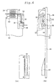
- Figure 2 is a schematic view for illustrating a construction of a counterweight 10 in the elevator system 100, in which Figure 2A being a front view and Figure 2B being a side view.
- Figure 2 shows an emergency brake arranged on the right-hand side in Figure 1 and a surrounding portion thereof.
- the elevator system 100 has an elevator shaft 2.
- the upper part of the elevator shaft 2 is closed by a machine room floor 4, and a machine room 6 is provided above the floor 4.
- the counterweight 10 is designed so as to have a weight that is a half of the rated load of the car 8.
- On the car 8 side of the elevator shaft 2 are provided guide rails 12, and the car 8 is connected to the guide rails 12 so as to be movable vertically.
- On the counterweight 10 side thereof are provided guide rails 14, and the counterweight 10 is connected to the guide rails 14 so as to be movable vertically.
- the machine room floor 4 is formed with two rope penetrating holes 20 and 22. Also, a hoisting machine 24 is provided in the machine room 6.
- a rope 26 is wound around the hoisting machine 24.
- One end of the rope 26 hangs from the machine room 6 into the elevator shaft 2 through the rope penetrating hole 20 formed in the machine room floor 4, and is fixed to the car 8 to hang the car 8 in the elevator shaft 2.
- the other end of the rope 26 hangs from the machine room 6 into the elevator shaft 2 through the rope passage 22 formed in the machine room floor 4, and is fixed to the counterweight 10 to hang the counterweight 10 in the elevator shaft 2.
- the counterweight 10 has an upper counterweight 30 and a lower counterweight 32.
- the lower counterweight 32 has a slightly lighter weight than the unmanned weight of the car 8.
- the weight of the upper counterweight 30 is set so that the weight of the whole of the counterweight 10 is a half of the rated load of the car 8 in a state where it is connected to the lower counterweight 32.
- an emergency brake Between the upper counterweight 30 and the lower counterweight 32 is provided an emergency brake.
- the upper counterweight 30 and the lower counterweight 32 are connected to the emergency brake.
- the rope 26 penetrates the upper counterweight 30 and is fixed to the upper part of the lower counterweight 32 only.
- the emergency brake includes a brake central portion 34, an upper brake element 36, and a lower brake element 38.
- the brake central portion 34 has a solenoid coil 40.
- the solenoid coil 40 is connected to a current source so that a current flows as necessary.
- a plunger 42 In the center of the solenoid coil 40 is provided a plunger 42.
- the upper brake element 36 is installed and fixed in the upper counterweight 30.
- the upper brake element 36 has a connecting rod 44.
- the connecting rod 44 has a through hole, and the plunger 42 of the brake central portion 34 passes through the through hole.
- the operating elastic member 46 is a spring-shaped elastic member formed by a strong wire.
- a roller 48 At one end of the connecting rod 44 is provided a roller 48.
- the roller 48 is a columnar member having a circular shape when viewed from the side.
- the upper brake element 36 has a wedge-shaped groove 50 formed above the roller 48.
- the groove 50 has a tapered shape such that the distance to the guide rail 14 decreases upward when viewed from the side.
- the lower brake element 38 is installed and fixed in the lower counterweight 32.
- the lower brake element 38 has a connecting rod 52.
- the connecting rod 52 has a through hole, and the plunger 42 of the brake central portion 34 passes through the through hole.
- the operating elastic member 54 is a spring-shaped elastic member formed by a strong wire.
- a roller 56 At one end of the connecting rod 52 is provided a roller 56.
- the roller 56 is a columnar member having a circular shape when viewed from the side.
- the upper brake element 38 has a wedge-shaped groove 58 formed below the roller 56.
- the groove 58 has a tapered shape such that the distance to the guide rail 14 decreases downward when viewed from the side.
- Figure 3 is a schematic view of the resetting plate.
- Figure 3A shows the resetting plate 16
- Figure 3B shows the resetting plate 18.
- the upper resetting plate 16 has a downward tapered shape
- the lower resetting plate 18 inversely has an upward tapered shape
- Figure 4 is a schematic view showing a state in which the emergency brake is operated in the elevator system 100.
- Figure 5 is a schematic view showing the state of the upper counterweight 30 at the time when the emergency brake is operated
- Figure 6 is a schematic view showing the state of the lower counterweight 32 at the time when the emergency brake is operated.
- Figures 5 and 6 each show the emergency brake arranged on the right-hand side in Figure 4 and a portion around the emergency brake.
- Figures 5A and 6A are front views
- Figures 5B and 6B are side views.
- the weight of the counterweight 10 is set so as to be a half of the rated load of the car 8. Therefore, for example, in the case where the hoisting machine 24 becomes uncontrollable due to a failure of the hoisting machine 24, breakage of a shaft, etc. during the time when the car 8 rises in a state such that the load in the car 8 is lower than a half load, that is, the counterweight 10 is heavier than the car 8, the rising speed of the car 8 increases, and the car 8 rises at a speed higher than the rated speed.
- the operation of the emergency brake in the case where the car 8 rises at an abnormal speed higher than the rated speed will be described.
- the counterweight 10 lowers at the same speed.
- the abnormality is detected, and a current flows in the solenoid coil 40 from a source current.
- the plunger 42 moves in the inside direction when viewed from the front, and the plunger 42 is pulled out of the through holes in the connecting rods 44 and 52.
- the upper brake element 36 and the lower brake element 38 are disconnected from each other. Therefore, as shown in Figure 4, the upper counterweight 30 is separated from the lower counterweight 32. At this time, the brake central portion 34 moves together with the lower brake element 38.
- the roller 48 When the upper counterweight 30 continues lowering, the roller 48 is subjected to the upward elastic force of the operating elastic member 46 and an upward frictional force generated between the roller 48 and the guide rail 14, so that the roller 48 is further pushed upward. Thereby, the roller 48 is gradually fitted and pressed between the wedge-shaped groove 50 having a tapered shape such that the distance to the guide rail 14 decreases upward and the guide rail 14.
- the upper brake element 36 When the roller 48 is fitted in the groove 50 completely, the upper brake element 36 is fixed to the guide rail 14, so that the upper counterweight 30 stops at an upper portion of the elevator shaft 2.
- the lower counterweight 32 continues lowering in a state in which the lower counterweight 32 and the car 8 are connected to each other by the rope 26.
- the lower counterweight 32 stops lowering after lowering to some degree, and inversely the lower counterweight 32 begins rising by being pulled by the car 8.
- the frictional force generated between the roller 56 and the guide rail 14 becomes a downward force, so that the roller 56 is pushed downward by this downward frictional force and the downward elastic force applied by the operating elastic member 54. Therefore, the roller 56 is gradually fitted in the groove 58 and is pressed between the groove 58 and the guide rail 14.
- the lower brake element 38 is fixed to the guide rail 14. Thereby, the lower counterweight 32 is stopped in an intermediate portion of the elevator shaft 2, whereby the car 8 is also stopped.
- the lower counterweight 32 is pushed down to a position at which the lower resetting plate 18 is provided by moving the elevator system 100 manually.
- an upward tapered portion of the resetting plate 18 automatically pushes up the roller 56 and removes it from the groove 58, so that the roller 56 is pushed back to the original position at which the lower counterweight 32 is connected to the upper counterweight 30.
- the plunger 42 can be reconnected to the connecting rod 52 automatically.
- the lower counterweight 32 is pushed up in this state together with the lower brake element 38 to the position at which the upper counterweight 30 stops, and successively the upper counterweight 30, i.e., the upper brake element 38 is pushed up together with the lower counterweight 32 to the position at which the upper resetting plate 16 is installed.
- a downward tapered portion of the resetting plate 16 automatically pushes down the roller 48 and removes it from the groove 50, so that the roller 28 is pushed back to the original position at which the upper counterweight 30 is connected to the lower counterweight 32.
- the plunger 42 is automatically connected to the connecting rod 52, by which the upper counterweight 30 can be connected to the lower counterweight 32.
- the lower counterweight 32 continues rising while being pulled by the car 8, by which the roller 56 is pushed downward by a downward elastic force of the operating elastic member 54 and a downward frictional force generated between the roller 56 and the guide rail 14. Therefore, the roller 56 fits in the groove 58, whereby the lower counterweight 32 is stopped.
- the unmanned load of the car 8 is set so as to be heavier than the weight of the lower counterweight 32, even if a failure occurs either when the load of the car 8 is lower than a half load or when the load thereof is higher than a half load, or either during the time when the car 8 rises or during the time when it lowers, the lower counterweight 32 is raised finally by being pulled to the car 8 side by the disconnection of the counterweight 10. Therefore, the roller 56 fits in the groove 58 during rising, whereby the lower counterweight 32 is stopped.
- the car 8 can be stopped by a simple device. Also, according to this device, the counterweight 10 can be separated easily by a simple mechanism, so that a machine malfunction is less liable to occur, and thus a highly reliable emergency brake can be installed.
- the shape, construction, and the like of the elevator system and the members thereof are not limited to those described in the above embodiment in the scope of the present invention.
- the plunger 42 and the connecting rods 44 and 52 are used as means for disconnecting the upper counterweight 30 and the lower counterweight 32 from each other.
- the present invention is not limited to the construction explained in this embodiment.
- the upper counterweight 30 and the lower counterweight 32 may be disconnected from each other, for example, by a device that is electrically controlled from the outside.
- a wedge effect using the rollers 48 and 56 and the grooves 50 and 58 is utilized as means for stopping the upper counterweight 30 and the lower counterweight 32.
- the present invention is not limited to the construction explained in this embodiment.
- the present invention is not limited to the elevator system having the emergency brake. Even in the case where the emergency brake is not provided, if the counterweight 10 can be separated into two, by setting the car 8 and the upper and lower counterweights so as to be imbalanced, the rising and lowering speed higher than the rated speed can be alleviated. Also, if such a counterweight and a buffer etc. having been used conventionally are used combinedly, a further safety precaution can be taken.
- upper and lower brake devices mean means for stopping the upper and lower counterweights, respectively.
- they correspond to the upper and lower brake elements 36 and 38 in this embodiment, respectively.
- upper and lower rotating bodies correspond to, for example, the rollers 48 and 56 in this embodiment, respectively.
- Upper and lower elastic members correspond to, for example, the operating elastic members 46 and 54, respectively.
- Upper and lower grooves correspond to, for example, the grooves 50 and 58, respectively.
- connecting means indicates means for connecting the upper and lower counterweights to each other, and corresponds to, for example, the brake central portion 34 in this embodiment.
- a connecting portion corresponds to, for example, the connecting rods 44 and 52 in this embodiment.
- a penetrating shaft corresponds to the plunger 42.
- a control unit corresponds to, for example, a portion including the solenoid coil 40 in this embodiment.
- resetting means indicates means for reconnecting the upper counterweight and the lower counterweight to each other when the upper counterweight and the lower counterweight have been disconnected from each other, and corresponds to, for example, the resetting plates 16 and 18 in this embodiment.
- the counterweight for elevator system can be separated into an upper part and a lower part. Therefore, during the time when the elevator system rises or lowers, by separating the counterweight as necessary, the balance between the car and the counterweight can be adjusted to decrease the rising and lowering speed.
- the elevator system can be stopped by a simple device, and safety in elevator operation can be ensured.
- the counterweights can easily be resetting to the original connected state after they have been separated. Therefore, the operation of the elevator system can be resetting rapidly without preparing complicated equipment, so that improvement in service and reduction in cost can be achieved.
Landscapes
- Engineering & Computer Science (AREA)
- Civil Engineering (AREA)
- Mechanical Engineering (AREA)
- Structural Engineering (AREA)
- Cage And Drive Apparatuses For Elevators (AREA)
Abstract
Description
- The present invention relates to a counterweight. More particularly, the present invention relates to a counterweight for elevator system, which rises and lowers by being connected to a car rising and lowering in an elevator system.
- Figure 7 is a schematic view showing an outline of a traction
type elevator system 200. - As shown in Figure 7, the
elevator system 200 has anelevator shaft 2. The upper part of theelevator shaft 2 is closed by a machine room floor 4, and amachine room 6 is provided above the floor 4. - In the
elevator shaft 2, acar 8 and acounterweight 10 are hung. - In the
machine room 6 is provided a hoistingmachine 24, and arope 26 is wound around the hoistingmachine 24. Both ends of therope 26 hang from the machine room 4 into theelevator shaft 2. One end of therope 26 is fixed to thecar 8, and hangs thecar 8 in theelevator shaft 2. The other end thereof is fixed to thecounterweight 10, and hangs thecounterweight 10 in theelevator shaft 2. - In the
elevator system 200 constructed as described above, thecar 8 and thecounterweight 10 are raised and lowered in theelevator shaft 2 by the movement of rope caused by the rotation of the hoistingmachine 24. - In such a traction
type elevator system 200, thecar 8 and thecounterweight 10 rise and lower with a some degree of weight balance in a state in which they are fixed to both ends of therope 26. Also, the weight of thecounterweight 10 is usually set at a half of the rated load of thecar 8 considering the system efficiency. - Therefore, for example, in the case where the load in the
car 8 is lower than a half of the rated load, if the movement of thecar 8 and thecounterweight 10 becomes incapable of being controlled because of a failure etc. of theelevator system 200 during the time when thecar 8 rises, it is thought that the rising speed of thecar 8 increases and thecar 8 rises at a speed higher than the rated speed because thecar 8 is lighter than thecounterweight 10. In this case, thecounterweight 10 moves downward at a speed higher than the rated speed. - As a precaution against such an emergency case, for example, a
buffer 60 is provided in theelevator system 200 at the lower part of theelevator shaft 2 on thecounterweight 10 side. By causing the loweringcounterweight 10 to collide with thebuffer 60, a shock can be absorbed to some degree, so that the shock can be eased as compared with the case where thecounterweight 10 collides directly with the bottom of theelevator shaft 2. However, even if the shock can be eased to some degree, when thecounterweight 10 lowers in theelevator shaft 2 at a speed higher than the rated speed, it collides with thebuffer 60 at a speed higher than the rated speed. In such a case, a great shock is given to thecounterweight 10 as well as thecar 8. - Also, as another precaution against the emergency case, for example, an emergency stopper is installed under the
car 8 or thecounterweight 10, and a speed governor is provided in themachine room 6. Thereby, rapid movement of thecar 8 at a speed higher than the rated speed is detected, and if thecar 8 moves at a speed higher than the rated speed, a brake is applied to stop thecar 8. Further, as another precaution, a rope brake such as to hold a main rope directly is sometimes provided. In operating the elevator system, various safety precautions are taken. - However, in order to install the above-described safety device for emergency stop, the elevator system requires some degree of space. In installing the elevator system, however, space saving is often demanded strongly. Therefore, a safety device requiring a space for installation is not necessarily suitable. Also, when a device for directly holding the main rope to stop the elevator is used, the main rope may be worn early. Further, the safety devices of these types have complicated construction, so that a malfunction is liable to occur. Also, these devices are high in cost in most cases. In addition, when these devices are used, the braking force depends on the frictional force, so that the deceleration force during braking fluctuates greatly. Also, when the operation speed is high, the braking distance increases, and hence a shoe is worn, which may make braking operation impossible.
- In the device in accordance with the invention proposed in Japanese Patent Laid-Open No. 5-193860, there is a structural time lag before the equipment is operated and a braking force is generated, so that the car may be accelerated due to the delayed time.
- Accordingly, the present invention proposes a counterweight for elevator system, which has been improved to solve the above problems and to easily prevent the moving speed of a car from becoming a speed higher than the rated speed.
- Therefore, the present invention provides a counterweight which rises and lowers by being connected to a car rising and lowering in an elevator system, characterized in that the counterweight has an upper counterweight and a lower counterweight, and the upper counterweight and the lower counterweight can be separated from each other. According to this construction, the balance between the car and the counterweight can be adjusted by separating a part of the counterweight. Therefore, the rising and lowering speed can be alleviated, and hence a collision of the car or the counterweight with the bottom of an elevator shaft can be prevented, or the shock of collision can be eased.
- Also, in the counterweight in accordance with the present invention, when the counterweight is separated, the upper counterweight has an upper brake device for stopping the upper counterweight, and the lower counterweight has a lower brake device for stopping the lower counterweight. According to this construction, the upper counterweight and the lower counterweight that rise or lower are separated from each other and can be stopped individually. Therefore, the car can be stopped more easily, and the safety of elevator system can be ensured.
- Also, the counterweight for elevator system in accordance with the present invention has a resetting means for connecting the upper counterweight and the lower counterweight to each other when the upper counterweight and the lower counterweight have been separated from each other. Thereby, even after the upper counterweight and the lower counterweight have been separated from each other, the connection can be resetting easily.
-
- Figure 1 is a schematic view of an elevator system in accordance with an embodiment of the present invention.
- Figure 2 is a schematic view for illustrating a construction of a counterweight of the elevator system in accordance with an embodiment of the present invention.
- Figure 3 is a schematic view of the resetting plate of the elevator system in accordance with an embodiment of the present invention.
- Figure 4 is a schematic view showing a state in which the emergency brake is operated in the elevator system in accordance with an embodiment of the present invention.
- Figure 5 is a schematic view showing the state of the upper counterweight at the time when the emergency brake is operated in the elevator system in accordance with an embodiment of the present invention.
- Figure 6 is a schematic view showing the state of the
lower counterweight 32 at the time when the emergency brake is operated in the elevator system in accordance with an embodiment of the present invention - Figure 7 is a schematic view showing an outline of a traction type elevator system.
-
- An embodiment of the present invention will now be described with reference to the accompanying drawings. In the figures, same reference numerals are applied to the same or corresponding elements, and the explanation of such elements is simplified or omitted.
- Figure 1 is a schematic view of an
elevator system 100 in accordance with an embodiment of the present invention. Also, Figure 2 is a schematic view for illustrating a construction of acounterweight 10 in theelevator system 100, in which Figure 2A being a front view and Figure 2B being a side view. Figure 2 shows an emergency brake arranged on the right-hand side in Figure 1 and a surrounding portion thereof. - As shown in Figure 1, the
elevator system 100 has anelevator shaft 2. The upper part of theelevator shaft 2 is closed by a machine room floor 4, and amachine room 6 is provided above the floor 4. - In the
elevator shaft 2, acar 8 and acounterweight 10 are hung. Thecounterweight 10 is designed so as to have a weight that is a half of the rated load of thecar 8. On thecar 8 side of theelevator shaft 2 are providedguide rails 12, and thecar 8 is connected to theguide rails 12 so as to be movable vertically. On thecounterweight 10 side thereof are providedguide rails 14, and thecounterweight 10 is connected to theguide rails 14 so as to be movable vertically. At the upper part and the lower part of theguide rail 14, there are provided resettingplates - The machine room floor 4 is formed with two
rope penetrating holes machine 24 is provided in themachine room 6. - A
rope 26 is wound around the hoistingmachine 24. One end of therope 26 hangs from themachine room 6 into theelevator shaft 2 through therope penetrating hole 20 formed in the machine room floor 4, and is fixed to thecar 8 to hang thecar 8 in theelevator shaft 2. The other end of therope 26 hangs from themachine room 6 into theelevator shaft 2 through therope passage 22 formed in the machine room floor 4, and is fixed to thecounterweight 10 to hang thecounterweight 10 in theelevator shaft 2. - In the
elevator system 100 constructed as described above, by the rotation of the hoistingmachine 24, therope 26 is moved according to the direction of rotation. Thereby, thecar 8 and thecounterweight 10 that are fixed to both ends of therope 26 are moved in theelevator shaft 2 along the guide rails 12 and 14. - Referring to Figures 1 and 2, the
counterweight 10 has anupper counterweight 30 and alower counterweight 32. Thelower counterweight 32 has a slightly lighter weight than the unmanned weight of thecar 8. Also, the weight of theupper counterweight 30 is set so that the weight of the whole of thecounterweight 10 is a half of the rated load of thecar 8 in a state where it is connected to thelower counterweight 32. Between theupper counterweight 30 and thelower counterweight 32 is provided an emergency brake. Theupper counterweight 30 and thelower counterweight 32 are connected to the emergency brake. Therope 26 penetrates theupper counterweight 30 and is fixed to the upper part of thelower counterweight 32 only. - As shown in Figure 2, the emergency brake includes a brake
central portion 34, anupper brake element 36, and alower brake element 38. - The brake
central portion 34 has asolenoid coil 40. Thesolenoid coil 40 is connected to a current source so that a current flows as necessary. In the center of thesolenoid coil 40 is provided aplunger 42. - The
upper brake element 36 is installed and fixed in theupper counterweight 30. Theupper brake element 36 has a connectingrod 44. The connectingrod 44 has a through hole, and theplunger 42 of the brakecentral portion 34 passes through the through hole. By this construction, the brakecentral portion 34 is connected to theupper brake element 36, and hence the brakecentral portion 34 is connected to theupper counterweight 30. - Around the connecting
rod 44 is wound an operatingelastic member 46. The operatingelastic member 46 is a spring-shaped elastic member formed by a strong wire. At one end of the connectingrod 44 is provided aroller 48. Theroller 48 is a columnar member having a circular shape when viewed from the side. Also, theupper brake element 36 has a wedge-shapedgroove 50 formed above theroller 48. Thegroove 50 has a tapered shape such that the distance to theguide rail 14 decreases upward when viewed from the side. - The
lower brake element 38 is installed and fixed in thelower counterweight 32. Thelower brake element 38 has a connectingrod 52. The connectingrod 52 has a through hole, and theplunger 42 of the brakecentral portion 34 passes through the through hole. By this construction, the brakecentral portion 34 is connected to thelower brake element 38, and hence the brakecentral portion 34 is connected to thelower counterweight 32. - Around the connecting
rod 52 is wound an operatingelastic member 54. The operatingelastic member 54 is a spring-shaped elastic member formed by a strong wire. At one end of the connectingrod 52 is provided aroller 56. Theroller 56 is a columnar member having a circular shape when viewed from the side. Also, theupper brake element 38 has a wedge-shapedgroove 58 formed below theroller 56. Thegroove 58 has a tapered shape such that the distance to theguide rail 14 decreases downward when viewed from the side. - Figure 3 is a schematic view of the resetting plate. Figure 3A shows the resetting
plate 16, and Figure 3B shows the resettingplate 18. - As shown in Figure 3, when viewed from the side, the
upper resetting plate 16 has a downward tapered shape, and thelower resetting plate 18 inversely has an upward tapered shape. - Figure 4 is a schematic view showing a state in which the emergency brake is operated in the
elevator system 100. Also, Figure 5 is a schematic view showing the state of theupper counterweight 30 at the time when the emergency brake is operated, and Figure 6 is a schematic view showing the state of thelower counterweight 32 at the time when the emergency brake is operated. Figures 5 and 6 each show the emergency brake arranged on the right-hand side in Figure 4 and a portion around the emergency brake. Figures 5A and 6A are front views, and Figures 5B and 6B are side views. - Next, the operation of the emergency brake will be described with reference to Figures 4 to 6.
- As described above, the weight of the
counterweight 10 is set so as to be a half of the rated load of thecar 8. Therefore, for example, in the case where the hoistingmachine 24 becomes uncontrollable due to a failure of the hoistingmachine 24, breakage of a shaft, etc. during the time when thecar 8 rises in a state such that the load in thecar 8 is lower than a half load, that is, thecounterweight 10 is heavier than thecar 8, the rising speed of thecar 8 increases, and thecar 8 rises at a speed higher than the rated speed. Herein, the operation of the emergency brake in the case where thecar 8 rises at an abnormal speed higher than the rated speed will be described. - First, when the
car 8 rises at an abnormal speed higher than the rated speed, thecounterweight 10 lowers at the same speed. At this time, in theelevator system 100, the abnormality is detected, and a current flows in thesolenoid coil 40 from a source current. When the current flows in thesolenoid coil 40, theplunger 42 moves in the inside direction when viewed from the front, and theplunger 42 is pulled out of the through holes in the connectingrods upper brake element 36 and thelower brake element 38 are disconnected from each other. Therefore, as shown in Figure 4, theupper counterweight 30 is separated from thelower counterweight 32. At this time, the brakecentral portion 34 moves together with thelower brake element 38. - As shown in Figure 5, when the
plunger 42 is pulled out of the connectingrod 44 of theupper brake element 36, theroller 48 is pushed upward by an elastic force of the operatingelastic member 46 provided around the connectingrod 44. Theroller 48 is pressed against theguide rail 14 as it moves upward along the wedge-shapedgroove 50. - When the
upper counterweight 30 continues lowering, theroller 48 is subjected to the upward elastic force of the operatingelastic member 46 and an upward frictional force generated between theroller 48 and theguide rail 14, so that theroller 48 is further pushed upward. Thereby, theroller 48 is gradually fitted and pressed between the wedge-shapedgroove 50 having a tapered shape such that the distance to theguide rail 14 decreases upward and theguide rail 14. When theroller 48 is fitted in thegroove 50 completely, theupper brake element 36 is fixed to theguide rail 14, so that theupper counterweight 30 stops at an upper portion of theelevator shaft 2. - On the other hand, as shown in Figure 6, when the
plunger 42 is pulled out of the connectingrod 52 of thelower brake element 38, theroller 56 is pushed downward by an elastic force of the operatingelastic member 54 provided around the connectingrod 52. Theroller 56 is pressed against theguide rail 14 as it moves downward slightly along the wedge-shapedgroove 58. At this time, since thelower brake element 38 lowers, a frictional force generated between theroller 56 and theguide rail 14 is an upward force as in the case of theroller 48 of theupper brake element 36. However, thegroove 58 of thelower brake element 38 has a tapered shape such that the distance to theguide rail 14 decreases downward contrary to thegroove 50 of theupper brake element 36. Therefore, theroller 56 is not fitted in thegroove 50 completely during lowering. - Therefore, the
lower counterweight 32 continues lowering in a state in which thelower counterweight 32 and thecar 8 are connected to each other by therope 26. However, at this time, since thecar 8 is heavier than thelower counterweight 32, thelower counterweight 32 stops lowering after lowering to some degree, and inversely thelower counterweight 32 begins rising by being pulled by thecar 8. At this time, the frictional force generated between theroller 56 and theguide rail 14 becomes a downward force, so that theroller 56 is pushed downward by this downward frictional force and the downward elastic force applied by the operatingelastic member 54. Therefore, theroller 56 is gradually fitted in thegroove 58 and is pressed between thegroove 58 and theguide rail 14. When theroller 56 fits in thegroove 58 completely, thelower brake element 38 is fixed to theguide rail 14. Thereby, thelower counterweight 32 is stopped in an intermediate portion of theelevator shaft 2, whereby thecar 8 is also stopped. - Next, the case where the upper and
lower counterweights lower counterweight 32 is pushed down to a position at which thelower resetting plate 18 is provided by moving theelevator system 100 manually. Thereupon, an upward tapered portion of the resettingplate 18 automatically pushes up theroller 56 and removes it from thegroove 58, so that theroller 56 is pushed back to the original position at which thelower counterweight 32 is connected to theupper counterweight 30. Thereby, theplunger 42 can be reconnected to the connectingrod 52 automatically. - Thereafter, the
lower counterweight 32 is pushed up in this state together with thelower brake element 38 to the position at which theupper counterweight 30 stops, and successively theupper counterweight 30, i.e., theupper brake element 38 is pushed up together with thelower counterweight 32 to the position at which theupper resetting plate 16 is installed. Thereupon, a downward tapered portion of the resettingplate 16 automatically pushes down theroller 48 and removes it from thegroove 50, so that the roller 28 is pushed back to the original position at which theupper counterweight 30 is connected to thelower counterweight 32. Thereby, theplunger 42 is automatically connected to the connectingrod 52, by which theupper counterweight 30 can be connected to thelower counterweight 32. - In the above description, the case where the
car 8 rises at a speed higher than the rated speed in the state in which the load in thecar 8 is lower than a half load in thecounterweight 10 has been explained. However, even in the case where thecar 8 lowers at a speed higher than the rated speed due to any failure or the like occurring in the state in which the load in thecar 8 is higher than a half load, that is, thecounterweight 10 is lighter than thecar 8, measures can be taken as described below by this elevator system. - In this case, when an abnormal speed is detected in the state in which the
counterweight 10 rises, a current flows in thesolenoid 40 as in the above-described case where thecounterweight 10 lowers, and hence theplunger 42 is moved to separate theupper counterweight 30 from thelower counterweight 32. At this time, since theupper counterweight 30 is not connected to therope 26, it stops rising immediately and begins lowering. Thereafter, theroller 48 fits in thegroove 50, and thereby theupper counterweight 30 is stopped as in the above-described case where a failure occurs during the time when thecounterweight 10 lowers. - On the otherhand, the
lower counterweight 32 continues rising while being pulled by thecar 8, by which theroller 56 is pushed downward by a downward elastic force of the operatingelastic member 54 and a downward frictional force generated between theroller 56 and theguide rail 14. Therefore, theroller 56 fits in thegroove 58, whereby thelower counterweight 32 is stopped. - As described above, according to this emergency brake, since the unmanned load of the
car 8 is set so as to be heavier than the weight of thelower counterweight 32, even if a failure occurs either when the load of thecar 8 is lower than a half load or when the load thereof is higher than a half load, or either during the time when thecar 8 rises or during the time when it lowers, thelower counterweight 32 is raised finally by being pulled to thecar 8 side by the disconnection of thecounterweight 10. Therefore, theroller 56 fits in thegroove 58 during rising, whereby thelower counterweight 32 is stopped. - On the other hand, since the separated
upper counterweight 30 is not connected to thecar 8, it lowers finally in either case where thecar 8 is rising or lowering. Therefore, during lowering, theroller 48 fits in thegroove 50, whereby theupper counterweight 30 is stopped. - Thus, even if the
car 8 begins rising or lowering at a speed higher than the rated speed due to a failure of the hoistingmachine 24 etc. when the weights of thecar 8 and thecounterweight 10 are imbalanced, thecar 8 can be stopped by a simple device. Also, according to this device, thecounterweight 10 can be separated easily by a simple mechanism, so that a machine malfunction is less liable to occur, and thus a highly reliable emergency brake can be installed. - In this
elevator system 100, even if theupper counterweight 30 and thelower counterweight 32 are separated from each other, they can be connected easily by manually moving theelevator system 100. Therefore, a simple emergency brake can be installed without a need for preparing a complicated device. - Also, according to this
elevator system 100, since the emergency brake is installed in thecounterweight 10, a special installation space is unnecessary, so that space saving can be achieved. - In the present invention, the shape, construction, and the like of the elevator system and the members thereof are not limited to those described in the above embodiment in the scope of the present invention.
- In this embodiment, the
plunger 42 and the connectingrods upper counterweight 30 and thelower counterweight 32 from each other. However, the present invention is not limited to the construction explained in this embodiment. Theupper counterweight 30 and thelower counterweight 32 may be disconnected from each other, for example, by a device that is electrically controlled from the outside. - Also, in this embodiment, a wedge effect using the
rollers grooves upper counterweight 30 and thelower counterweight 32. However, the present invention is not limited to the construction explained in this embodiment. - Also, in this embodiment, a description has been given of the elevator system in which the
counterweight 10 is separated into two, and the emergency brake for completely stopping the upper andlower counterweights counterweight 10 can be separated into two, by setting thecar 8 and the upper and lower counterweights so as to be imbalanced, the rising and lowering speed higher than the rated speed can be alleviated. Also, if such a counterweight and a buffer etc. having been used conventionally are used combinedly, a further safety precaution can be taken. - In the present invention, upper and lower brake devices mean means for stopping the upper and lower counterweights, respectively. For example, they correspond to the upper and
lower brake elements - Also, in the present invention, upper and lower rotating bodies correspond to, for example, the
rollers elastic members grooves - Also, in the present invention, connecting means indicates means for connecting the upper and lower counterweights to each other, and corresponds to, for example, the brake
central portion 34 in this embodiment. A connecting portion corresponds to, for example, the connectingrods plunger 42. - Also, in the present invention, a control unit corresponds to, for example, a portion including the
solenoid coil 40 in this embodiment. - Also, in the present invention, resetting means indicates means for reconnecting the upper counterweight and the lower counterweight to each other when the upper counterweight and the lower counterweight have been disconnected from each other, and corresponds to, for example, the resetting
plates - As described above, according to the present invention, the counterweight for elevator system can be separated into an upper part and a lower part. Therefore, during the time when the elevator system rises or lowers, by separating the counterweight as necessary, the balance between the car and the counterweight can be adjusted to decrease the rising and lowering speed.
- Also, in the present invention, if the upper and lower brake devices are provided in the separated counterweights, the elevator system can be stopped by a simple device, and safety in elevator operation can be ensured.
- Also, in the present invention, if the resetting means is provided, the counterweights can easily be resetting to the original connected state after they have been separated. Therefore, the operation of the elevator system can be resetting rapidly without preparing complicated equipment, so that improvement in service and reduction in cost can be achieved.
Claims (7)
- A counterweight which rises and lowers by being connected to a car rising and lowering in an elevator system, characterized in that
said counterweight comprises an upper counterweight and a lower counterweight; and
said upper counterweight and said lower counterweight can be separated from each other. - The counterweight according to claim 1, characterized in that
said upper counterweight is provided with an upper brake device for stopping said upper counterweight when said counterweight is separated; and
said lower counterweight is providedwith a lower brake device for stopping said lower counterweight when said counterweight is separated. - The counterweight according to claim 2, characterized in that
said counterweight rises and lowers along a guide rail provided in an elevator shaft of the elevator system;
said upper brake device comprises an upper rotating body installed so as to be movable in the advance direction when said counterweight is separated,
an upper elastic member for pushing said upper rotating body upward when said counterweight is separated, and
an upper groove provided above said upper rotating body so as to have a tapered shape such that the distance to said guide rail decreases upward; and
when said upper counterweight moves downward, said upper rotating body is pushed up and fitted between said upper groove and said guide rail to stop said upper counterweight. - The counterweight according to claim 2 or 3, characterized in that
said counterweight rises and lowers along a guide rail provided in an elevator shaft of the elevator system;
said lower brake device comprises a lower rotating body installed so as to be movable in the advance direction when said counterweight is separated,
a lower elastic member for pushing said lower rotating body downward when said counterweight is separated, and
a lower groove provided below said lower rotating body so as to have a tapered shape such that the distance to said guide rail decreases downward; and
when said lower counterweight moves upward, said lower rotating body is pushed down and fitted between said lower groove and said guide rail to stop said lower counterweight. - The counterweight for elevator system according to any one of claims 1 to 4, characterized in that
said counterweight has connecting means for connecting said upper counterweight and said lower counterweight to each other;
said upper counterweight and said lower counterweight each have a connecting portion formed with a through hole;
said connecting means has a penetrating shaft capable of passing through said through holes; and
said upper counterweight and said lower counterweight are connected to each other by causing said penetrating shaft to pass through said through holes. - The counterweight according to claim 5, characterized in that
said connecting means is connected to a control unit for sensing the rising or lowering movement of said car and/or said counterweight when said car and/or said counterweight rises or lowers at an abnormal speed higher than a predetermined speed; and
said penetrating shaft is removed from said through holes in said connecting portions by a signal sent from said control unit to separate said upper counterweight from said lower counterweight. - The counterweight according to any one of claims 1 to 6, characterized in that said counterweight is provided with a resetting means for connecting said upper counterweight and said lower counterweight to each other when said upper counterweight and said lower counterweight have been separated from each other.
Applications Claiming Priority (1)
| Application Number | Priority Date | Filing Date | Title |
|---|---|---|---|
| PCT/JP2002/005905 WO2003106321A1 (en) | 2002-06-13 | 2002-06-13 | Counterweight |
Publications (3)
| Publication Number | Publication Date |
|---|---|
| EP1512656A1 true EP1512656A1 (en) | 2005-03-09 |
| EP1512656A4 EP1512656A4 (en) | 2008-11-12 |
| EP1512656B1 EP1512656B1 (en) | 2010-03-17 |
Family
ID=29727350
Family Applications (1)
| Application Number | Title | Priority Date | Filing Date |
|---|---|---|---|
| EP02738691A Expired - Lifetime EP1512656B1 (en) | 2002-06-13 | 2002-06-13 | Counterweight |
Country Status (6)
| Country | Link |
|---|---|
| EP (1) | EP1512656B1 (en) |
| JP (1) | JPWO2003106321A1 (en) |
| KR (1) | KR100569799B1 (en) |
| CN (1) | CN1285500C (en) |
| DE (1) | DE60235727D1 (en) |
| WO (1) | WO2003106321A1 (en) |
Cited By (3)
| Publication number | Priority date | Publication date | Assignee | Title |
|---|---|---|---|---|
| WO2010081935A1 (en) * | 2009-01-15 | 2010-07-22 | Kone Corporation | Elevator |
| WO2011032582A1 (en) * | 2009-09-16 | 2011-03-24 | Manuela Widmann | Emergency rescue system, in particular for elevators |
| US20130248299A1 (en) * | 2010-12-01 | 2013-09-26 | Kone Corporation | Elevator arrangement and method |
Families Citing this family (8)
| Publication number | Priority date | Publication date | Assignee | Title |
|---|---|---|---|---|
| US7656641B2 (en) * | 2006-12-21 | 2010-02-02 | General Electric Company | Apparatus and method for controlling a solenoid |
| JP5354898B2 (en) * | 2007-12-26 | 2013-11-27 | 株式会社日立製作所 | Elevator counterweight |
| CN101407301A (en) * | 2008-11-17 | 2009-04-15 | 吕安文 | Lifting device without energy consumption |
| CN102126663A (en) * | 2011-03-07 | 2011-07-20 | 邬建勋 | Trackless counter weight assembly and trackless lift car |
| JP5777742B2 (en) * | 2014-01-14 | 2015-09-09 | 株式会社東芝 | Elevator equipment |
| WO2019012695A1 (en) * | 2017-07-14 | 2019-01-17 | 三菱電機株式会社 | Elevator counterweight device |
| JP2019183214A (en) * | 2018-04-06 | 2019-10-24 | 光洋サーモシステム株式会社 | Heat treatment device |
| CN117902437B (en) * | 2024-03-15 | 2024-07-09 | 浙江飞亚电梯有限公司 | Elevator counterweight balancing device convenient to install |
Citations (2)
| Publication number | Priority date | Publication date | Assignee | Title |
|---|---|---|---|---|
| US1073700A (en) * | 1913-02-20 | 1913-09-23 | Neenan Elevator Company | Rope elevator. |
| WO2002034658A1 (en) * | 2000-10-20 | 2002-05-02 | Kabushiki Kaisha Toshiba | Elevator without machine room |
Family Cites Families (4)
| Publication number | Priority date | Publication date | Assignee | Title |
|---|---|---|---|---|
| JPH06263368A (en) * | 1993-03-12 | 1994-09-20 | Otis Elevator Co | Balance weight for elevator |
| JPH0797161A (en) * | 1993-09-27 | 1995-04-11 | Fuji Hensokuki Kk | Balance weight of lift device |
| US5495919A (en) * | 1994-04-25 | 1996-03-05 | Otis Elevator Company | Safety brake apparatus for an elevator car or counterweight |
| JP2001080837A (en) * | 1999-09-13 | 2001-03-27 | Hitachi Ltd | Elevator device |
-
2002
- 2002-06-13 CN CNB028171462A patent/CN1285500C/en not_active Expired - Fee Related
- 2002-06-13 EP EP02738691A patent/EP1512656B1/en not_active Expired - Lifetime
- 2002-06-13 WO PCT/JP2002/005905 patent/WO2003106321A1/en active Application Filing
- 2002-06-13 DE DE60235727T patent/DE60235727D1/en not_active Expired - Lifetime
- 2002-06-13 JP JP2004513160A patent/JPWO2003106321A1/en active Pending
- 2002-06-13 KR KR1020047001986A patent/KR100569799B1/en not_active IP Right Cessation
Patent Citations (2)
| Publication number | Priority date | Publication date | Assignee | Title |
|---|---|---|---|---|
| US1073700A (en) * | 1913-02-20 | 1913-09-23 | Neenan Elevator Company | Rope elevator. |
| WO2002034658A1 (en) * | 2000-10-20 | 2002-05-02 | Kabushiki Kaisha Toshiba | Elevator without machine room |
Non-Patent Citations (1)
| Title |
|---|
| See also references of WO03106321A1 * |
Cited By (3)
| Publication number | Priority date | Publication date | Assignee | Title |
|---|---|---|---|---|
| WO2010081935A1 (en) * | 2009-01-15 | 2010-07-22 | Kone Corporation | Elevator |
| WO2011032582A1 (en) * | 2009-09-16 | 2011-03-24 | Manuela Widmann | Emergency rescue system, in particular for elevators |
| US20130248299A1 (en) * | 2010-12-01 | 2013-09-26 | Kone Corporation | Elevator arrangement and method |
Also Published As
| Publication number | Publication date |
|---|---|
| JPWO2003106321A1 (en) | 2005-10-13 |
| DE60235727D1 (en) | 2010-04-29 |
| KR20040021694A (en) | 2004-03-10 |
| CN1549789A (en) | 2004-11-24 |
| CN1285500C (en) | 2006-11-22 |
| KR100569799B1 (en) | 2006-04-10 |
| EP1512656B1 (en) | 2010-03-17 |
| WO2003106321A1 (en) | 2003-12-24 |
| EP1512656A4 (en) | 2008-11-12 |
Similar Documents
| Publication | Publication Date | Title |
|---|---|---|
| JP6012596B2 (en) | Elevator equipment | |
| US9637348B2 (en) | Elevator apparatus | |
| US9505587B2 (en) | Elevator with acceleration detection | |
| EP3674247A1 (en) | Elevator with an electrical linear motor | |
| KR20140042769A (en) | Arrangement for actuating and restoring an intercepting apparatus | |
| EP1512656B1 (en) | Counterweight | |
| EP3643666B1 (en) | Elevator system | |
| US10773923B2 (en) | Method for avoiding unwanted safety gear tripping in an elevator system, controller adapted to perform such a method, governor brake and elevator system each having such a controller | |
| US9663325B2 (en) | Braking apparatus and elevator hoisting machine that uses same | |
| EP3456674B1 (en) | Elevator tension member slack detection system and method of performing an emergency stop operation of an elevator system | |
| JP6062009B2 (en) | Elevator equipment | |
| US9604819B2 (en) | Elevator monitoring arrangement configured to monitor operation of a safety device of an elevator, a controller and method for performing same | |
| US11597633B2 (en) | Elevator safety brake, elevator and method for testing elevator safety brakes | |
| US7419033B2 (en) | Emergency brake device for elevator | |
| JP2016204061A (en) | Elevator device | |
| JPH05338959A (en) | Linear motor driven elevator device | |
| EP3689804A1 (en) | Elevator safety brake, elevator and method for testing elevator safety brakes | |
| JP6172082B2 (en) | Double deck elevator |
Legal Events
| Date | Code | Title | Description |
|---|---|---|---|
| PUAI | Public reference made under article 153(3) epc to a published international application that has entered the european phase |
Free format text: ORIGINAL CODE: 0009012 |
|
| 17P | Request for examination filed |
Effective date: 20040120 |
|
| AK | Designated contracting states |
Kind code of ref document: A1 Designated state(s): AT BE CH CY DE DK ES FI FR GB GR IE IT LI LU MC NL PT SE TR |
|
| RBV | Designated contracting states (corrected) |
Designated state(s): DE |
|
| RAP1 | Party data changed (applicant data changed or rights of an application transferred) |
Owner name: MITSUBISHI DENKI KABUSHIKI KAISHA |
|
| A4 | Supplementary search report drawn up and despatched |
Effective date: 20081013 |
|
| 17Q | First examination report despatched |
Effective date: 20090204 |
|
| GRAP | Despatch of communication of intention to grant a patent |
Free format text: ORIGINAL CODE: EPIDOSNIGR1 |
|
| GRAS | Grant fee paid |
Free format text: ORIGINAL CODE: EPIDOSNIGR3 |
|
| GRAA | (expected) grant |
Free format text: ORIGINAL CODE: 0009210 |
|
| AK | Designated contracting states |
Kind code of ref document: B1 Designated state(s): DE |
|
| REF | Corresponds to: |
Ref document number: 60235727 Country of ref document: DE Date of ref document: 20100429 Kind code of ref document: P |
|
| PLBE | No opposition filed within time limit |
Free format text: ORIGINAL CODE: 0009261 |
|
| STAA | Information on the status of an ep patent application or granted ep patent |
Free format text: STATUS: NO OPPOSITION FILED WITHIN TIME LIMIT |
|
| 26N | No opposition filed |
Effective date: 20101220 |
|
| PGFP | Annual fee paid to national office [announced via postgrant information from national office to epo] |
Ref country code: DE Payment date: 20130605 Year of fee payment: 12 |
|
| REG | Reference to a national code |
Ref country code: DE Ref legal event code: R119 Ref document number: 60235727 Country of ref document: DE |
|
| REG | Reference to a national code |
Ref country code: DE Ref legal event code: R119 Ref document number: 60235727 Country of ref document: DE Effective date: 20150101 |
|
| PG25 | Lapsed in a contracting state [announced via postgrant information from national office to epo] |
Ref country code: DE Free format text: LAPSE BECAUSE OF NON-PAYMENT OF DUE FEES Effective date: 20150101 |