EP1512581B1 - Siège de véhicule - Google Patents
Siège de véhicule Download PDFInfo
- Publication number
- EP1512581B1 EP1512581B1 EP03255568A EP03255568A EP1512581B1 EP 1512581 B1 EP1512581 B1 EP 1512581B1 EP 03255568 A EP03255568 A EP 03255568A EP 03255568 A EP03255568 A EP 03255568A EP 1512581 B1 EP1512581 B1 EP 1512581B1
- Authority
- EP
- European Patent Office
- Prior art keywords
- squab
- seat
- edge
- inner part
- outer part
- Prior art date
- Legal status (The legal status is an assumption and is not a legal conclusion. Google has not performed a legal analysis and makes no representation as to the accuracy of the status listed.)
- Expired - Lifetime
Links
Images



Classifications
-
- B—PERFORMING OPERATIONS; TRANSPORTING
- B60—VEHICLES IN GENERAL
- B60N—SEATS SPECIALLY ADAPTED FOR VEHICLES; VEHICLE PASSENGER ACCOMMODATION NOT OTHERWISE PROVIDED FOR
- B60N2/00—Seats specially adapted for vehicles; Arrangement or mounting of seats in vehicles
- B60N2/02—Seats specially adapted for vehicles; Arrangement or mounting of seats in vehicles the seat or part thereof being movable, e.g. adjustable
- B60N2/04—Seats specially adapted for vehicles; Arrangement or mounting of seats in vehicles the seat or part thereof being movable, e.g. adjustable the whole seat being movable
- B60N2/16—Seats specially adapted for vehicles; Arrangement or mounting of seats in vehicles the seat or part thereof being movable, e.g. adjustable the whole seat being movable height-adjustable
- B60N2/1605—Seats specially adapted for vehicles; Arrangement or mounting of seats in vehicles the seat or part thereof being movable, e.g. adjustable the whole seat being movable height-adjustable characterised by the cinematic
-
- B—PERFORMING OPERATIONS; TRANSPORTING
- B60—VEHICLES IN GENERAL
- B60N—SEATS SPECIALLY ADAPTED FOR VEHICLES; VEHICLE PASSENGER ACCOMMODATION NOT OTHERWISE PROVIDED FOR
- B60N2/00—Seats specially adapted for vehicles; Arrangement or mounting of seats in vehicles
- B60N2/02—Seats specially adapted for vehicles; Arrangement or mounting of seats in vehicles the seat or part thereof being movable, e.g. adjustable
- B60N2/04—Seats specially adapted for vehicles; Arrangement or mounting of seats in vehicles the seat or part thereof being movable, e.g. adjustable the whole seat being movable
- B60N2/16—Seats specially adapted for vehicles; Arrangement or mounting of seats in vehicles the seat or part thereof being movable, e.g. adjustable the whole seat being movable height-adjustable
- B60N2/1605—Seats specially adapted for vehicles; Arrangement or mounting of seats in vehicles the seat or part thereof being movable, e.g. adjustable the whole seat being movable height-adjustable characterised by the cinematic
- B60N2/161—Rods
- B60N2/1615—Parallelogram-like structure
-
- B—PERFORMING OPERATIONS; TRANSPORTING
- B60—VEHICLES IN GENERAL
- B60N—SEATS SPECIALLY ADAPTED FOR VEHICLES; VEHICLE PASSENGER ACCOMMODATION NOT OTHERWISE PROVIDED FOR
- B60N2/00—Seats specially adapted for vehicles; Arrangement or mounting of seats in vehicles
- B60N2/02—Seats specially adapted for vehicles; Arrangement or mounting of seats in vehicles the seat or part thereof being movable, e.g. adjustable
- B60N2/04—Seats specially adapted for vehicles; Arrangement or mounting of seats in vehicles the seat or part thereof being movable, e.g. adjustable the whole seat being movable
- B60N2/16—Seats specially adapted for vehicles; Arrangement or mounting of seats in vehicles the seat or part thereof being movable, e.g. adjustable the whole seat being movable height-adjustable
- B60N2/1605—Seats specially adapted for vehicles; Arrangement or mounting of seats in vehicles the seat or part thereof being movable, e.g. adjustable the whole seat being movable height-adjustable characterised by the cinematic
- B60N2/1625—Combination of rods and slides
-
- B—PERFORMING OPERATIONS; TRANSPORTING
- B60—VEHICLES IN GENERAL
- B60N—SEATS SPECIALLY ADAPTED FOR VEHICLES; VEHICLE PASSENGER ACCOMMODATION NOT OTHERWISE PROVIDED FOR
- B60N2/00—Seats specially adapted for vehicles; Arrangement or mounting of seats in vehicles
- B60N2/90—Details or parts not otherwise provided for
- B60N2/986—Side-rests
- B60N2/99—Side-rests adjustable
-
- B—PERFORMING OPERATIONS; TRANSPORTING
- B60—VEHICLES IN GENERAL
- B60R—VEHICLES, VEHICLE FITTINGS, OR VEHICLE PARTS, NOT OTHERWISE PROVIDED FOR
- B60R7/00—Stowing or holding appliances inside vehicle primarily intended for personal property smaller than suit-cases, e.g. travelling articles, or maps
- B60R7/04—Stowing or holding appliances inside vehicle primarily intended for personal property smaller than suit-cases, e.g. travelling articles, or maps in driver or passenger space, e.g. using racks
- B60R7/043—Stowing or holding appliances inside vehicle primarily intended for personal property smaller than suit-cases, e.g. travelling articles, or maps in driver or passenger space, e.g. using racks mounted on or under a seat
-
- B—PERFORMING OPERATIONS; TRANSPORTING
- B60—VEHICLES IN GENERAL
- B60N—SEATS SPECIALLY ADAPTED FOR VEHICLES; VEHICLE PASSENGER ACCOMMODATION NOT OTHERWISE PROVIDED FOR
- B60N2205/00—General mechanical or structural details
- B60N2205/30—Seat or seat parts characterised by comprising plural parts or pieces
Definitions
- This invention relates to vehicle seats.
- vehicle seats In particular it relates to a vehicle seat which retains items placed on the seat while the vehicle is in motion (sse, for example, DE 197 35 098 A , corresponding to the preamble of claim 1).
- the edge may be raised relative to squab.
- the edge may be up to 50mm higher than the squab in its displaced position.
- friction retains the edge and squab in their relative positions.
- the outer part of the squab may be hinged at the back of the seat relative to the inner part, such that the outer part may be raised relative to the inner part to form a lip which extends across the front and sides of the inner part.
- the outer part of the squab may move by means of a linkage mechanism such that the outer part is raised relative to the inner part to form a lip of substantially even height extending across the front and sides of the inner part of the squab.
- a conventional car seat 1 comprises a squab 3 for sitting on, a back 5 and a headrest 7 as shown in Fig. 1 .
- Such seats are conventionally mounted within a vehicle such that an occupant faces in the direction of travel with the squab 3 being forward of the seat back 5 in relation to the usual direction of motion of the vehicle.
- the terms 'front' and 'back' are used herein to indicate forward and rearward positions respectively on a conventionally mounted seat in relation to the usual direction of motion.
- the seat shown in Figs. 1 and 2 further comprises a two-part squab having an inner part 3 and an edge or outer part 9.
- the inner part 3 is static and mounted on a seat pan (not shown) as per a conventional car seat.
- the outer part 9 is mounted on a separate seat pan which is hinged at its back edge. This enables the front edge of the outer part 9 to be raised by lifting the outer part 9 at its front edge relative to the hinged back edge and the inner part 3, to form a raised wall or lip 13 which extends partially round the inner part 3 of the squab across the front and sides as shown in Fig. 2 .
- the front edge of the outer part may be raised to form a lip 13 approximately 50mm in height relative to the inner part 3 at its front edge. Friction between the inner and outer parts retains the outer part in its raised position until such time as it is pushed down again.
- the driver may deposit any personal items he/she wishes to be easily accessible during or at the end of the journey on the passenger seat squab. He/she then lifts the outer part 9 of the squab at its front edge as indicated by arrow 11 to form a raised wall or lip 13 which extends across the front and sides of the inner part 3 of the squab and surrounds the deposited items. The driver may then embark on his/her journey. Tests have shown that a lip of up to 50mm in height relative to the inner part 3 of the squab is sufficient to prevent personal items placed on the seat from falling into the passenger footwell or into the gaps either side of the seat during firm braking and cornering.
- any items placed on the seat may be removed and the outer part 9 of the squab simply pushed back down to its lowered position, either by hand or by the action of the passenger sitting on the seat.
- the outer part of the squab may be raised relative to the static inner part, it will be clear that as an alternative the inner part of the squab could be lowered relative to a static outer part, or indeed both parts could be movable to create the wall round the squab.
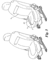
- an alternative not forming part of the present invention might include a linkage mechanism which enables the edge to be raised at the back of the seat as well as the front. This would have the advantage of providing a raised lip of substantially even height round the inner part of the squab, as shown in Fig. 3 .
- a linkage mechanism is shown in more detail in Figs. 4a and 4b , and comprises four parallel linkages, two on either side of the seat towards its front and back (only one side of the seat is shown in the figures). Each linkage comprises a primary strut 15 and a secondary strut 16.
- the primary strut 15 is hinged at its upper end 19 to the outer part 9 of the squab while its lower end 17 is free to slide back and forth along a rail 18.
- the secondary strut 16 is hinged at its lower end 20 at a position just in front of the rail 18, and at its upper end to a mid-point along the primary strut 15.
- the inner part 3 of the squab is statically attached to the seat base (not shown).
- Fig. 4a shows the outer part 9 of the squab in a lowered position suitable for occupancy by a passenger.
- the outer part 9 of the squab may be raised by lifting it such that the secondary struts 16 pivot about their lower hinges 20 while the lower ends 17 of the primary struts 15 slide forward in rails 18, and the upper ends 19 of the primary struts 15 move straight up as indicated by arrows 21 in the detailed view of the linkage shown in Fig. 4b , until it reaches its raised position as shown in Fig. 4b , while the inner part 3 of the squab remains unmoved.
- the outer part 9 of the squab In its raised position, the outer part 9 of the squab forms a raised lip 23 of substantially even height surrounding sides and front of the inner part 3 of the squab to prevent personal items placed on the seat from falling into the passenger footwell or into the gaps either side of the seat during firm braking and cornering.
- the outer part 9 of the squab may be lowered simply by pushing it downwards such that it returns to its lowered position.
- a simple ratchet mechanism underneath the squab may be used to prevent the parts from moving under the influence of vibrations.
- a spring-loaded mechanism with a catch and release button may be used to raise/lower and retain the outer or inner parts in this position.
- a further alternative would be to operate the outer or inner part of the squab electrically by means of a motor, switch and appropriate gearing in the same way as other electric seat adjustments are made. If the outer part of the squab were operated in this way, the gearing could include a slip device to allow for the outer part of the squab to be pushed down so as not to require powering down before it could be sat on.
Landscapes
- Engineering & Computer Science (AREA)
- Mechanical Engineering (AREA)
- Aviation & Aerospace Engineering (AREA)
- Transportation (AREA)
- Seats For Vehicles (AREA)
Claims (6)
- Siège de véhicule (1) comprenant un coussin (3) pour s'asseoir dessus, le siège (1) comprenant en outre un bord (9), le coussin (3) et/ou le bord (9) pouvant se déplacer l'un par rapport à l'autre entre une première position dans laquelle le bord n'est pas substantiellement plus haut que le coussin et une deuxième position dans laquelle le bord (9) est plus haut que le coussin, de telle sorte que le bord (9) forme une paroi au moins en partie autour de la surface supérieure du coussin (3) pour retenir des articles placés sur le siège (1) tandis que le véhicule se déplace, caractérisé en ce que le coussin (3) est un coussin en deux parties ayant une partie extérieure (9) et une partie intérieure (3), la partie extérieure (9) formant le bord et étant articulée à l'arrière du siège par rapport à la partie intérieure (3), de telle sorte que la partie extérieure (9) puisse être relevée par rapport à la partie intérieure (3) pour former une lèvre (13) qui s'étend en travers de l'avant et des côtés de la partie intérieure (3).
- Siège de véhicule (1) selon la revendication 1, caractérisé en ce que le bord (9) peut être relevé par rapport au coussin (3).
- Siège de véhicule (1) selon la revendication 1 ou 2, caractérisé en ce que, lorsqu'il est déplacé, le bord (9) peut être jusqu'à 50 mm plus haut que le coussin (3).
- Siège de véhicule (1) selon l'une quelconque des revendications précédentes, caractérisé en ce que le bord (9) et le coussin (3) sont retenus dans leurs positions relatives par friction.
- Siège de véhicule (1) selon l'une quelconque des revendications 1 à 3, dans lequel le bord (9) et le coussin (3) peuvent se déplacer l'un par rapport à l'autre au moyen d'un mécanisme à rochet, chargé à ressort ou électrique.
- Automobile comprenant un siège selon l'une quelconque des revendications précédentes.
Priority Applications (2)
| Application Number | Priority Date | Filing Date | Title |
|---|---|---|---|
| EP03255568A EP1512581B1 (fr) | 2003-09-06 | 2003-09-06 | Siège de véhicule |
| DE60326840T DE60326840D1 (de) | 2003-09-06 | 2003-09-06 | Fahrzeugsitz |
Applications Claiming Priority (1)
| Application Number | Priority Date | Filing Date | Title |
|---|---|---|---|
| EP03255568A EP1512581B1 (fr) | 2003-09-06 | 2003-09-06 | Siège de véhicule |
Publications (2)
| Publication Number | Publication Date |
|---|---|
| EP1512581A1 EP1512581A1 (fr) | 2005-03-09 |
| EP1512581B1 true EP1512581B1 (fr) | 2009-03-25 |
Family
ID=34130345
Family Applications (1)
| Application Number | Title | Priority Date | Filing Date |
|---|---|---|---|
| EP03255568A Expired - Lifetime EP1512581B1 (fr) | 2003-09-06 | 2003-09-06 | Siège de véhicule |
Country Status (2)
| Country | Link |
|---|---|
| EP (1) | EP1512581B1 (fr) |
| DE (1) | DE60326840D1 (fr) |
Families Citing this family (2)
| Publication number | Priority date | Publication date | Assignee | Title |
|---|---|---|---|---|
| FR2920359B1 (fr) * | 2007-08-31 | 2009-11-06 | Peugeot Citroen Automobiles Sa | Bac de rangement pour siege arriere amovible |
| JP6533564B2 (ja) * | 2017-10-24 | 2019-06-19 | 本田技研工業株式会社 | ヘッドレスト収納構造 |
Citations (1)
| Publication number | Priority date | Publication date | Assignee | Title |
|---|---|---|---|---|
| US6161896A (en) * | 1999-10-13 | 2000-12-19 | Daimlerchrysler Corporation | Automotive vehicle rear seat storage system |
Family Cites Families (8)
| Publication number | Priority date | Publication date | Assignee | Title |
|---|---|---|---|---|
| US3309135A (en) * | 1964-10-28 | 1967-03-14 | Jannetto John | Package retaining rack apparatus |
| JPH07277082A (ja) * | 1994-04-14 | 1995-10-24 | Araco Corp | 車両用シート |
| DE9412066U1 (de) * | 1994-07-26 | 1994-09-22 | Bechthold, Werner, 67487 St Martin | Vorrichtung zum sicheren Ablegen von Gegenständen auf Kraftfahrzeugsitzen |
| JPH09150679A (ja) * | 1995-11-29 | 1997-06-10 | Kanto Auto Works Ltd | 自動車座席用トレイ兼用手荷物保持具 |
| JPH1035364A (ja) * | 1996-07-24 | 1998-02-10 | Showa Aircraft Ind Co Ltd | 書籍ホルダー付の助手席 |
| DE19735098C2 (de) * | 1997-08-13 | 2000-03-23 | Hillebrand Jun | Sitz für ein Fahrzeug |
| US5908218A (en) * | 1998-01-13 | 1999-06-01 | Martin; Steve | Devices for restricting the movements of objects |
| FR2783217B1 (fr) * | 1998-09-10 | 2000-10-13 | Peugeot | Dispositif de rangement integre a un siege de vehicule automobile |
-
2003
- 2003-09-06 EP EP03255568A patent/EP1512581B1/fr not_active Expired - Lifetime
- 2003-09-06 DE DE60326840T patent/DE60326840D1/de not_active Expired - Lifetime
Patent Citations (1)
| Publication number | Priority date | Publication date | Assignee | Title |
|---|---|---|---|---|
| US6161896A (en) * | 1999-10-13 | 2000-12-19 | Daimlerchrysler Corporation | Automotive vehicle rear seat storage system |
Also Published As
| Publication number | Publication date |
|---|---|
| EP1512581A1 (fr) | 2005-03-09 |
| DE60326840D1 (de) | 2009-05-07 |
Similar Documents
| Publication | Publication Date | Title |
|---|---|---|
| JP3768467B2 (ja) | 車両用シート構造 | |
| US7445261B2 (en) | Console assembly for a vehicle | |
| EP1894786A2 (fr) | Console centrale à double coulissement | |
| US6921118B2 (en) | Sliding and nesting console system | |
| EP1449710B1 (fr) | Dispositif de siège comprenant un siège auxiliaire escamotable | |
| US6547326B1 (en) | Automotive seat flip-out cupholder | |
| US7784843B2 (en) | Vehicle console with sliding panel | |
| CN107054176B (zh) | 带中央垫体和控制台扶手的车辆座椅 | |
| US6905155B1 (en) | Multiple height load floor system | |
| CN108790959A (zh) | 车辆乘客舱 | |
| GB2468566A (en) | Console container rail system | |
| CN113799670A (zh) | 机动车辆的中央控制台 | |
| WO1999042329A1 (fr) | Sieges de vehicules a moteur | |
| GB2395118A (en) | Seat assembly having a table extending from upper backrest | |
| US20070295875A1 (en) | Stowable Cup Holder Tray Assembly | |
| US20070075559A1 (en) | Console assembly having integrated media storage | |
| EP1461225B1 (fr) | Siege pour vehicule a moteur comportant un element agenouilloir | |
| US6027164A (en) | Combination seat and armrest with storage compartments | |
| WO2000013931A1 (fr) | Siege de vehicule dote d'un dossier presentant une structure exterieure fixe et un sas interieur | |
| GB2412849A (en) | Vehicle seat assembly | |
| EP1512581A1 (fr) | Siège de véhicule | |
| KR20240050803A (ko) | 자동차 무버블 콘솔 | |
| JP6316103B2 (ja) | 車両用スロープ及びそれを備えた車両 | |
| EP1787856B1 (fr) | Dispositif de stockage | |
| EP0808740A3 (fr) | Mécanisme de réglage de la hauteur d'un siège de véhicles automobiles |
Legal Events
| Date | Code | Title | Description |
|---|---|---|---|
| PUAI | Public reference made under article 153(3) epc to a published international application that has entered the european phase |
Free format text: ORIGINAL CODE: 0009012 |
|
| AK | Designated contracting states |
Kind code of ref document: A1 Designated state(s): AT BE BG CH CY CZ DE DK EE ES FI FR GB GR HU IE IT LI LU MC NL PT RO SE SI SK TR |
|
| AX | Request for extension of the european patent |
Extension state: AL LT LV MK |
|
| 17P | Request for examination filed |
Effective date: 20050818 |
|
| AKX | Designation fees paid |
Designated state(s): DE FR GB |
|
| RAP1 | Party data changed (applicant data changed or rights of an application transferred) |
Owner name: FORD GLOBAL TECHNOLOGIES, LLC. |
|
| 17Q | First examination report despatched |
Effective date: 20080509 |
|
| GRAP | Despatch of communication of intention to grant a patent |
Free format text: ORIGINAL CODE: EPIDOSNIGR1 |
|
| GRAS | Grant fee paid |
Free format text: ORIGINAL CODE: EPIDOSNIGR3 |
|
| GRAA | (expected) grant |
Free format text: ORIGINAL CODE: 0009210 |
|
| AK | Designated contracting states |
Kind code of ref document: B1 Designated state(s): DE FR GB |
|
| REG | Reference to a national code |
Ref country code: GB Ref legal event code: FG4D |
|
| REF | Corresponds to: |
Ref document number: 60326840 Country of ref document: DE Date of ref document: 20090507 Kind code of ref document: P |
|
| PLBE | No opposition filed within time limit |
Free format text: ORIGINAL CODE: 0009261 |
|
| STAA | Information on the status of an ep patent application or granted ep patent |
Free format text: STATUS: NO OPPOSITION FILED WITHIN TIME LIMIT |
|
| 26N | No opposition filed |
Effective date: 20091229 |
|
| REG | Reference to a national code |
Ref country code: FR Ref legal event code: PLFP Year of fee payment: 14 |
|
| REG | Reference to a national code |
Ref country code: FR Ref legal event code: PLFP Year of fee payment: 15 |
|
| REG | Reference to a national code |
Ref country code: FR Ref legal event code: PLFP Year of fee payment: 16 |
|
| PGFP | Annual fee paid to national office [announced via postgrant information from national office to epo] |
Ref country code: DE Payment date: 20190813 Year of fee payment: 17 Ref country code: FR Payment date: 20190819 Year of fee payment: 17 |
|
| PGFP | Annual fee paid to national office [announced via postgrant information from national office to epo] |
Ref country code: GB Payment date: 20190827 Year of fee payment: 17 |
|
| REG | Reference to a national code |
Ref country code: DE Ref legal event code: R119 Ref document number: 60326840 Country of ref document: DE |
|
| GBPC | Gb: european patent ceased through non-payment of renewal fee |
Effective date: 20200906 |
|
| PG25 | Lapsed in a contracting state [announced via postgrant information from national office to epo] |
Ref country code: FR Free format text: LAPSE BECAUSE OF NON-PAYMENT OF DUE FEES Effective date: 20200930 Ref country code: DE Free format text: LAPSE BECAUSE OF NON-PAYMENT OF DUE FEES Effective date: 20210401 |
|
| PG25 | Lapsed in a contracting state [announced via postgrant information from national office to epo] |
Ref country code: GB Free format text: LAPSE BECAUSE OF NON-PAYMENT OF DUE FEES Effective date: 20200906 |