EP1512548A2 - Classeur et la méthode pour sa présentation - Google Patents
Classeur et la méthode pour sa présentation Download PDFInfo
- Publication number
- EP1512548A2 EP1512548A2 EP04078273A EP04078273A EP1512548A2 EP 1512548 A2 EP1512548 A2 EP 1512548A2 EP 04078273 A EP04078273 A EP 04078273A EP 04078273 A EP04078273 A EP 04078273A EP 1512548 A2 EP1512548 A2 EP 1512548A2
- Authority
- EP
- European Patent Office
- Prior art keywords
- arch
- cover
- coupling means
- spine
- file
- Prior art date
- Legal status (The legal status is an assumption and is not a legal conclusion. Google has not performed a legal analysis and makes no representation as to the accuracy of the status listed.)
- Withdrawn
Links
- 238000000034 method Methods 0.000 title claims description 13
- 230000008878 coupling Effects 0.000 claims abstract description 31
- 238000010168 coupling process Methods 0.000 claims abstract description 31
- 238000005859 coupling reaction Methods 0.000 claims abstract description 31
- 239000004033 plastic Substances 0.000 claims abstract description 11
- 229920003023 plastic Polymers 0.000 claims abstract description 11
- 238000001746 injection moulding Methods 0.000 claims abstract description 9
- 238000002347 injection Methods 0.000 claims description 9
- 239000007924 injection Substances 0.000 claims description 9
- 238000002372 labelling Methods 0.000 claims description 8
- 230000000295 complement effect Effects 0.000 claims 1
- 210000001364 upper extremity Anatomy 0.000 description 9
- 239000000123 paper Substances 0.000 description 7
- 238000004519 manufacturing process Methods 0.000 description 6
- 239000002184 metal Substances 0.000 description 3
- 239000000463 material Substances 0.000 description 2
- 239000011230 binding agent Substances 0.000 description 1
- 230000007423 decrease Effects 0.000 description 1
- 239000006223 plastic coating Substances 0.000 description 1
Images


Classifications
-
- B—PERFORMING OPERATIONS; TRANSPORTING
- B42—BOOKBINDING; ALBUMS; FILES; SPECIAL PRINTED MATTER
- B42F—SHEETS TEMPORARILY ATTACHED TOGETHER; FILING APPLIANCES; FILE CARDS; INDEXING
- B42F13/00—Filing appliances with means for engaging perforations or slots
- B42F13/0006—Covers for loose-leaf binders
- B42F13/0066—Covers for loose-leaf binders with means for attaching the filing appliance to the cover
- B42F13/0073—Covers for loose-leaf binders with means for attaching the filing appliance to the cover removable
Definitions
- the invention relates to a file.
- the invention particularly relates to a file with at least an arch for fixing paper and the like.
- Files are conventionally provided with a front cover, a back cover and a spine, manufactured from cardboard, if required enclosed in a plastic coating sealed therearound.
- Front cover, back cover and spine are interconnected by hinges.
- Fixed on the back cover is an arch by means of pop rivets, blind rivets or the like, by which a fixed connection is obtained.
- the arch consists mainly of, for instance, two, four or twenty ring elements, which can be divided by means of an opening and closing mechanism, so that paper with perforations can be slid thereon, after which the rings are closed to fix the paper.
- Such files are, for instance, known as multi-ring, two-ring or four-ring files or the like.
- the invention has for its object to provide a file of the type described in the opening paragraph, in which the above disadvantages are avoided, while retaining the advantages thereof.
- a file according to the invention is characterized by the features of claim 1.
- the advantage is obtained that the arch or arches and the cover, built up from front cover, back cover and spine, can be manufactured, stored and transported apart from each other, while they can be relatively simply coupled to compose a suitable file.
- the cover is manufactured by injection molding with integrated hinges, with first coupling means being co-formed, while the arches are provided with second coupling means, for cooperation therewith.
- Injection molding of the cover has the advantage that it can be formed in a very rapid and simple manner, without sharp parts and consisting of one piece, so that further production steps are not necessary, other than the above simple coupling of first and second coupling means, preferably directly before use.
- the covers can simply be stacked flat on each other, in open condition or in folded condition, while the arches can be packed separately. As a result, the files occupy very little space.
- the or each arch can be slid with the second coupling means in the form of guide means into the first coupling means in the form of further guide means and can be fixed therein by resilient clamping means.
- the first coupling means may be co-injection molded in plastic, but may also be co-injection molded as inserts, for instance metal or plastic inserts.
- the covers When plastic injection molding the covers, it is preferred that at least a part of the outside of the cover, in particular a part of the spine, is provided with a surface that can be written on, in particular by labeling. In a very advantageous form, use is thereby made of in-mold labeling. As a result, a file with a pleasant appearance and practical usability can be obtained in an even simpler manner.
- the cover for that matter, can be provided, in particular on the outside, with a desired structure by in-mold labeling.
- the cover is preferably provided with stiffening means, such as ribs, ridges or the like, preferably on the side of the cover facing inward.
- stiffening means such as ribs, ridges or the like
- the invention further relates to a set of a cover and at least an arch, the cover being provided with first coupling means and the arch with second coupling means, such that the or each arch can be easily connected with a cover to form a file.
- the invention relates to a method for presenting files, characterized by the measures of claim 12.
- covers can be packed in flat or folded condition, at least stacked in a relatively small space, while the arches can be stored apart therefrom. Only later, for instance just before use, do the files need to be composed.
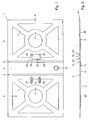
- Fig. 1 shows, in open condition, seen from the inside, a cover 1 for a file 100 according to the invention, which cover is provided with a front cover 2, a back cover 3 and a spine 4, hingedly interconnected via hinges 5, 6.
- the cover 1 is preferably manufactured in one piece by injection molding, for instance as specified below, in a mold as shown in Figs. 8 and 9.
- the cover may be simply injection molded in the relatively flat position shown in Figs. 1 and 2, the hinges 5, 6 being of the living hinge type. Suitable plastics will be directly clear to those skilled in the art.
- stiffening ribs 7 and a slightly thickened edge 8 are provided, the edge being rounded on the outside 9 for embellishment and to simplify the manufacture. Moreover, such a rounding is advantageous during use and damage is thereby prevented in a simpler manner.
- an opening 10 in the spine 4 is shown an opening 10, as usual in files, through which, for instance, a finger can be put to pull the file out of a cabinet.
- the cover 1, in particular the spine 4 can be simply provided on the outside with parts that can be written on, for instance by in-mold labeling.
- a finishing layer, for instance texture may be provided by means of in-mold labeling technique, printing technique or the like. Texture may also be obtained by appropriate adjustment of the respective wall parts of the mold.
- first coupling means 12 On the back cover 3 near the spine 4 are provided first coupling means 12 in which an arch 13, for instance as shown in Fig. 3, can be fixed after forming the cover 1, more in particular previous to use of the file 100.
- arches 13 are sufficiently known from practice for files. The arch 13 will therefore not be described in more detail as far as not necessary for a proper understanding of the invention.
- the arch 13 comprises a baseplate 14, for instance with a substantially rectangular, rounded outer form.
- Fastened to the baseplate are two bent front legs 15 and interconnected back legs 16, which are likewise bent and can be moved against the front legs 15 or pivoted away therefrom by means of a lever 17, in which latter position paper and the like can be slid over the front legs 15 with appropriate perforations.
- the front legs 15 are connected with the baseplate 14 in a position-stable manner.
- the baseplate 14 and the front legs 15 together substantially form second coupling means 18, which can cooperate with the first coupling means 12, in a manner to be specified, for fixing the arch 13 in the cover 1.
- the first coupling means comprise guide means 20, which can cooperate with at least a longitudinal edge 21 of the baseplate 14 as second guide means, two clamping means 22 being provided in the first coupling means for fixing the arch 13 in the guide means 20.
- the clamping means 22 are provided with recesses 23, in which the front legs 15 can be fixed.
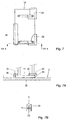
- Figs. 5 - 7 is specified in three steps how the arch is fixed in the first coupling means 12.
- the arch 13 is shown in Figs. 5 - 7 only diagrammatically, while omitting the pivoting arm 17, spring means 19 and the like.
- the legs 15, 16 are shown on the baseplate 14 in cross-section, the further legs 15, 16 being diagrammatically shown therebetween (in projection).
- the first coupling means 12 comprise a first guide means 20 in the form of a substantially straight guide with an approximately L-shaped cross-section.
- this guide element 20 is placed such that the longitudinal edge 21 of the baseplate 14 can be slid thereunder over, for instance, half the length L of the baseplate 14, such that the longitudinal edge 21 is held thereunder.
- the clamping elements 22 each comprise a flange 26, which extend approximately parallel to the surface 25 of the back cover 3, in which flanges 26 the recesses 23 are provided.
- the recesses 23 are open toward the side facing the guide element 20.
- a tongue 28 is provided behind each recess 23, which tongue projects from the wall 29 farther than the opposite flange part 30 and serves as catch means.
- the arch 13 can be placed as follows.
- the arch is placed with the baseplate 14 on the back cover 3, slightly beside the, in Figs. 5, 6 and 7 upper, clamping element 22, the baseplate 14 being slightly rotated, such that the longitudinal axis I thereof encloses an angle a with the slide-in direction S.
- the first arch 31, shown at the bottom of Fig. 5 is slid along the upper clamping element 22A to between the guide element 20 and the flange part 30 of the lower clamping element 22B. This position is shown in Fig. 6.
- the arch 13 is pushed further in the slide-in direction S, thereby slightly elastically deforming at least the clamping elements 22, until the lower arch 31 strikes against the tongue 28 of the lower clamping element 22B, while the respective front leg 15 of the arch 31 is received in the respective recess 23. Then the front leg 15 of the other arch 32 will be automatically received in the opening 23 of the, in Fig. 6 upper, clamping element 22A, such that the longitudinal axis I is rotated back, until it extends parallel to the slide-in direction S. In this condition, the arch 13 is secured in the first coupling means 12 against any movement, as shown in Fig. 7.
- the guide element 20 and/or the clamping elements 22, which are slightly elastically deformed when slid in, will assume their original form again to even better fix the arch 13.
- a further recess may be provided in the horizontal flange 33 of the guide element 20, in which recess the back leg 16 of the lower arch 31 can be received, so that the arch 13 is even better secured against movement, in particular rotation.
- pins which extend approximately at right angles to the surface 25 or enclose an obtuse angle therewith, which pins can elastically deform when the baseplate 14 is slid on and can spring back into openings in the baseplate, while, again, for instance longitudinal edges 21, 24 of the baseplate 14 are guided by guide elements, such as guide element 20.
- a file 100 according to the invention can be used as follows.
- a series of covers 1 is placed in flat condition in a container, for instance a box, in which the covers 1 can be simply packed in a compact manner.
- An equal number of arches 13 is packed apart from the covers 1, at least separately therefrom. In this condition, the arches are transported to users.
- a cover 1 is taken from the container, an arch 13 is fixed thereon, preferably in the manner as described above, after which the file is ready for use. Paper and the like, as shown in Fig. 4 in broken lines, can be fixed on the arch 13, in a manner known per se.
- the file 100 can be closed by folding the front cover 2 over the paper P.
- the front cover 2 Provided in the front cover 2 are two openings 40 with clamping lips 41, as in known files, with which the front cover 2 can be fixed on the arch 13, in particular the legs 15, 16.
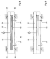
- a mold 50 comprising a first part 51 and a second part 52, in which second part 52 is provided a movable wall part 53, operable from outside the mold 50 by arms 54, diagrammatically shown in Figs. 8 and 9.
- a mold cavity 55 Provided inside the mold 50 is a mold cavity 55, a part of which is defined by the movable wall part 53, in which mold cavity 55 the cover 1 can be formed.
- plastic is brought into the mold cavity 55 with withdrawn movable wall part 53, that is to say the space of the mold cavity 55 is relatively large.
- a cover 1 is formed in a completely dimensionally stable manner. It is clear that during injection molding the mold 50 is kept closed, as diagrammatically shown by closure elements 56. With such a method, a cover that is relatively dimensionally stable can be manufactured in a very simple manner, using relatively light tools, while, moreover, a high degree of freedom in the choice of plastic is obtained. In fact, as a result of the movable wall part, broad flow paths are obtained during the largest part of the filling of the mold, so that both high-melt and very low-melt plastics can be used.
- the arches may be fixed on the cover in various manners.
- screw means, clamping means and the like may also be used, in particular for the use of a described method in which covers and arches are delivered separately and are only composed preferably directly before use.
- special advantages are obtained, in particular during storage and transport.
- other types of materials may be used as well, for instance covers partly or completely formed from cardboard or plastic plate and the like.
- Covers for use in a file according to the invention may also be injection molded in another manner, in other more conventional injection molding devices.
- different arches may be used as well, for instance two-, three- or multi-ring binders that can be fixed on a cover in the same or in a comparable manner.
- arches may also be placed from an outside of the cover, by pushing the legs through slit-shaped openings and fixing them on the inside.
Landscapes
- Moulds For Moulding Plastics Or The Like (AREA)
- Sheet Holders (AREA)
Applications Claiming Priority (3)
| Application Number | Priority Date | Filing Date | Title |
|---|---|---|---|
| NL1019739A NL1019739C2 (nl) | 2002-01-14 | 2002-01-14 | Ordner en werkwijze voor aanbieden van ordners. |
| NL1019739 | 2002-01-14 | ||
| EP03701930A EP1467875A1 (fr) | 2002-01-14 | 2003-01-14 | Classeurs et procede de presentation de classeurs |
Related Parent Applications (1)
| Application Number | Title | Priority Date | Filing Date |
|---|---|---|---|
| EP03701930.4 Division | 2003-01-14 |
Publications (1)
| Publication Number | Publication Date |
|---|---|
| EP1512548A2 true EP1512548A2 (fr) | 2005-03-09 |
Family
ID=19774456
Family Applications (2)
| Application Number | Title | Priority Date | Filing Date |
|---|---|---|---|
| EP03701930A Withdrawn EP1467875A1 (fr) | 2002-01-14 | 2003-01-14 | Classeurs et procede de presentation de classeurs |
| EP04078273A Withdrawn EP1512548A2 (fr) | 2002-01-14 | 2003-01-14 | Classeur et la méthode pour sa présentation |
Family Applications Before (1)
| Application Number | Title | Priority Date | Filing Date |
|---|---|---|---|
| EP03701930A Withdrawn EP1467875A1 (fr) | 2002-01-14 | 2003-01-14 | Classeurs et procede de presentation de classeurs |
Country Status (7)
| Country | Link |
|---|---|
| US (1) | US7478966B2 (fr) |
| EP (2) | EP1467875A1 (fr) |
| CN (1) | CN100542830C (fr) |
| AU (1) | AU2003203306A1 (fr) |
| CA (1) | CA2512675A1 (fr) |
| NL (1) | NL1019739C2 (fr) |
| WO (1) | WO2003057504A1 (fr) |
Cited By (1)
| Publication number | Priority date | Publication date | Assignee | Title |
|---|---|---|---|---|
| KR100906348B1 (ko) | 2007-04-18 | 2009-07-06 | 이범주 | 앨범표지 제작용 고정틀과, 앨범표지의 제작장치 및 이를사용한 앨범표지의 제작방법 |
Families Citing this family (3)
| Publication number | Priority date | Publication date | Assignee | Title |
|---|---|---|---|---|
| NL1024154C2 (nl) | 2003-08-22 | 2005-02-23 | Fountain Tech Bv | Bindmechanisme voor een ordner. |
| JP5145795B2 (ja) * | 2006-07-24 | 2013-02-20 | 新日鐵住金株式会社 | 耐摩耗性および延性に優れたパーライト系レールの製造方法 |
| CN109834615B (zh) * | 2019-04-03 | 2023-10-10 | 四川蓝海智能装备制造有限公司 | 一种拱架装夹装置 |
Family Cites Families (18)
| Publication number | Priority date | Publication date | Assignee | Title |
|---|---|---|---|---|
| US2570323A (en) * | 1948-08-27 | 1951-10-09 | Sears Roebuck & Co | Loose-leaf binder construction |
| US4019823A (en) * | 1973-12-06 | 1977-04-26 | Robert Krause Kg | Ring binder |
| DE2419840C3 (de) * | 1974-04-24 | 1978-10-19 | Fa. Louis Leitz, 7000 Stuttgart | Briefordner |
| AT369324B (de) * | 1981-02-04 | 1982-12-27 | Koloman Handler Gmbh | Niederhalter fuer buegelmechaniken |
| US4484830A (en) * | 1982-06-11 | 1984-11-27 | Kenneth Anderson | Loose-leaf binder |
| US4632586A (en) * | 1985-06-04 | 1986-12-30 | Erickson Glenn A | File folder document handling system |
| DE59104477D1 (de) * | 1990-10-22 | 1995-03-16 | Koloman Handler Gmbh | Aktenordner oder Schreibplatte. |
| US5158386A (en) * | 1991-07-09 | 1992-10-27 | Mann Jr John C | Ring binder separator |
| CN2117247U (zh) * | 1992-04-03 | 1992-09-30 | 马金盛 | 推拉式文件夹 |
| DK75092A (da) * | 1992-06-04 | 1993-12-05 | Hedu Plast A S | Fleksibelt ringbind |
| DE4314447A1 (de) * | 1993-05-03 | 1994-11-10 | Leitz Louis Kg | Briefordner |
| CN2167842Y (zh) * | 1993-10-08 | 1994-06-08 | 许东东 | 铁脊对合文件夹 |
| DE29505277U1 (de) * | 1995-03-30 | 1996-08-01 | Vogel, Jürgen, 70469 Stuttgart | Aktenordner |
| DE29704293U1 (de) * | 1996-03-09 | 1997-04-30 | Scharrenberg, Dirk, 81929 München | Befestigungsvorrichtung für eine Papierhaltemechanik eines Aktenordners |
| ES2147386T3 (es) * | 1996-06-19 | 2000-09-01 | Jurgen Vogel | Archivador de estructura modular. |
| US20020146275A1 (en) * | 2001-04-09 | 2002-10-10 | Jacques Gerriet | Ring binder |
| US6773653B2 (en) * | 2001-10-05 | 2004-08-10 | Avery Dennison Corporation | In-mold labeling method |
| AT412266B (de) * | 2002-08-23 | 2004-12-27 | Schneider Guenter Karl | Ordnermechanik |
-
2002
- 2002-01-14 NL NL1019739A patent/NL1019739C2/nl not_active IP Right Cessation
-
2003
- 2003-01-14 EP EP03701930A patent/EP1467875A1/fr not_active Withdrawn
- 2003-01-14 CN CNB038059576A patent/CN100542830C/zh not_active Expired - Fee Related
- 2003-01-14 WO PCT/NL2003/000021 patent/WO2003057504A1/fr not_active Ceased
- 2003-01-14 CA CA002512675A patent/CA2512675A1/fr not_active Abandoned
- 2003-01-14 AU AU2003203306A patent/AU2003203306A1/en not_active Abandoned
- 2003-01-14 US US10/501,587 patent/US7478966B2/en not_active Expired - Fee Related
- 2003-01-14 EP EP04078273A patent/EP1512548A2/fr not_active Withdrawn
Cited By (1)
| Publication number | Priority date | Publication date | Assignee | Title |
|---|---|---|---|---|
| KR100906348B1 (ko) | 2007-04-18 | 2009-07-06 | 이범주 | 앨범표지 제작용 고정틀과, 앨범표지의 제작장치 및 이를사용한 앨범표지의 제작방법 |
Also Published As
| Publication number | Publication date |
|---|---|
| US20050228764A1 (en) | 2005-10-13 |
| US7478966B2 (en) | 2009-01-20 |
| NL1019739C2 (nl) | 2003-07-15 |
| AU2003203306A1 (en) | 2003-07-24 |
| CN1642753A (zh) | 2005-07-20 |
| CA2512675A1 (fr) | 2003-07-17 |
| EP1467875A1 (fr) | 2004-10-20 |
| CN100542830C (zh) | 2009-09-23 |
| WO2003057504A1 (fr) | 2003-07-17 |
Similar Documents
| Publication | Publication Date | Title |
|---|---|---|
| US4242820A (en) | Container for photographic prints | |
| US5209593A (en) | Device for storing documents | |
| JP7450948B2 (ja) | 成形が容易な折り畳み可能なパッケージ | |
| GB2073147A (en) | Container for pictures having similar formats | |
| US5069567A (en) | Case | |
| IE47437B1 (en) | Picture storage box and viewer device | |
| JPH0453719B2 (fr) | ||
| CN103648792B (zh) | 活页夹 | |
| EP1512548A2 (fr) | Classeur et la méthode pour sa présentation | |
| CA1222727A (fr) | Coffret pour diapositives | |
| CN102300721B (zh) | 用于储存的文件夹 | |
| US20030230888A1 (en) | Memorabilia album | |
| US4296561A (en) | Picture frame having integral latching means | |
| US7478964B2 (en) | File, in particular archive or travel file | |
| JP4202476B2 (ja) | 振出しカートン | |
| NL1020158C2 (nl) | Ordner voorzien van afsluitelement. | |
| US5180246A (en) | Binding system | |
| JPH0216799Y2 (fr) | ||
| EP1562759B1 (fr) | Dossier suspendu et procede de fabrication associe | |
| JPS6133970A (ja) | 磁気デイスクカ−トリツジの収納箱 | |
| HK1080807A (en) | Files and method for presenting files | |
| JPH018390Y2 (fr) | ||
| KR830000010B1 (ko) | 그 림 틀 | |
| KR20220047098A (ko) | 개량형 이중벽 상자 | |
| JPH09272278A (ja) | フィルムカートリッジ収納部付きアルバム |
Legal Events
| Date | Code | Title | Description |
|---|---|---|---|
| PUAI | Public reference made under article 153(3) epc to a published international application that has entered the european phase |
Free format text: ORIGINAL CODE: 0009012 |
|
| 17P | Request for examination filed |
Effective date: 20041202 |
|
| AC | Divisional application: reference to earlier application |
Ref document number: 1467875 Country of ref document: EP Kind code of ref document: P |
|
| AK | Designated contracting states |
Kind code of ref document: A2 Designated state(s): AT BE BG CH CY CZ DE DK EE ES FI FR GB GR HU IE IT LI LU MC NL PT SE SI SK TR |
|
| AX | Request for extension of the european patent |
Extension state: AL LV MK |
|
| RAP1 | Party data changed (applicant data changed or rights of an application transferred) |
Owner name: I-PAC PATENTS B.V. |
|
| STAA | Information on the status of an ep patent application or granted ep patent |
Free format text: STATUS: THE APPLICATION IS DEEMED TO BE WITHDRAWN |
|
| 18D | Application deemed to be withdrawn |
Effective date: 20110801 |