EP1512477B1 - Support for longhole drill - Google Patents
Support for longhole drill Download PDFInfo
- Publication number
- EP1512477B1 EP1512477B1 EP04016580.5A EP04016580A EP1512477B1 EP 1512477 B1 EP1512477 B1 EP 1512477B1 EP 04016580 A EP04016580 A EP 04016580A EP 1512477 B1 EP1512477 B1 EP 1512477B1
- Authority
- EP
- European Patent Office
- Prior art keywords
- titanium
- coating
- support pad
- wear
- support
- Prior art date
- Legal status (The legal status is an assumption and is not a legal conclusion. Google has not performed a legal analysis and makes no representation as to the accuracy of the status listed.)
- Expired - Lifetime
Links
- 238000000576 coating method Methods 0.000 claims description 40
- 239000011248 coating agent Substances 0.000 claims description 38
- RTAQQCXQSZGOHL-UHFFFAOYSA-N Titanium Chemical compound [Ti] RTAQQCXQSZGOHL-UHFFFAOYSA-N 0.000 claims description 27
- 239000010936 titanium Substances 0.000 claims description 27
- 229910052719 titanium Inorganic materials 0.000 claims description 27
- 238000005553 drilling Methods 0.000 claims description 16
- 238000005520 cutting process Methods 0.000 claims description 9
- 230000002093 peripheral effect Effects 0.000 claims description 8
- PNEYBMLMFCGWSK-UHFFFAOYSA-N aluminium oxide Inorganic materials [O-2].[O-2].[O-2].[Al+3].[Al+3] PNEYBMLMFCGWSK-UHFFFAOYSA-N 0.000 claims description 6
- 229910052593 corundum Inorganic materials 0.000 claims description 6
- 229910001845 yogo sapphire Inorganic materials 0.000 claims description 6
- ATJFFYVFTNAWJD-UHFFFAOYSA-N Tin Chemical compound [Sn] ATJFFYVFTNAWJD-UHFFFAOYSA-N 0.000 claims description 5
- 239000000758 substrate Substances 0.000 claims description 5
- 238000004519 manufacturing process Methods 0.000 claims description 4
- 238000000034 method Methods 0.000 claims description 4
- 238000001816 cooling Methods 0.000 description 7
- 238000003754 machining Methods 0.000 description 6
- PXHVJJICTQNCMI-UHFFFAOYSA-N Nickel Chemical compound [Ni] PXHVJJICTQNCMI-UHFFFAOYSA-N 0.000 description 4
- 229910001315 Tool steel Inorganic materials 0.000 description 3
- 229910045601 alloy Inorganic materials 0.000 description 3
- 239000000956 alloy Substances 0.000 description 3
- 239000007787 solid Substances 0.000 description 3
- 238000005461 lubrication Methods 0.000 description 2
- 239000000463 material Substances 0.000 description 2
- 229910052751 metal Inorganic materials 0.000 description 2
- 239000002184 metal Substances 0.000 description 2
- 150000001247 metal acetylides Chemical class 0.000 description 2
- 229910052759 nickel Inorganic materials 0.000 description 2
- 229910001018 Cast iron Inorganic materials 0.000 description 1
- 230000002411 adverse Effects 0.000 description 1
- 230000015572 biosynthetic process Effects 0.000 description 1
- 238000005422 blasting Methods 0.000 description 1
- 238000000151 deposition Methods 0.000 description 1
- 238000005755 formation reaction Methods 0.000 description 1
- 239000003779 heat-resistant material Substances 0.000 description 1
- NPURPEXKKDAKIH-UHFFFAOYSA-N iodoimino(oxo)methane Chemical compound IN=C=O NPURPEXKKDAKIH-UHFFFAOYSA-N 0.000 description 1
- 150000002739 metals Chemical class 0.000 description 1
- 239000000126 substance Substances 0.000 description 1
Images

Classifications
-
- B—PERFORMING OPERATIONS; TRANSPORTING
- B23—MACHINE TOOLS; METAL-WORKING NOT OTHERWISE PROVIDED FOR
- B23B—TURNING; BORING
- B23B51/00—Tools for drilling machines
- B23B51/04—Drills for trepanning
- B23B51/0486—Drills for trepanning with lubricating or cooling equipment
- B23B51/0493—Drills for trepanning with lubricating or cooling equipment with exchangeable cutting inserts, e.g. able to be clamped
-
- B—PERFORMING OPERATIONS; TRANSPORTING
- B23—MACHINE TOOLS; METAL-WORKING NOT OTHERWISE PROVIDED FOR
- B23B—TURNING; BORING
- B23B51/00—Tools for drilling machines
- B23B51/02—Twist drills
-
- B—PERFORMING OPERATIONS; TRANSPORTING
- B23—MACHINE TOOLS; METAL-WORKING NOT OTHERWISE PROVIDED FOR
- B23B—TURNING; BORING
- B23B41/00—Boring or drilling machines or devices specially adapted for particular work; Accessories specially adapted therefor
- B23B41/02—Boring or drilling machines or devices specially adapted for particular work; Accessories specially adapted therefor for boring deep holes; Trepanning, e.g. of gun or rifle barrels
-
- B—PERFORMING OPERATIONS; TRANSPORTING
- B23—MACHINE TOOLS; METAL-WORKING NOT OTHERWISE PROVIDED FOR
- B23B—TURNING; BORING
- B23B51/00—Tools for drilling machines
-
- C—CHEMISTRY; METALLURGY
- C23—COATING METALLIC MATERIAL; COATING MATERIAL WITH METALLIC MATERIAL; CHEMICAL SURFACE TREATMENT; DIFFUSION TREATMENT OF METALLIC MATERIAL; COATING BY VACUUM EVAPORATION, BY SPUTTERING, BY ION IMPLANTATION OR BY CHEMICAL VAPOUR DEPOSITION, IN GENERAL; INHIBITING CORROSION OF METALLIC MATERIAL OR INCRUSTATION IN GENERAL
- C23C—COATING METALLIC MATERIAL; COATING MATERIAL WITH METALLIC MATERIAL; SURFACE TREATMENT OF METALLIC MATERIAL BY DIFFUSION INTO THE SURFACE, BY CHEMICAL CONVERSION OR SUBSTITUTION; COATING BY VACUUM EVAPORATION, BY SPUTTERING, BY ION IMPLANTATION OR BY CHEMICAL VAPOUR DEPOSITION, IN GENERAL
- C23C30/00—Coating with metallic material characterised only by the composition of the metallic material, i.e. not characterised by the coating process
- C23C30/005—Coating with metallic material characterised only by the composition of the metallic material, i.e. not characterised by the coating process on hard metal substrates
-
- B—PERFORMING OPERATIONS; TRANSPORTING
- B23—MACHINE TOOLS; METAL-WORKING NOT OTHERWISE PROVIDED FOR
- B23B—TURNING; BORING
- B23B2224/00—Materials of tools or workpieces composed of a compound including a metal
- B23B2224/04—Aluminium oxide
-
- B—PERFORMING OPERATIONS; TRANSPORTING
- B23—MACHINE TOOLS; METAL-WORKING NOT OTHERWISE PROVIDED FOR
- B23B—TURNING; BORING
- B23B2224/00—Materials of tools or workpieces composed of a compound including a metal
- B23B2224/28—Titanium carbide
-
- B—PERFORMING OPERATIONS; TRANSPORTING
- B23—MACHINE TOOLS; METAL-WORKING NOT OTHERWISE PROVIDED FOR
- B23B—TURNING; BORING
- B23B2224/00—Materials of tools or workpieces composed of a compound including a metal
- B23B2224/32—Titanium carbide nitride (TiCN)
-
- B—PERFORMING OPERATIONS; TRANSPORTING
- B23—MACHINE TOOLS; METAL-WORKING NOT OTHERWISE PROVIDED FOR
- B23B—TURNING; BORING
- B23B2224/00—Materials of tools or workpieces composed of a compound including a metal
- B23B2224/36—Titanium nitride
-
- B—PERFORMING OPERATIONS; TRANSPORTING
- B23—MACHINE TOOLS; METAL-WORKING NOT OTHERWISE PROVIDED FOR
- B23B—TURNING; BORING
- B23B2226/00—Materials of tools or workpieces not comprising a metal
- B23B2226/12—Boron nitride
- B23B2226/125—Boron nitride cubic [CBN]
-
- B—PERFORMING OPERATIONS; TRANSPORTING
- B23—MACHINE TOOLS; METAL-WORKING NOT OTHERWISE PROVIDED FOR
- B23B—TURNING; BORING
- B23B2228/00—Properties of materials of tools or workpieces, materials of tools or workpieces applied in a specific manner
- B23B2228/04—Properties of materials of tools or workpieces, materials of tools or workpieces applied in a specific manner applied by chemical vapour deposition [CVD]
-
- B—PERFORMING OPERATIONS; TRANSPORTING
- B23—MACHINE TOOLS; METAL-WORKING NOT OTHERWISE PROVIDED FOR
- B23B—TURNING; BORING
- B23B2228/00—Properties of materials of tools or workpieces, materials of tools or workpieces applied in a specific manner
- B23B2228/08—Properties of materials of tools or workpieces, materials of tools or workpieces applied in a specific manner applied by physical vapour deposition [PVD]
-
- B—PERFORMING OPERATIONS; TRANSPORTING
- B23—MACHINE TOOLS; METAL-WORKING NOT OTHERWISE PROVIDED FOR
- B23B—TURNING; BORING
- B23B2228/00—Properties of materials of tools or workpieces, materials of tools or workpieces applied in a specific manner
- B23B2228/10—Coatings
-
- B—PERFORMING OPERATIONS; TRANSPORTING
- B23—MACHINE TOOLS; METAL-WORKING NOT OTHERWISE PROVIDED FOR
- B23B—TURNING; BORING
- B23B2228/00—Properties of materials of tools or workpieces, materials of tools or workpieces applied in a specific manner
- B23B2228/10—Coatings
- B23B2228/105—Coatings with specified thickness
-
- B—PERFORMING OPERATIONS; TRANSPORTING
- B23—MACHINE TOOLS; METAL-WORKING NOT OTHERWISE PROVIDED FOR
- B23B—TURNING; BORING
- B23B2251/00—Details of tools for drilling machines
- B23B2251/56—Guiding pads
-
- B—PERFORMING OPERATIONS; TRANSPORTING
- B23—MACHINE TOOLS; METAL-WORKING NOT OTHERWISE PROVIDED FOR
- B23B—TURNING; BORING
- B23B2260/00—Details of constructional elements
- B23B2260/144—Wear indicators
-
- Y—GENERAL TAGGING OF NEW TECHNOLOGICAL DEVELOPMENTS; GENERAL TAGGING OF CROSS-SECTIONAL TECHNOLOGIES SPANNING OVER SEVERAL SECTIONS OF THE IPC; TECHNICAL SUBJECTS COVERED BY FORMER USPC CROSS-REFERENCE ART COLLECTIONS [XRACs] AND DIGESTS
- Y10—TECHNICAL SUBJECTS COVERED BY FORMER USPC
- Y10T—TECHNICAL SUBJECTS COVERED BY FORMER US CLASSIFICATION
- Y10T407/00—Cutters, for shaping
- Y10T407/25—Cutters, for shaping including cut off tool
-
- Y—GENERAL TAGGING OF NEW TECHNOLOGICAL DEVELOPMENTS; GENERAL TAGGING OF CROSS-SECTIONAL TECHNOLOGIES SPANNING OVER SEVERAL SECTIONS OF THE IPC; TECHNICAL SUBJECTS COVERED BY FORMER USPC CROSS-REFERENCE ART COLLECTIONS [XRACs] AND DIGESTS
- Y10—TECHNICAL SUBJECTS COVERED BY FORMER USPC
- Y10T—TECHNICAL SUBJECTS COVERED BY FORMER US CLASSIFICATION
- Y10T407/00—Cutters, for shaping
- Y10T407/27—Cutters, for shaping comprising tool of specific chemical composition
-
- Y—GENERAL TAGGING OF NEW TECHNOLOGICAL DEVELOPMENTS; GENERAL TAGGING OF CROSS-SECTIONAL TECHNOLOGIES SPANNING OVER SEVERAL SECTIONS OF THE IPC; TECHNICAL SUBJECTS COVERED BY FORMER USPC CROSS-REFERENCE ART COLLECTIONS [XRACs] AND DIGESTS
- Y10—TECHNICAL SUBJECTS COVERED BY FORMER USPC
- Y10T—TECHNICAL SUBJECTS COVERED BY FORMER US CLASSIFICATION
- Y10T408/00—Cutting by use of rotating axially moving tool
- Y10T408/55—Cutting by use of rotating axially moving tool with work-engaging structure other than Tool or tool-support
- Y10T408/557—Frictionally engaging sides of opening in work
- Y10T408/558—Opening coaxial with Tool
- Y10T408/5583—Engaging sides of opening being enlarged by Tool
- Y10T408/5586—Engaging surface subsequent to tool-action on that surface
-
- Y—GENERAL TAGGING OF NEW TECHNOLOGICAL DEVELOPMENTS; GENERAL TAGGING OF CROSS-SECTIONAL TECHNOLOGIES SPANNING OVER SEVERAL SECTIONS OF THE IPC; TECHNICAL SUBJECTS COVERED BY FORMER USPC CROSS-REFERENCE ART COLLECTIONS [XRACs] AND DIGESTS
- Y10—TECHNICAL SUBJECTS COVERED BY FORMER USPC
- Y10T—TECHNICAL SUBJECTS COVERED BY FORMER US CLASSIFICATION
- Y10T428/00—Stock material or miscellaneous articles
- Y10T428/23—Sheet including cover or casing
-
- Y—GENERAL TAGGING OF NEW TECHNOLOGICAL DEVELOPMENTS; GENERAL TAGGING OF CROSS-SECTIONAL TECHNOLOGIES SPANNING OVER SEVERAL SECTIONS OF THE IPC; TECHNICAL SUBJECTS COVERED BY FORMER USPC CROSS-REFERENCE ART COLLECTIONS [XRACs] AND DIGESTS
- Y10—TECHNICAL SUBJECTS COVERED BY FORMER USPC
- Y10T—TECHNICAL SUBJECTS COVERED BY FORMER US CLASSIFICATION
- Y10T428/00—Stock material or miscellaneous articles
- Y10T428/26—Web or sheet containing structurally defined element or component, the element or component having a specified physical dimension
- Y10T428/263—Coating layer not in excess of 5 mils thick or equivalent
- Y10T428/264—Up to 3 mils
- Y10T428/265—1 mil or less
-
- Y—GENERAL TAGGING OF NEW TECHNOLOGICAL DEVELOPMENTS; GENERAL TAGGING OF CROSS-SECTIONAL TECHNOLOGIES SPANNING OVER SEVERAL SECTIONS OF THE IPC; TECHNICAL SUBJECTS COVERED BY FORMER USPC CROSS-REFERENCE ART COLLECTIONS [XRACs] AND DIGESTS
- Y10—TECHNICAL SUBJECTS COVERED BY FORMER USPC
- Y10T—TECHNICAL SUBJECTS COVERED BY FORMER US CLASSIFICATION
- Y10T428/00—Stock material or miscellaneous articles
- Y10T428/30—Self-sustaining carbon mass or layer with impregnant or other layer
-
- Y—GENERAL TAGGING OF NEW TECHNOLOGICAL DEVELOPMENTS; GENERAL TAGGING OF CROSS-SECTIONAL TECHNOLOGIES SPANNING OVER SEVERAL SECTIONS OF THE IPC; TECHNICAL SUBJECTS COVERED BY FORMER USPC CROSS-REFERENCE ART COLLECTIONS [XRACs] AND DIGESTS
- Y10—TECHNICAL SUBJECTS COVERED BY FORMER USPC
- Y10T—TECHNICAL SUBJECTS COVERED BY FORMER US CLASSIFICATION
- Y10T428/00—Stock material or miscellaneous articles
- Y10T428/31—Surface property or characteristic of web, sheet or block
Definitions
- the present invention relates to a support pad according to the preamble of claim 1 for a long hole drill for metal machining with improved properties specially for STS (Single Tube System)system and for drilling tools based on the Ejector® system.
- the invention also relates to a drill head according to the preamble of claim 11 equipped with a support pad, as well as a method of manufacturing a support pad according to the preamble of claim 9.
- Drilling in metals is divided generally in two types: long hole drilling and short hole drilling.
- short hole drilling is meant generally drilling to a depth of up to 3-5 times the drill diameter.
- the drill head may be of solid cemented carbide but is generally of tool steel provided with a number of cutting inserts of cemented carbide placed in such a way that they together form the necessary cutting edge.
- a tough grade of insert is generally used and on the periphery a more wear resistant one.
- the cutting inserts are brazed or mechanically clamped. Generally the cutting inserts are brazed on small-diameter drills and mechanically secured on larger-diameter drills.
- the head is provided with support pads.
- Cutting inserts and support pads are made of cemented carbide with various contents of WC, Co and cubic carbides TiC, TaC, NbC depending on the application. Cutting inserts as well support pads are in addition coated with one or more wear resistant layers. Generally, the support pads are coated with a yellow layer of TiN.
- a long hole drill head with a geometrical configuration of inserts and support pads as outlined above and in accordance with the preambles of claims 1 and 11 is disclosed in US 6,682,275 .
- a second object of the invention is to provide an improved support head and long hole drill head having improved properties for the machining of heat resistant material, titanium based material and cast iron, as well as in the machining of nickel based alloys.
- the support pad includes a bottom support surface, a top wear surface, and a peripheral surface disposed between the wear surface and the support surface.
- the method comprises the steps defined in claim 9.
- a further aspect of the invention relates to a long hole drill head as defined in claim 11.
- a long hole drill according to the present invention comprises a drill head body as well as an integral connecting part 3, which is equipped with a conventional external thread.
- the connecting part 3 is generally, via said external thread, connected to a drill tube (not shown), which in its turn is carried by a suitable support device.
- the drill head 1 is in the usual way provided with cutting inserts 7.
- the drill head body 1 is in addition provided with pockets in which are mounted respective support pads 9 and 10, which in the shown embodiment comprise interchangeable units analogous to the indexable cutting insert principle. That is, by rotating the support pads by 180° they can be used in any of the pockets.
- the support pads 9 and 10 are provided with a chamfer 11, 12 at the end thereof facing towards the connecting part 3. In that connection the chamfers 11, 12 are so formed that their abutment against the drill head body 1 takes place without there being some difference in level between the chamfers 11, 12 and the portions of the drill head 1 which said chamfers 11, 12 abut against.
- the drill head body 1 of the long hole drill according to the present invention is also provided with a first external cooling channel 13 and a second external cooling channel 14. These channels improve both lubrication and cooling.
- Said cooling channels 13, 14 extend in the axial direction of the drill and they are preferably parallel with the axial direction of the long hole drill.
- the cooling channels 13, 14 are formed as concave recesses in the drill head body 1, the cooling channels having, when seen in cross section, a soft rounded bottom with a certain radius of curvature.
- the drill head body 1 is provided with an inside central channel 6, through which the major part of the produced the chips are discharged.
- the preferred support pad is manufactured by applying an under coating 28 entirely around a substrate comprised of a basic body 20.
- the basic body 20 comprises cemented carbide with selected contents of WC, Co and cubic carbides TiC, TaC, NbC, depending upon the application.
- the under coating 28 is a titanium-containing coating of TiC or TiCN with a thickness of 2-4 ⁇ m.
- a titanium-free coating 30 comprising Al 2 O 3 having a thickness of 2-5 ⁇ m, most preferably 3-5 ⁇ m.
- a titanium-containing coating 32 comprising TiN having a thickness of 0.5-2 ⁇ m.
- the coatings are deposited by conventional CVD or PVD deposition methods.
- the support pad shown in Fig. 4 has been heretofore made and used commercially.
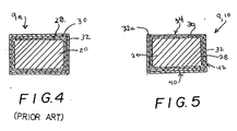
- the item shown in Fig. 4 constitutes an intermediate element 9a in the pad-producing method. That is, according to the invention, a top portion of the titanium-containing coating 32 is removed, e.g., by blasting or machining, thereby exposing the top of the titanium-free coating 30, as shown in Fig. 5 . Therefore, a top wear surface 34 of the support pad is defined by the titanium-free coating 24 (while surrounded by a very thin portion 32a of the titanium-containing coating 32 shown exaggeratedly in the figure.
- Such a pad structure can be used on drills to drill long holes in any material, but improved pad life occurs especially when machining a titanium-based workpiece. That is, by removing the titanium-containing coating from the wear surface, i.e., from the surface that contacts the workpiece, a long hole can be drilled in a titanium-based workpiece without risk of the support surfaces of the support pad being adversely affected by the titanium of the workpiece. That is, titanium, by its nature has a tendency to bond with titanium. Thus, during the drilling of a long hole utilizing a drill whose support pads have a titanium-containing coating, would result in a bonding of the wear surface's titanium with that of the workpiece. Such "chemical" wear, in addition to the normal abrasive wear, would further shorten the life of the support pad.
- the present invention provides a longer-life support pad without having to change the traditional, tried-and-tested manufacturing process described in connection with the making of the intermediate pad of Fig. 4 , except to add the step of removing the top portion of the titanium containing coating.
Landscapes
- Engineering & Computer Science (AREA)
- Mechanical Engineering (AREA)
- Chemical & Material Sciences (AREA)
- Chemical Kinetics & Catalysis (AREA)
- Materials Engineering (AREA)
- Metallurgy (AREA)
- Organic Chemistry (AREA)
- Drilling Tools (AREA)
- Earth Drilling (AREA)
Description
- The present invention relates to a support pad according to the preamble of
claim 1 for a long hole drill for metal machining with improved properties specially for STS (Single Tube System)system and for drilling tools based on the Ejector® system. The invention also relates to a drill head according to the preamble ofclaim 11 equipped with a support pad, as well as a method of manufacturing a support pad according to the preamble ofclaim 9. - Drilling in metals is divided generally in two types: long hole drilling and short hole drilling. By short hole drilling is meant generally drilling to a depth of up to 3-5 times the drill diameter.
- In short hole drilling, the demands are not great, enabling the use of simple helix drills formed either of solid cemented carbide or as solid tool steel or of tool steel provided with cemented carbide inserts.
- Long hole drilling, however, puts large demands on good chip formation, lubrication, cooling and chip transport. This is achieved through specially developed drilling systems with specially designed drilling heads fastened to a drill rod and fulfilling the above mentioned demands. The drill head may be of solid cemented carbide but is generally of tool steel provided with a number of cutting inserts of cemented carbide placed in such a way that they together form the necessary cutting edge. In the center of the head, a tough grade of insert is generally used and on the periphery a more wear resistant one. The cutting inserts are brazed or mechanically clamped. Generally the cutting inserts are brazed on small-diameter drills and mechanically secured on larger-diameter drills. In addition, the head is provided with support pads.
- Cutting inserts and support pads are made of cemented carbide with various contents of WC, Co and cubic carbides TiC, TaC, NbC depending on the application. Cutting inserts as well support pads are in addition coated with one or more wear resistant layers. Generally, the support pads are coated with a yellow layer of TiN. A long hole drill head with a geometrical configuration of inserts and support pads as outlined above and in accordance with the preambles of
claims US 6,682,275 . - It is a primary purpose of the invention to provide a support pad and a long hole drill head in combination with such a support pad wherein the useful life and strength is substantially increased, especially when drilling in a titanium-based workpiece.
- A second object of the invention is to provide an improved support head and long hole drill head having improved properties for the machining of heat resistant material, titanium based material and cast iron, as well as in the machining of nickel based alloys.
- The objects of the present invention are realised by a support pad having the features of
claim 1. - Another aspect of the invention relates to a method of manufacturing a support pad for a long hole drill head. The support pad includes a bottom support surface, a top wear surface, and a peripheral surface disposed between the wear surface and the support surface. The method comprises the steps defined in
claim 9. - A further aspect of the invention relates to a long hole drill head as defined in
claim 11. - Below follows an embodiment of the invention described with reference to the enclosed drawings.
-
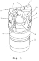
Fig 1 shows a front view of a conventional long hole drill having a support pad according to the invention. -
Fig 2 shows a perspective view obliquely from below of the long hole drill according toFig 1 . -
Fig 3 shows a perspective view of a support pad according to the invention. -
Fig. 4 shows a cross section through a prior art support pad. -
Fig. 5 is similar toFig. 4 , showing a support pad according to the present invention. - The invention relates to a
long hole drill 1 shown inFig 1 . A long hole drill according to the present invention comprises a drill head body as well as an integral connectingpart 3, which is equipped with a conventional external thread. The connectingpart 3 is generally, via said external thread, connected to a drill tube (not shown), which in its turn is carried by a suitable support device. Thedrill head 1 is in the usual way provided withcutting inserts 7. - The
drill head body 1 is in addition provided with pockets in which are mountedrespective support pads support pads chamfer part 3. In that connection thechamfers drill head body 1 takes place without there being some difference in level between thechamfers drill head 1 which said chamfers 11, 12 abut against. - The
drill head body 1 of the long hole drill according to the present invention is also provided with a firstexternal cooling channel 13 and a secondexternal cooling channel 14. These channels improve both lubrication and cooling. Saidcooling channels cooling channels drill head body 1, the cooling channels having, when seen in cross section, a soft rounded bottom with a certain radius of curvature. - In the usual way the
drill head body 1 is provided with an inside central channel 6, through which the major part of the produced the chips are discharged. - Referring to
Fig. 4 , the preferred support pad is manufactured by applying an under coating 28 entirely around a substrate comprised of abasic body 20. Thebasic body 20 comprises cemented carbide with selected contents of WC, Co and cubic carbides TiC, TaC, NbC, depending upon the application. The undercoating 28 is a titanium-containing coating of TiC or TiCN with a thickness of 2-4 µm. Applied entirely around the substrate comprised of thebasic body 20 and the undercoating 28 is a titanium-free coating 30 comprising Al2O3 having a thickness of 2-5 µm, most preferably 3-5 µm. Then, applied entirely around the substrate comprised of thebasic body 20 and thecoatings 28, 30 is a titanium-containingcoating 32 comprising TiN having a thickness of 0.5-2 µm. The coatings are deposited by conventional CVD or PVD deposition methods. The support pad shown inFig. 4 has been heretofore made and used commercially. - However, the item shown in
Fig. 4 constitutes an intermediate element 9a in the pad-producing method. That is, according to the invention, a top portion of the titanium-containingcoating 32 is removed, e.g., by blasting or machining, thereby exposing the top of the titanium-free coating 30, as shown inFig. 5 . Therefore, a top wear surface 34 of the support pad is defined by the titanium-free coating 24 (while surrounded by a verythin portion 32a of the titanium-containingcoating 32 shown exaggeratedly in the figure. - Such a pad structure can be used on drills to drill long holes in any material, but improved pad life occurs especially when machining a titanium-based workpiece. That is, by removing the titanium-containing coating from the wear surface, i.e., from the surface that contacts the workpiece, a long hole can be drilled in a titanium-based workpiece without risk of the support surfaces of the support pad being adversely affected by the titanium of the workpiece. That is, titanium, by its nature has a tendency to bond with titanium. Thus, during the drilling of a long hole utilizing a drill whose support pads have a titanium-containing coating, would result in a bonding of the wear surface's titanium with that of the workpiece. Such "chemical" wear, in addition to the normal abrasive wear, would further shorten the life of the support pad.
- Thus, the present invention provides a longer-life support pad without having to change the traditional, tried-and-tested manufacturing process described in connection with the making of the intermediate pad of
Fig. 4 , except to add the step of removing the top portion of the titanium containing coating. - Also, it will be easy for users to identify support pads made according to the invention, as well as their proper orientation on a drill, because the color of the exposed Al2O3 coating 30 at the wear surface will be different from that of the
bottom side 40 and theperipheral sides 42 of the support pad. - In the machining of a complex component made of nickel based alloy type INCO 718, long hole drilling occurred with a conventional TBT boring machine. One long hole drill head that was used that included a conventional support pad having an outer coating of TiN all around the support pad. With such a drill, drilling occurred at a speed of 80 RPM running with 15 M/min and a feed of 20 mm/min. With such machine, one component could be satisfactorily produced before the support pad had to be replaced. In contrast, when the same type of long hole drilling head was used equipped with a wear resistant coating according to the invention, it was possible to produce two such components of complex shape of Inco 718 alloy until it became necessary to replace the support pad.
Claims (11)
- A support pad (9,10) adapted for use on a long hole drill head (1), the support pad (9,10) including a bottom support surface (40), a top wear surface (34), and a peripheral surface (42) disposed between the support surface (40) and the wear surface (34), wherein the support surface (40) and the peripheral surface (42) are defined by a titanium-containing wear-resistant coating (32), characterized in that the wear surface (34) is defined by a titanium-free wear-resistant coating (30) that comprises Al2O3 and that has a different color than the titanium-containing coating (32).
- The support pad (9,10) according to claim 1 wherein the support pad (9,10) further comprises a cemented-carbide basic body (20) surrounded entirely by an under coating (28), with the titanium-free coating (30) completely surrounding the under coating (28).
- The support pad (9,10) according to claim 2 wherein the under coating (28) comprises titanium.
- The support pad (9,10) according to claim 1 wherein the titanium-free coating (30) has a thickness of 2-5 µm.
- The support pad (9,10) according to claim 4 wherein the titanium-containing coating (32) comprises TiN.
- The support pad (9,10) according to claim 5 wherein the titanium-containing coating (32) has a thickness of 0.5-2 µm.
- The support pad (9,10) according to claim 1 wherein the titanium-containing coating (32) comprises TiN.
- The support pad (9,10) according to claim 1 wherein the support pad (9,10) is configured to be indexable upon being rotated by 180 degrees.
- A method of manufacturing a support pad (9,10) for a long hole drill head (1), the support pad (9,10) including a bottom support surface (40), a top wear surface(34), and a peripheral surface (42) disposed between the wear surface (34) and the support surface (40), wherein the method is characterized in comprising the steps of:A) applying a titanium-free wear-resistant coating (30) that comprises Al2O3 completely around a substrate;B) applying a titanium-containing wear-resistant coating (32) that has a different color than the titanium-free coating (30) entirely around the titanium-free coating (30); andC) removing a top portion of the titanium-containing coating (32), wherein the bottom support surface (40) and the peripheral surface (42) are defined by the titanium-containing coating (32), and the top wear surface (34) is defined by the titanium-free coating (30) that comprises Al2O3.
- The method according to claim 9, wherein step A comprises applying a titanium-free coating (30) around a substrate comprised of a cemented carbide basic body coated entirely with a titanium-containing coating (28).
- A drill head (1) for long hole drilling comprising:a drill head body (1),cutting inserts (7) mounted in the drill head body (1), andat least one support pad (9,10) mounted to an outer periphery of the drill head body, and comprising a bottom support surface (40), a top wear surface (34), and a peripheral surface (42) disposed between the support surface (40) and the wear surface (34), wherein the support surface (40) and the peripheral surface (42) are defined by a titanium-containing wear-resistant coating (32), characterized in that the wear surface (34) is defined by a titanium-free wear-resistant coating (30) that comprises Al203 and that has a different colour than the titanium-containing coating (32).
Applications Claiming Priority (2)
| Application Number | Priority Date | Filing Date | Title |
|---|---|---|---|
| SE0302083 | 2003-07-16 | ||
| SE0302083A SE526567C2 (en) | 2003-07-16 | 2003-07-16 | Support bar for long hole drill with wear surface in different color |
Publications (3)
| Publication Number | Publication Date |
|---|---|
| EP1512477A2 EP1512477A2 (en) | 2005-03-09 |
| EP1512477A3 EP1512477A3 (en) | 2005-06-29 |
| EP1512477B1 true EP1512477B1 (en) | 2016-09-07 |
Family
ID=27765002
Family Applications (1)
| Application Number | Title | Priority Date | Filing Date |
|---|---|---|---|
| EP04016580.5A Expired - Lifetime EP1512477B1 (en) | 2003-07-16 | 2004-07-14 | Support for longhole drill |
Country Status (6)
| Country | Link |
|---|---|
| US (2) | US7207750B2 (en) |
| EP (1) | EP1512477B1 (en) |
| JP (1) | JP4689983B2 (en) |
| KR (1) | KR101139748B1 (en) |
| CN (1) | CN1575895B (en) |
| SE (1) | SE526567C2 (en) |
Cited By (3)
| Publication number | Priority date | Publication date | Assignee | Title |
|---|---|---|---|---|
| TWI762161B (en) * | 2021-01-21 | 2022-04-21 | 正河源股份有限公司 | Drilling machine chamfering tool |
| USD1009108S1 (en) | 2020-09-21 | 2023-12-26 | Kyocera Unimerco Tooling A/S | Drill |
| EP4653112A1 (en) * | 2024-05-22 | 2025-11-26 | CeramTec GmbH | Wear protection element for a carrier tool |
Families Citing this family (39)
| Publication number | Priority date | Publication date | Assignee | Title |
|---|---|---|---|---|
| US7513320B2 (en) * | 2004-12-16 | 2009-04-07 | Tdy Industries, Inc. | Cemented carbide inserts for earth-boring bits |
| US8637127B2 (en) | 2005-06-27 | 2014-01-28 | Kennametal Inc. | Composite article with coolant channels and tool fabrication method |
| JP5164838B2 (en) * | 2005-07-13 | 2013-03-21 | マパル ファブリック フュール プラツィジョンズベルクゼウグ ドクトル.クレス カーゲー | Bore cutting tool |
| US7687156B2 (en) * | 2005-08-18 | 2010-03-30 | Tdy Industries, Inc. | Composite cutting inserts and methods of making the same |
| US8021527B2 (en) * | 2005-09-14 | 2011-09-20 | Applied Materials, Inc. | Coaxial shafts for radial positioning of rotating magnetron |
| JP4797608B2 (en) * | 2005-12-02 | 2011-10-19 | 三菱マテリアル株式会社 | Surface-coated cutting insert and manufacturing method thereof |
| MX2008012771A (en) | 2006-04-27 | 2008-11-28 | Tdy Ind Inc | Modular fixed cutter earth-boring bits, modular fixed cutter earth-boring bit bodies, and related methods. |
| JP4636557B2 (en) * | 2006-07-20 | 2011-02-23 | 日立ツール株式会社 | Replaceable blade cutting tool |
| BRPI0717332A2 (en) | 2006-10-25 | 2013-10-29 | Tdy Ind Inc | ARTICLES HAVING ENHANCED RESISTANCE TO THERMAL CRACK |
| US8512882B2 (en) * | 2007-02-19 | 2013-08-20 | TDY Industries, LLC | Carbide cutting insert |
| US7846551B2 (en) | 2007-03-16 | 2010-12-07 | Tdy Industries, Inc. | Composite articles |
| JP4961246B2 (en) * | 2007-04-02 | 2012-06-27 | ユニタック株式会社 | Deep hole cutting equipment |
| CA2690230C (en) * | 2007-06-29 | 2014-06-10 | Allied Machine & Engineering Corp. | Ejector drill system |
| IL187034A0 (en) * | 2007-10-30 | 2008-02-09 | Iscar Ltd | Cutting tool |
| US7984773B2 (en) * | 2008-05-13 | 2011-07-26 | Longyear Tm, Inc. | Sonic drill bit for core sampling |
| JP2011523681A (en) | 2008-06-02 | 2011-08-18 | ティーディーワイ・インダストリーズ・インコーポレーテッド | Cemented carbide-metal alloy composite |
| US8790439B2 (en) | 2008-06-02 | 2014-07-29 | Kennametal Inc. | Composite sintered powder metal articles |
| US8322465B2 (en) | 2008-08-22 | 2012-12-04 | TDY Industries, LLC | Earth-boring bit parts including hybrid cemented carbides and methods of making the same |
| US8025112B2 (en) | 2008-08-22 | 2011-09-27 | Tdy Industries, Inc. | Earth-boring bits and other parts including cemented carbide |
| US7806204B2 (en) * | 2008-10-29 | 2010-10-05 | Longyear Tm, Inc. | Sonic drill rod with external surface features |
| JP5279561B2 (en) * | 2009-03-12 | 2013-09-04 | オーエスジー株式会社 | Single crystal diamond tool |
| US8272816B2 (en) * | 2009-05-12 | 2012-09-25 | TDY Industries, LLC | Composite cemented carbide rotary cutting tools and rotary cutting tool blanks |
| US8308096B2 (en) | 2009-07-14 | 2012-11-13 | TDY Industries, LLC | Reinforced roll and method of making same |
| US8440314B2 (en) * | 2009-08-25 | 2013-05-14 | TDY Industries, LLC | Coated cutting tools having a platinum group metal concentration gradient and related processes |
| US9643236B2 (en) * | 2009-11-11 | 2017-05-09 | Landis Solutions Llc | Thread rolling die and method of making same |
| DE202010003288U1 (en) | 2010-03-05 | 2010-08-05 | Botek Präzisionsbohrtechnik Gmbh | guide rail |
| DE102010052845B4 (en) * | 2010-11-29 | 2015-01-15 | Kennametal Inc. | Rotary cutting tool and guide insert for this |
| CN103402678A (en) * | 2011-02-28 | 2013-11-20 | 株式会社钨钛合金 | Guide pad, cutting tool body, and cutting tool |
| JP5679042B2 (en) * | 2011-02-28 | 2015-03-04 | 株式会社タンガロイ | Guide pad, cutting tool body and cutting tool |
| PL2718049T3 (en) * | 2011-06-13 | 2018-05-30 | Iscar Ltd. | Cutting tool support pad and cutting tool including such a support pad |
| US8800848B2 (en) | 2011-08-31 | 2014-08-12 | Kennametal Inc. | Methods of forming wear resistant layers on metallic surfaces |
| US9016406B2 (en) | 2011-09-22 | 2015-04-28 | Kennametal Inc. | Cutting inserts for earth-boring bits |
| WO2014104431A1 (en) * | 2012-12-28 | 2014-07-03 | 한국야금 주식회사 | Support pad for drill for processing deep hole |
| US9451969B2 (en) | 2013-05-16 | 2016-09-27 | Zimmer, Inc. | Femoral reamers having a wear indicator and related kits and methods |
| EP2862657B1 (en) | 2013-10-16 | 2016-12-21 | Sandvik Intellectual Property AB | A guide pad and a cutter head for a cutting tool |
| CN104729490B (en) * | 2015-02-04 | 2017-08-11 | 重庆交通大学 | Intelligent device for dotting |
| US20160288219A1 (en) * | 2015-04-03 | 2016-10-06 | Marcelo H. Carrascosa | Drill head |
| WO2017018422A1 (en) * | 2015-07-27 | 2017-02-02 | 株式会社タンガロイ | Cutting tool replacement member and cutting tool body |
| JP6835194B1 (en) * | 2019-12-12 | 2021-02-24 | 株式会社タンガロイ | Drilling tool |
Citations (2)
| Publication number | Priority date | Publication date | Assignee | Title |
|---|---|---|---|---|
| US20020187370A1 (en) * | 2000-07-12 | 2002-12-12 | Kazuo Yamagata | Coated cutting tool |
| US6682274B2 (en) * | 2000-10-02 | 2004-01-27 | Walter Ag | Cutting insert with wear detection |
Family Cites Families (18)
| Publication number | Priority date | Publication date | Assignee | Title |
|---|---|---|---|---|
| US3900592A (en) * | 1973-07-25 | 1975-08-19 | Airco Inc | Method for coating a substrate to provide a titanium or zirconium nitride or carbide deposit having a hardness gradient which increases outwardly from the substrate |
| DE3226799C1 (en) * | 1982-07-17 | 1990-04-19 | Mapal Fabrik für Präzisionswerkzeuge Dr.Kress KG, 7080 Aalen | One-knife reamer |
| US4984940A (en) * | 1989-03-17 | 1991-01-15 | Kennametal Inc. | Multilayer coated cemented carbide cutting insert |
| US5075181A (en) * | 1989-05-05 | 1991-12-24 | Kennametal Inc. | High hardness/high compressive stress multilayer coated tool |
| CN2078667U (en) * | 1990-11-12 | 1991-06-12 | 马尚德 | Deep hole drill for many kinds of steels |
| GB9317170D0 (en) * | 1993-08-18 | 1993-10-06 | Applied Vision Ltd | Improvements in physical vapour deposition apparatus |
| SE504331C2 (en) * | 1994-09-12 | 1997-01-13 | Sandvik Ab | Support bar for drill |
| KR100250587B1 (en) * | 1994-10-04 | 2000-04-01 | 구라우치 노리타카 | Coated hard alloy |
| JPH08168911A (en) * | 1994-12-16 | 1996-07-02 | Sanyo Special Steel Co Ltd | Bowling throwaway head |
| EP0786536B1 (en) | 1996-01-24 | 2003-05-07 | Mitsubishi Materials Corporation | Coated cutting tool |
| US5921727A (en) * | 1998-01-20 | 1999-07-13 | Cogsdill Tool Products, Inc. | Reamer with friction resistant layer and method for forming same |
| JP2000288814A (en) * | 1999-04-01 | 2000-10-17 | Sumitomo Electric Ind Ltd | Drilling tools |
| DE10017909B4 (en) * | 1999-04-13 | 2009-07-23 | Mitsubishi Materials Corp. | Coated cemented carbide cutting tool element |
| SE517446C2 (en) * | 1999-06-21 | 2002-06-04 | Sandvik Ab | Support pad / Conductor |
| SE517361C2 (en) * | 1999-06-21 | 2002-05-28 | Sandvik Ab | Deep Hole Drilling |
| SE9903090D0 (en) * | 1999-09-01 | 1999-09-01 | Sandvik Ab | Coated milling insert |
| JP4502475B2 (en) * | 2000-08-04 | 2010-07-14 | 株式会社神戸製鋼所 | Hard coating, wear-resistant member and method for producing the same |
| US6733874B2 (en) * | 2001-08-31 | 2004-05-11 | Mitsubishi Materials Corporation | Surface-coated carbide alloy cutting tool |
-
2003
- 2003-07-16 SE SE0302083A patent/SE526567C2/en not_active IP Right Cessation
-
2004
- 2004-07-08 US US10/885,873 patent/US7207750B2/en not_active Expired - Lifetime
- 2004-07-14 EP EP04016580.5A patent/EP1512477B1/en not_active Expired - Lifetime
- 2004-07-16 JP JP2004210239A patent/JP4689983B2/en not_active Expired - Fee Related
- 2004-07-16 CN CN2004100636988A patent/CN1575895B/en not_active Expired - Fee Related
- 2004-07-16 KR KR1020040055401A patent/KR101139748B1/en not_active Expired - Fee Related
-
2007
- 2007-03-05 US US11/713,607 patent/US7448832B2/en not_active Expired - Fee Related
Patent Citations (2)
| Publication number | Priority date | Publication date | Assignee | Title |
|---|---|---|---|---|
| US20020187370A1 (en) * | 2000-07-12 | 2002-12-12 | Kazuo Yamagata | Coated cutting tool |
| US6682274B2 (en) * | 2000-10-02 | 2004-01-27 | Walter Ag | Cutting insert with wear detection |
Cited By (3)
| Publication number | Priority date | Publication date | Assignee | Title |
|---|---|---|---|---|
| USD1009108S1 (en) | 2020-09-21 | 2023-12-26 | Kyocera Unimerco Tooling A/S | Drill |
| TWI762161B (en) * | 2021-01-21 | 2022-04-21 | 正河源股份有限公司 | Drilling machine chamfering tool |
| EP4653112A1 (en) * | 2024-05-22 | 2025-11-26 | CeramTec GmbH | Wear protection element for a carrier tool |
Also Published As
| Publication number | Publication date |
|---|---|
| CN1575895B (en) | 2010-08-25 |
| CN1575895A (en) | 2005-02-09 |
| SE0302083D0 (en) | 2003-07-16 |
| SE0302083L (en) | 2005-01-17 |
| US7448832B2 (en) | 2008-11-11 |
| US20050025928A1 (en) | 2005-02-03 |
| JP2005034988A (en) | 2005-02-10 |
| KR101139748B1 (en) | 2012-04-26 |
| KR20050009218A (en) | 2005-01-24 |
| EP1512477A2 (en) | 2005-03-09 |
| US7207750B2 (en) | 2007-04-24 |
| US20070154715A1 (en) | 2007-07-05 |
| SE526567C2 (en) | 2005-10-11 |
| EP1512477A3 (en) | 2005-06-29 |
| JP4689983B2 (en) | 2011-06-01 |
Similar Documents
| Publication | Publication Date | Title |
|---|---|---|
| EP1512477B1 (en) | Support for longhole drill | |
| AU615202B2 (en) | A coated cemented carbide tool | |
| US9079260B2 (en) | Polycrystalline diamond cutting tool with coated body | |
| US8080323B2 (en) | Cutting insert with a wear-resistant coating scheme exhibiting wear indication and method of making the same | |
| US6599062B1 (en) | Coated PCBN cutting inserts | |
| CN101939125B (en) | Insert for drill | |
| US10391592B2 (en) | Manufacturing of holemaking tools | |
| KR20000062268A (en) | Cubic boron nitride cutting tool | |
| EP1819469A1 (en) | Cutting insert with cutting tips anchor portions. | |
| WO2007013392A1 (en) | Edge replacing cutting tip and method for producing the same | |
| EP1842609B1 (en) | Indexable insert and method of manufacturing the same | |
| US20060045640A1 (en) | Support pads for drill heads | |
| US7736734B2 (en) | Cutting tool insert | |
| US20230173594A1 (en) | Drill and method for manufacturing machined product | |
| US6152660A (en) | Drilling tool for bores in solid material | |
| WO2021020259A1 (en) | Drill and method for manufacturing cut workpiece | |
| JP7045460B2 (en) | Manufacturing method of cutting tools and cutting products | |
| JP6825854B2 (en) | Manufacturing method of cutting tools and cutting products | |
| JP7750804B2 (en) | Drill and cutting process | |
| US20220288702A1 (en) | Rotary tool and method for manufacturing machined product | |
| WO2025074852A1 (en) | Cutting insert, cutting tool, and method for manufacturing cut workpiece | |
| WO2021117822A1 (en) | Drill and method for manufacturing cut workpiece |
Legal Events
| Date | Code | Title | Description |
|---|---|---|---|
| PUAI | Public reference made under article 153(3) epc to a published international application that has entered the european phase |
Free format text: ORIGINAL CODE: 0009012 |
|
| AK | Designated contracting states |
Kind code of ref document: A2 Designated state(s): AT BE BG CH CY CZ DE DK EE ES FI FR GB GR HU IE IT LI LU MC NL PL PT RO SE SI SK TR |
|
| AX | Request for extension of the european patent |
Extension state: AL HR LT LV MK |
|
| PUAL | Search report despatched |
Free format text: ORIGINAL CODE: 0009013 |
|
| AK | Designated contracting states |
Kind code of ref document: A3 Designated state(s): AT BE BG CH CY CZ DE DK EE ES FI FR GB GR HU IE IT LI LU MC NL PL PT RO SE SI SK TR |
|
| AX | Request for extension of the european patent |
Extension state: AL HR LT LV MK |
|
| RAP1 | Party data changed (applicant data changed or rights of an application transferred) |
Owner name: SANDVIK INTELLECTUAL PROPERTY HB |
|
| RAP1 | Party data changed (applicant data changed or rights of an application transferred) |
Owner name: SANDVIK INTELLECTUAL PROPERTY AB |
|
| 17P | Request for examination filed |
Effective date: 20051014 |
|
| AKX | Designation fees paid |
Designated state(s): AT BE BG CH CY CZ DE DK EE ES FI FR GB GR HU IE IT LI LU MC NL PL PT RO SE SI SK TR |
|
| 17Q | First examination report despatched |
Effective date: 20070112 |
|
| GRAP | Despatch of communication of intention to grant a patent |
Free format text: ORIGINAL CODE: EPIDOSNIGR1 |
|
| INTG | Intention to grant announced |
Effective date: 20160420 |
|
| GRAS | Grant fee paid |
Free format text: ORIGINAL CODE: EPIDOSNIGR3 |
|
| GRAA | (expected) grant |
Free format text: ORIGINAL CODE: 0009210 |
|
| AK | Designated contracting states |
Kind code of ref document: B1 Designated state(s): AT BE BG CH CY CZ DE DK EE ES FI FR GB GR HU IE IT LI LU MC NL PL PT RO SE SI SK TR |
|
| REG | Reference to a national code |
Ref country code: GB Ref legal event code: FG4D |
|
| REG | Reference to a national code |
Ref country code: CH Ref legal event code: EP |
|
| REG | Reference to a national code |
Ref country code: IE Ref legal event code: FG4D |
|
| REG | Reference to a national code |
Ref country code: DE Ref legal event code: R096 Ref document number: 602004049895 Country of ref document: DE |
|
| REG | Reference to a national code |
Ref country code: AT Ref legal event code: REF Ref document number: 826392 Country of ref document: AT Kind code of ref document: T Effective date: 20161015 |
|
| REG | Reference to a national code |
Ref country code: NL Ref legal event code: MP Effective date: 20160907 |
|
| PG25 | Lapsed in a contracting state [announced via postgrant information from national office to epo] |
Ref country code: FI Free format text: LAPSE BECAUSE OF FAILURE TO SUBMIT A TRANSLATION OF THE DESCRIPTION OR TO PAY THE FEE WITHIN THE PRESCRIBED TIME-LIMIT Effective date: 20160907 |
|
| REG | Reference to a national code |
Ref country code: AT Ref legal event code: MK05 Ref document number: 826392 Country of ref document: AT Kind code of ref document: T Effective date: 20160907 |
|
| PG25 | Lapsed in a contracting state [announced via postgrant information from national office to epo] |
Ref country code: GR Free format text: LAPSE BECAUSE OF FAILURE TO SUBMIT A TRANSLATION OF THE DESCRIPTION OR TO PAY THE FEE WITHIN THE PRESCRIBED TIME-LIMIT Effective date: 20161208 Ref country code: SE Free format text: LAPSE BECAUSE OF FAILURE TO SUBMIT A TRANSLATION OF THE DESCRIPTION OR TO PAY THE FEE WITHIN THE PRESCRIBED TIME-LIMIT Effective date: 20160907 Ref country code: NL Free format text: LAPSE BECAUSE OF FAILURE TO SUBMIT A TRANSLATION OF THE DESCRIPTION OR TO PAY THE FEE WITHIN THE PRESCRIBED TIME-LIMIT Effective date: 20160907 Ref country code: ES Free format text: LAPSE BECAUSE OF FAILURE TO SUBMIT A TRANSLATION OF THE DESCRIPTION OR TO PAY THE FEE WITHIN THE PRESCRIBED TIME-LIMIT Effective date: 20160907 |
|
| PG25 | Lapsed in a contracting state [announced via postgrant information from national office to epo] |
Ref country code: EE Free format text: LAPSE BECAUSE OF FAILURE TO SUBMIT A TRANSLATION OF THE DESCRIPTION OR TO PAY THE FEE WITHIN THE PRESCRIBED TIME-LIMIT Effective date: 20160907 Ref country code: RO Free format text: LAPSE BECAUSE OF FAILURE TO SUBMIT A TRANSLATION OF THE DESCRIPTION OR TO PAY THE FEE WITHIN THE PRESCRIBED TIME-LIMIT Effective date: 20160907 |
|
| PG25 | Lapsed in a contracting state [announced via postgrant information from national office to epo] |
Ref country code: CZ Free format text: LAPSE BECAUSE OF FAILURE TO SUBMIT A TRANSLATION OF THE DESCRIPTION OR TO PAY THE FEE WITHIN THE PRESCRIBED TIME-LIMIT Effective date: 20160907 Ref country code: PT Free format text: LAPSE BECAUSE OF FAILURE TO SUBMIT A TRANSLATION OF THE DESCRIPTION OR TO PAY THE FEE WITHIN THE PRESCRIBED TIME-LIMIT Effective date: 20170109 Ref country code: AT Free format text: LAPSE BECAUSE OF FAILURE TO SUBMIT A TRANSLATION OF THE DESCRIPTION OR TO PAY THE FEE WITHIN THE PRESCRIBED TIME-LIMIT Effective date: 20160907 Ref country code: PL Free format text: LAPSE BECAUSE OF FAILURE TO SUBMIT A TRANSLATION OF THE DESCRIPTION OR TO PAY THE FEE WITHIN THE PRESCRIBED TIME-LIMIT Effective date: 20160907 Ref country code: SK Free format text: LAPSE BECAUSE OF FAILURE TO SUBMIT A TRANSLATION OF THE DESCRIPTION OR TO PAY THE FEE WITHIN THE PRESCRIBED TIME-LIMIT Effective date: 20160907 Ref country code: BG Free format text: LAPSE BECAUSE OF FAILURE TO SUBMIT A TRANSLATION OF THE DESCRIPTION OR TO PAY THE FEE WITHIN THE PRESCRIBED TIME-LIMIT Effective date: 20161207 Ref country code: BE Free format text: LAPSE BECAUSE OF FAILURE TO SUBMIT A TRANSLATION OF THE DESCRIPTION OR TO PAY THE FEE WITHIN THE PRESCRIBED TIME-LIMIT Effective date: 20160907 |
|
| REG | Reference to a national code |
Ref country code: DE Ref legal event code: R097 Ref document number: 602004049895 Country of ref document: DE |
|
| PLBE | No opposition filed within time limit |
Free format text: ORIGINAL CODE: 0009261 |
|
| STAA | Information on the status of an ep patent application or granted ep patent |
Free format text: STATUS: NO OPPOSITION FILED WITHIN TIME LIMIT |
|
| PG25 | Lapsed in a contracting state [announced via postgrant information from national office to epo] |
Ref country code: DK Free format text: LAPSE BECAUSE OF FAILURE TO SUBMIT A TRANSLATION OF THE DESCRIPTION OR TO PAY THE FEE WITHIN THE PRESCRIBED TIME-LIMIT Effective date: 20160907 |
|
| 26N | No opposition filed |
Effective date: 20170608 |
|
| PG25 | Lapsed in a contracting state [announced via postgrant information from national office to epo] |
Ref country code: SI Free format text: LAPSE BECAUSE OF FAILURE TO SUBMIT A TRANSLATION OF THE DESCRIPTION OR TO PAY THE FEE WITHIN THE PRESCRIBED TIME-LIMIT Effective date: 20160907 |
|
| REG | Reference to a national code |
Ref country code: DE Ref legal event code: R119 Ref document number: 602004049895 Country of ref document: DE |
|
| REG | Reference to a national code |
Ref country code: CH Ref legal event code: PL |
|
| GBPC | Gb: european patent ceased through non-payment of renewal fee |
Effective date: 20170714 |
|
| REG | Reference to a national code |
Ref country code: IE Ref legal event code: MM4A |
|
| REG | Reference to a national code |
Ref country code: FR Ref legal event code: ST Effective date: 20180330 |
|
| PG25 | Lapsed in a contracting state [announced via postgrant information from national office to epo] |
Ref country code: DE Free format text: LAPSE BECAUSE OF NON-PAYMENT OF DUE FEES Effective date: 20180201 Ref country code: IE Free format text: LAPSE BECAUSE OF NON-PAYMENT OF DUE FEES Effective date: 20170714 Ref country code: LI Free format text: LAPSE BECAUSE OF NON-PAYMENT OF DUE FEES Effective date: 20170731 Ref country code: GB Free format text: LAPSE BECAUSE OF NON-PAYMENT OF DUE FEES Effective date: 20170714 Ref country code: CH Free format text: LAPSE BECAUSE OF NON-PAYMENT OF DUE FEES Effective date: 20170731 |
|
| PG25 | Lapsed in a contracting state [announced via postgrant information from national office to epo] |
Ref country code: FR Free format text: LAPSE BECAUSE OF NON-PAYMENT OF DUE FEES Effective date: 20170731 |
|
| PG25 | Lapsed in a contracting state [announced via postgrant information from national office to epo] |
Ref country code: LU Free format text: LAPSE BECAUSE OF NON-PAYMENT OF DUE FEES Effective date: 20170714 |
|
| PGFP | Annual fee paid to national office [announced via postgrant information from national office to epo] |
Ref country code: IT Payment date: 20180713 Year of fee payment: 15 |
|
| PG25 | Lapsed in a contracting state [announced via postgrant information from national office to epo] |
Ref country code: HU Free format text: LAPSE BECAUSE OF FAILURE TO SUBMIT A TRANSLATION OF THE DESCRIPTION OR TO PAY THE FEE WITHIN THE PRESCRIBED TIME-LIMIT; INVALID AB INITIO Effective date: 20040714 Ref country code: MC Free format text: LAPSE BECAUSE OF FAILURE TO SUBMIT A TRANSLATION OF THE DESCRIPTION OR TO PAY THE FEE WITHIN THE PRESCRIBED TIME-LIMIT Effective date: 20160907 |
|
| PG25 | Lapsed in a contracting state [announced via postgrant information from national office to epo] |
Ref country code: CY Free format text: LAPSE BECAUSE OF NON-PAYMENT OF DUE FEES Effective date: 20160907 |
|
| PG25 | Lapsed in a contracting state [announced via postgrant information from national office to epo] |
Ref country code: TR Free format text: LAPSE BECAUSE OF FAILURE TO SUBMIT A TRANSLATION OF THE DESCRIPTION OR TO PAY THE FEE WITHIN THE PRESCRIBED TIME-LIMIT Effective date: 20160907 |
|
| PG25 | Lapsed in a contracting state [announced via postgrant information from national office to epo] |
Ref country code: IT Free format text: LAPSE BECAUSE OF NON-PAYMENT OF DUE FEES Effective date: 20190714 |