EP1512155B1 - Procede et dispositif pour eliminer une gaine d'elements combustibles dans une centrale nucleaire a reacteur a eau bouillante - Google Patents
Procede et dispositif pour eliminer une gaine d'elements combustibles dans une centrale nucleaire a reacteur a eau bouillante Download PDFInfo
- Publication number
- EP1512155B1 EP1512155B1 EP03759894A EP03759894A EP1512155B1 EP 1512155 B1 EP1512155 B1 EP 1512155B1 EP 03759894 A EP03759894 A EP 03759894A EP 03759894 A EP03759894 A EP 03759894A EP 1512155 B1 EP1512155 B1 EP 1512155B1
- Authority
- EP
- European Patent Office
- Prior art keywords
- fuel assembly
- assembly box
- carrier structure
- stabilized
- fuel
- Prior art date
- Legal status (The legal status is an assumption and is not a legal conclusion. Google has not performed a legal analysis and makes no representation as to the accuracy of the status listed.)
- Expired - Lifetime
Links
- 239000000446 fuel Substances 0.000 title claims description 48
- 238000000034 method Methods 0.000 title claims description 19
- XLYOFNOQVPJJNP-UHFFFAOYSA-N water Substances O XLYOFNOQVPJJNP-UHFFFAOYSA-N 0.000 title claims description 8
- 238000009835 boiling Methods 0.000 title description 5
- 238000005192 partition Methods 0.000 claims description 7
- 239000008358 core component Substances 0.000 claims description 3
- 230000001143 conditioned effect Effects 0.000 description 3
- 125000006850 spacer group Chemical group 0.000 description 3
- 239000000306 component Substances 0.000 description 2
- 230000003750 conditioning effect Effects 0.000 description 1
- 239000000498 cooling water Substances 0.000 description 1
- 238000000354 decomposition reaction Methods 0.000 description 1
- 238000003780 insertion Methods 0.000 description 1
- 230000037431 insertion Effects 0.000 description 1
- 230000002452 interceptive effect Effects 0.000 description 1
- 238000002360 preparation method Methods 0.000 description 1
- 238000003825 pressing Methods 0.000 description 1
- 230000005855 radiation Effects 0.000 description 1
- 239000002915 spent fuel radioactive waste Substances 0.000 description 1
- 230000003319 supportive effect Effects 0.000 description 1
Images

Classifications
-
- G—PHYSICS
- G21—NUCLEAR PHYSICS; NUCLEAR ENGINEERING
- G21F—PROTECTION AGAINST X-RADIATION, GAMMA RADIATION, CORPUSCULAR RADIATION OR PARTICLE BOMBARDMENT; TREATING RADIOACTIVELY CONTAMINATED MATERIAL; DECONTAMINATION ARRANGEMENTS THEREFOR
- G21F5/00—Transportable or portable shielded containers
- G21F5/005—Containers for solid radioactive wastes, e.g. for ultimate disposal
Definitions
- the invention relates to a method for disposing of a fuel box.
- the invention relates to a method and apparatus for disposing of radioactively contaminated parts of a boiling water reactor plant.
- the wall 2 of such a fuel element box 4 encloses a substantially rectangular cavity 6.
- the fuel box 4 is open at its ends and is only provided on a front side at opposite corners with support struts 8a, which for fixing the fuel channel 4 on serve a fuel element head, not shown in the figure.
- the fuel channel 4 is provided in its lower region with further elements, in the example nubs 8b and outer plates 8c, which are specific to the type of box shown by way of example. In the conditioning of such a fuel element box this is usually pressed and then cut into small pieces. However, such a procedure is expensive.
- the invention is based on the object to provide a method for disposing of a fuel assembly of a boiling water reactor system, which is simplified compared to the procedure mentioned in the prior art.
- the invention is based on the object to provide a method for disposing of radioactively contaminated parts of a boiling water reactor system and an apparatus for performing this method.
- the first object is achieved according to the invention with a method having the features of claim 1.
- the fuel assembly is stabilized with a preassembled support structure by inserting the support structure into the fuel assembly.
- the fuel channel box is closed on one of its end faces by means of a base plate arranged on the support structure and serving as a base.
- the fuel assembly is not destroyed but provided with one or more supportive components that give it a higher strength or stability.
- a prepared in this way for the disposal or conditioned fuel assembly can also also as a transport container for other parts to be disposed of and correspondingly conditioned parts, in particular for core components or for small-volume so-called core scrap to be used.
- the fuel assembly is provided with a carrying handle. Thereby, it can be handled in the same way with the same facilities as they are provided for the handling of the fuel assembly.
- the object is achieved according to the invention with the features of claim 3. Since the stabilized fuel assembly is used as a transport container for more radioactively contaminated parts, its particularly cost-effective disposal is possible together with the core scrap.
- the leaves are separated from a control element to be disposed and introduced into the stabilized fuel assembly. Since the longitudinal and transverse expansions of the leaves of a control largely correspond to those of a fuel box these can be accommodated in a fuel box extremely space-saving, which can accommodate the leaves of three controls in this way.
- the support structure divides the fuel assembly with an internal partition in at least two sub-areas, which is supported during insertion of the leaves in one of the sub-areas. As a result, the filling of the fuel channel is facilitated.
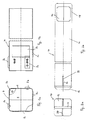
- the support structure 10 comprises a base plate 12 which carries a partition plate 14 extending perpendicularly to the flat side of the base plate and in particular is welded thereto.
- the partition plate 14 has a longitudinal extent which is greater than the longitudinal extent of the fuel channel 4 and is provided at its side facing away from the base plate 12 free end with a recess 16 so that a carrying handle 18 is formed.
- a spacer plate 20 is fixed on this, which passes through the provided in this area with a slot 22 partition plate 14.
- FIGS. 3a, b For this purpose, this is introduced from the bottom side into the empty fuel element box 4 until the base plate 12 closes the empty fuel element box 4 and forms a bottom. The carrying handle 18 then protrudes beyond the fuel channel 4. It can also be seen in the figure that the fuel element box 4 is subdivided by the separating plate 14 into two subregions 42, 44.
- FIGS. 4a, b are in the stabilized with the support structure 10 fuel assembly 40 control rod blades 24 inserted, which have been separated in a previous step from to be disposed of tax bars and of which in FIG. 4b a halved by the previous decomposition bracket 26 is shown a carrying handle.
- the spacer plate 20 serves to support the control rod blades 24 so that the space used to hold the control blade blades 24 is free from interfering internals located at the bottom of the fuel box 4. At the same time four sub-chambers 46 are formed below the control blades 24, which can be used to hold small-volume core scrap.
Landscapes
- Physics & Mathematics (AREA)
- Engineering & Computer Science (AREA)
- General Engineering & Computer Science (AREA)
- High Energy & Nuclear Physics (AREA)
- Structure Of Emergency Protection For Nuclear Reactors (AREA)
- Monitoring And Testing Of Nuclear Reactors (AREA)
- Processing Of Solid Wastes (AREA)
Claims (8)
- Procédé pour évacuer un boitier canal d'assemblage combustible (4) d'une centrale de réacteur à eau bouillante, dans lequel le boitier canal d'assemblage combustible (4) est stabilisé avec une structure portante (10) préfabriquée, en insérant la structure portante (10) dans le boitier canal d'assemblage combustible (4) et dans lequel un côté frontal du boitier canal d'assemblage combustible (4) est obturé à l'aide d'une plaque de base (12) disposée sur la structure portante (10) et servant de fond.
- Procédé selon la revendication 1, dans lequel la structure portante (10) est pourvue d'une poignée de transport (18).
- Procédé pour évacuer des pièces contaminées radioactives d'une centrale de réacteur à eau bouillante, notamment des pièces encastrées dans le coeur du réacteur, dans lequel un boitier canal (40) stabilisé conformément à une des revendications précédentes est utilisé comme contenant de transport.
- Procédé selon la revendication 3, dans lequel les lames de barre de commande (24) sont séparées d'une barre de commande à éliminer et sont insérées dans le boitier canal d'assemblage combustible (40) stabilisé.
- Procédé selon la revendication 4, dans lequel la structure portante divise avec une paroi de séparation (14) intérieure le boitier canal d'assemblage combustible (40) stabilisé en au moins deux zones partielles (42, 44), laquelle est soutenue lors de l'insertion des lames dans une des zones partielles (42, 44).
- Dispositif pour évacuer des pièces contaminées radioactives d'une centrale de réacteur à eau bouillante, notamment des pièces encastrées dans le coeur du réacteur, comportant un boitier canal d'assemblage combustible (40), qui est stabilisé avec une structure portante (10) préfabriquée, insérée dans le boitier canal de combustible (40) et sert de contenant de transport, dans lequel la structure portante (10) comprend une plaque de base (12), qui obture d'un côté la caisse de combustible (4).
- Dispositif selon la revendication 6, dans lequel la structure portante (10) est pourvue d'une poignée de transport (18).
- Dispositif selon la revendication 6 ou 7, dans lequel est disposée au moins une plaque de séparation (14) disposée perpendiculairement à la plaque de base (12) de la structure portante (10), laquelle divise l'espace interne du boitier canal d'assemblage combustible (40) stabilisé en au moins deux zones partielles (42, 44).
Applications Claiming Priority (3)
| Application Number | Priority Date | Filing Date | Title |
|---|---|---|---|
| DE10226245A DE10226245A1 (de) | 2002-06-13 | 2002-06-13 | Verfahren und Vorrichtung zum Entsorgen eines Brennelementkastens Entsorgen einer Siedewasserreaktoranlage |
| DE10226245 | 2002-06-13 | ||
| PCT/EP2003/005339 WO2003107356A1 (fr) | 2002-06-13 | 2003-05-22 | Procede et dispositif pour eliminer une gaine d'elements combustibles dans une centrale nucleaire a reacteur a eau bouillante |
Publications (2)
| Publication Number | Publication Date |
|---|---|
| EP1512155A1 EP1512155A1 (fr) | 2005-03-09 |
| EP1512155B1 true EP1512155B1 (fr) | 2009-04-01 |
Family
ID=29719014
Family Applications (1)
| Application Number | Title | Priority Date | Filing Date |
|---|---|---|---|
| EP03759894A Expired - Lifetime EP1512155B1 (fr) | 2002-06-13 | 2003-05-22 | Procede et dispositif pour eliminer une gaine d'elements combustibles dans une centrale nucleaire a reacteur a eau bouillante |
Country Status (6)
| Country | Link |
|---|---|
| EP (1) | EP1512155B1 (fr) |
| JP (1) | JP2005534003A (fr) |
| DE (2) | DE10226245A1 (fr) |
| ES (1) | ES2322648T3 (fr) |
| TW (1) | TWI220992B (fr) |
| WO (1) | WO2003107356A1 (fr) |
Families Citing this family (1)
| Publication number | Priority date | Publication date | Assignee | Title |
|---|---|---|---|---|
| JP5781265B2 (ja) * | 2009-07-31 | 2015-09-16 | 三菱重工業株式会社 | 燃料集合体の輸送容器 |
Family Cites Families (4)
| Publication number | Priority date | Publication date | Assignee | Title |
|---|---|---|---|---|
| US5629964A (en) * | 1994-03-11 | 1997-05-13 | Roberts; Paul | Neutron absorbing apparatus |
| DE19728978A1 (de) * | 1997-07-07 | 1999-01-14 | Siemens Ag | Behälter für mehrere gebrauchte Brennelemente eines Kernreaktors |
| DE29912810U1 (de) * | 1999-07-22 | 2000-11-23 | Siemens AG, 80333 München | Brennelementkasten mit Anschlag für Hebewerkzeug |
| DE19947120C2 (de) * | 1999-09-30 | 2002-02-28 | Framatome Anp Gmbh | Verfahren zur Vorbereitung eines Brennelements für die Endlagerung und vorbereitetes Brennelement |
-
2002
- 2002-06-13 DE DE10226245A patent/DE10226245A1/de not_active Withdrawn
-
2003
- 2003-05-22 EP EP03759894A patent/EP1512155B1/fr not_active Expired - Lifetime
- 2003-05-22 WO PCT/EP2003/005339 patent/WO2003107356A1/fr active Application Filing
- 2003-05-22 JP JP2004514086A patent/JP2005534003A/ja active Pending
- 2003-05-22 ES ES03759894T patent/ES2322648T3/es not_active Expired - Lifetime
- 2003-05-22 DE DE50311371T patent/DE50311371D1/de not_active Expired - Lifetime
- 2003-06-06 TW TW092115357A patent/TWI220992B/zh not_active IP Right Cessation
Also Published As
| Publication number | Publication date |
|---|---|
| DE50311371D1 (de) | 2009-05-14 |
| TWI220992B (en) | 2004-09-11 |
| WO2003107356A1 (fr) | 2003-12-24 |
| ES2322648T3 (es) | 2009-06-24 |
| EP1512155A1 (fr) | 2005-03-09 |
| JP2005534003A (ja) | 2005-11-10 |
| TW200402740A (en) | 2004-02-16 |
| DE10226245A1 (de) | 2004-01-08 |
Similar Documents
| Publication | Publication Date | Title |
|---|---|---|
| DE69601690T2 (de) | Einrichtung und Verfahren zum gemeinsamen Lagern von Kernbrennstabbündeln und Steuerstäben | |
| DE69007338T2 (de) | Kernreaktorbrennstabbündel mit einer Vorrichtung zum Auffangen von Teilchen, die sich im Reaktorkühlwasser befinden. | |
| CH686819A5 (de) | Werkzeug fuer eine Stanzpresse mit einer Laser-Schweissanlage. | |
| EP1512155B1 (fr) | Procede et dispositif pour eliminer une gaine d'elements combustibles dans une centrale nucleaire a reacteur a eau bouillante | |
| CH618040A5 (en) | Device for the ultimate disposal of radioactive waste substances | |
| DE202017005797U1 (de) | Tragende Struktur für einen Multicopter | |
| EP2017853B1 (fr) | Procédé de démantèlement d'une centrale nucléaire | |
| EP1439547B1 (fr) | Conteneur de transport et/ou de stockage pour éléments de combustible épuisés, éléments de combustible endommagés et/ou des barreaux de combustible d'un élément de combustible endommagés | |
| DD222720A5 (de) | Fluessigkeitsgekuehlter kernreaktor, insbesondere siedewasserreaktor | |
| EP1989715B1 (fr) | Element de combustible pour reacteur a eau legere | |
| DE10313792B4 (de) | Bearbeitungsstation zur Bearbeitung eines Werkstücks | |
| DE4017987C2 (fr) | ||
| DE102019103202A1 (de) | Verfahren und Vorrichtung samt Montagewerkzeug sowie Computerprogramm zum Herstellen eines Zwischenwandgitters | |
| DE19628362C1 (de) | Verfahren zum Transport und zur Lagerung von abgebrannten Brennelementen und Neutronenabsorber für die Durchführung des Verfahrens | |
| DE3830067C1 (fr) | ||
| DE3529312A1 (de) | Verfahren zum enthuellen bzw. auseinandernehmen von bestrahlten kernbrennstoffelementen | |
| EP4272227A1 (fr) | Renforcement d'ensembles combustibles de centrales nucléaires | |
| EP0151306A2 (fr) | Procédé pour maintenir le régime sous-critique des éléments de combustible | |
| DE2445984A1 (de) | Verfahren zur brennstoffversorgung von kernreaktoren und brennelement dafuer | |
| DE10137284B4 (de) | Verfahren zum Zerlegen eines verfahrenstechnischen Apparates | |
| DE102014116224A1 (de) | Gitterrost zur industriellen Warmbehandlung | |
| DE2935043A1 (de) | Halterung fuer eine vielzahl von langgestreckten einzelteilen | |
| DE7622329U1 (de) | Vorrichtung fuer die endlagerung von nach der aktivitaet klassierten radioaktiven abfallstoffen | |
| DE19937670A1 (de) | Verfahren und Vorrichtung zur Handhabung eines Brennelement-Lagergestells | |
| DE10348439B4 (de) | Stanzvorrichtung für Verpackungsfolien |
Legal Events
| Date | Code | Title | Description |
|---|---|---|---|
| PUAI | Public reference made under article 153(3) epc to a published international application that has entered the european phase |
Free format text: ORIGINAL CODE: 0009012 |
|
| 17P | Request for examination filed |
Effective date: 20041009 |
|
| AK | Designated contracting states |
Kind code of ref document: A1 Designated state(s): AT BE BG CH CY CZ DE DK EE ES FI FR GB GR HU IE IT LI LU MC NL PT RO SE SI SK TR |
|
| RBV | Designated contracting states (corrected) |
Designated state(s): DE ES FI SE |
|
| RAP1 | Party data changed (applicant data changed or rights of an application transferred) |
Owner name: AREVA NP GMBH |
|
| RAP1 | Party data changed (applicant data changed or rights of an application transferred) |
Owner name: AREVA NP GMBH |
|
| GRAP | Despatch of communication of intention to grant a patent |
Free format text: ORIGINAL CODE: EPIDOSNIGR1 |
|
| GRAS | Grant fee paid |
Free format text: ORIGINAL CODE: EPIDOSNIGR3 |
|
| GRAA | (expected) grant |
Free format text: ORIGINAL CODE: 0009210 |
|
| AK | Designated contracting states |
Kind code of ref document: B1 Designated state(s): DE ES FI SE |
|
| REF | Corresponds to: |
Ref document number: 50311371 Country of ref document: DE Date of ref document: 20090514 Kind code of ref document: P |
|
| REG | Reference to a national code |
Ref country code: ES Ref legal event code: FG2A Ref document number: 2322648 Country of ref document: ES Kind code of ref document: T3 |
|
| REG | Reference to a national code |
Ref country code: SE Ref legal event code: TRGR |
|
| PLBE | No opposition filed within time limit |
Free format text: ORIGINAL CODE: 0009261 |
|
| STAA | Information on the status of an ep patent application or granted ep patent |
Free format text: STATUS: NO OPPOSITION FILED WITHIN TIME LIMIT |
|
| 26N | No opposition filed |
Effective date: 20100105 |
|
| PGFP | Annual fee paid to national office [announced via postgrant information from national office to epo] |
Ref country code: ES Payment date: 20110524 Year of fee payment: 9 Ref country code: SE Payment date: 20110523 Year of fee payment: 9 |
|
| PGFP | Annual fee paid to national office [announced via postgrant information from national office to epo] |
Ref country code: FI Payment date: 20110520 Year of fee payment: 9 |
|
| PGFP | Annual fee paid to national office [announced via postgrant information from national office to epo] |
Ref country code: DE Payment date: 20110720 Year of fee payment: 9 |
|
| REG | Reference to a national code |
Ref country code: SE Ref legal event code: EUG |
|
| PG25 | Lapsed in a contracting state [announced via postgrant information from national office to epo] |
Ref country code: FI Free format text: LAPSE BECAUSE OF NON-PAYMENT OF DUE FEES Effective date: 20120522 |
|
| PG25 | Lapsed in a contracting state [announced via postgrant information from national office to epo] |
Ref country code: SE Free format text: LAPSE BECAUSE OF NON-PAYMENT OF DUE FEES Effective date: 20120523 |
|
| REG | Reference to a national code |
Ref country code: DE Ref legal event code: R119 Ref document number: 50311371 Country of ref document: DE Effective date: 20121201 |
|
| PG25 | Lapsed in a contracting state [announced via postgrant information from national office to epo] |
Ref country code: DE Free format text: LAPSE BECAUSE OF NON-PAYMENT OF DUE FEES Effective date: 20121201 |
|
| REG | Reference to a national code |
Ref country code: ES Ref legal event code: FD2A Effective date: 20131022 |
|
| PG25 | Lapsed in a contracting state [announced via postgrant information from national office to epo] |
Ref country code: ES Free format text: LAPSE BECAUSE OF NON-PAYMENT OF DUE FEES Effective date: 20120523 |