EP1511909B9 - Multipurpose seal with lock and method of manufacturing a multipurpose seal - Google Patents
Multipurpose seal with lock and method of manufacturing a multipurpose seal Download PDFInfo
- Publication number
- EP1511909B9 EP1511909B9 EP20030730200 EP03730200A EP1511909B9 EP 1511909 B9 EP1511909 B9 EP 1511909B9 EP 20030730200 EP20030730200 EP 20030730200 EP 03730200 A EP03730200 A EP 03730200A EP 1511909 B9 EP1511909 B9 EP 1511909B9
- Authority
- EP
- European Patent Office
- Prior art keywords
- housing
- electronic component
- seal
- lock
- cylinder
- Prior art date
- Legal status (The legal status is an assumption and is not a legal conclusion. Google has not performed a legal analysis and makes no representation as to the accuracy of the status listed.)
- Expired - Lifetime
Links
- 238000004519 manufacturing process Methods 0.000 title claims description 5
- 238000000034 method Methods 0.000 claims description 11
- 238000013500 data storage Methods 0.000 claims description 10
- 241001465754 Metazoa Species 0.000 claims description 6
- 238000011144 upstream manufacturing Methods 0.000 claims description 3
- FGUUSXIOTUKUDN-IBGZPJMESA-N C1(=CC=CC=C1)N1C2=C(NC([C@H](C1)NC=1OC(=NN=1)C1=CC=CC=C1)=O)C=CC=C2 Chemical compound C1(=CC=CC=C1)N1C2=C(NC([C@H](C1)NC=1OC(=NN=1)C1=CC=CC=C1)=O)C=CC=C2 FGUUSXIOTUKUDN-IBGZPJMESA-N 0.000 claims description 2
- 238000005553 drilling Methods 0.000 claims description 2
- 238000003754 machining Methods 0.000 claims description 2
- 230000006378 damage Effects 0.000 description 5
- 238000007789 sealing Methods 0.000 description 5
- 238000003860 storage Methods 0.000 description 4
- 239000000853 adhesive Substances 0.000 description 3
- 230000001070 adhesive effect Effects 0.000 description 3
- 239000011521 glass Substances 0.000 description 3
- 230000006870 function Effects 0.000 description 2
- CNQCVBJFEGMYDW-UHFFFAOYSA-N lawrencium atom Chemical compound [Lr] CNQCVBJFEGMYDW-UHFFFAOYSA-N 0.000 description 2
- 239000002184 metal Substances 0.000 description 2
- 229910000831 Steel Inorganic materials 0.000 description 1
- 230000004913 activation Effects 0.000 description 1
- 238000013475 authorization Methods 0.000 description 1
- 230000005540 biological transmission Effects 0.000 description 1
- 230000000903 blocking effect Effects 0.000 description 1
- 238000013461 design Methods 0.000 description 1
- 238000005516 engineering process Methods 0.000 description 1
- 238000009434 installation Methods 0.000 description 1
- 239000000463 material Substances 0.000 description 1
- 239000011824 nuclear material Substances 0.000 description 1
- 230000003287 optical effect Effects 0.000 description 1
- 230000001681 protective effect Effects 0.000 description 1
- 125000006850 spacer group Chemical group 0.000 description 1
- 239000010959 steel Substances 0.000 description 1
- 239000000126 substance Substances 0.000 description 1
- 238000013519 translation Methods 0.000 description 1
- 238000012795 verification Methods 0.000 description 1
- 238000011179 visual inspection Methods 0.000 description 1
- 239000002699 waste material Substances 0.000 description 1
- 229910000859 α-Fe Inorganic materials 0.000 description 1
Images

Classifications
-
- E—FIXED CONSTRUCTIONS
- E05—LOCKS; KEYS; WINDOW OR DOOR FITTINGS; SAFES
- E05B—LOCKS; ACCESSORIES THEREFOR; HANDCUFFS
- E05B39/00—Locks giving indication of authorised or unauthorised unlocking
- E05B39/02—Locks giving indication of authorised or unauthorised unlocking with destructible seal closures or paper closures
-
- Y—GENERAL TAGGING OF NEW TECHNOLOGICAL DEVELOPMENTS; GENERAL TAGGING OF CROSS-SECTIONAL TECHNOLOGIES SPANNING OVER SEVERAL SECTIONS OF THE IPC; TECHNICAL SUBJECTS COVERED BY FORMER USPC CROSS-REFERENCE ART COLLECTIONS [XRACs] AND DIGESTS
- Y10—TECHNICAL SUBJECTS COVERED BY FORMER USPC
- Y10T—TECHNICAL SUBJECTS COVERED BY FORMER US CLASSIFICATION
- Y10T70/00—Locks
- Y10T70/40—Portable
- Y10T70/413—Padlocks
- Y10T70/437—Key-controlled
- Y10T70/446—Rigid shackle
- Y10T70/452—Sliding
- Y10T70/459—Both legs engaged
-
- Y—GENERAL TAGGING OF NEW TECHNOLOGICAL DEVELOPMENTS; GENERAL TAGGING OF CROSS-SECTIONAL TECHNOLOGIES SPANNING OVER SEVERAL SECTIONS OF THE IPC; TECHNICAL SUBJECTS COVERED BY FORMER USPC CROSS-REFERENCE ART COLLECTIONS [XRACs] AND DIGESTS
- Y10—TECHNICAL SUBJECTS COVERED BY FORMER USPC
- Y10T—TECHNICAL SUBJECTS COVERED BY FORMER US CLASSIFICATION
- Y10T70/00—Locks
- Y10T70/40—Portable
- Y10T70/413—Padlocks
- Y10T70/437—Key-controlled
- Y10T70/483—Flexible shackle
-
- Y—GENERAL TAGGING OF NEW TECHNOLOGICAL DEVELOPMENTS; GENERAL TAGGING OF CROSS-SECTIONAL TECHNOLOGIES SPANNING OVER SEVERAL SECTIONS OF THE IPC; TECHNICAL SUBJECTS COVERED BY FORMER USPC CROSS-REFERENCE ART COLLECTIONS [XRACs] AND DIGESTS
- Y10—TECHNICAL SUBJECTS COVERED BY FORMER USPC
- Y10T—TECHNICAL SUBJECTS COVERED BY FORMER US CLASSIFICATION
- Y10T70/00—Locks
- Y10T70/40—Portable
- Y10T70/413—Padlocks
- Y10T70/485—With seal
-
- Y—GENERAL TAGGING OF NEW TECHNOLOGICAL DEVELOPMENTS; GENERAL TAGGING OF CROSS-SECTIONAL TECHNOLOGIES SPANNING OVER SEVERAL SECTIONS OF THE IPC; TECHNICAL SUBJECTS COVERED BY FORMER USPC CROSS-REFERENCE ART COLLECTIONS [XRACs] AND DIGESTS
- Y10—TECHNICAL SUBJECTS COVERED BY FORMER USPC
- Y10T—TECHNICAL SUBJECTS COVERED BY FORMER US CLASSIFICATION
- Y10T70/00—Locks
- Y10T70/40—Portable
- Y10T70/413—Padlocks
- Y10T70/487—Parts, accessories, attachments and adjuncts
- Y10T70/491—Shackles
-
- Y—GENERAL TAGGING OF NEW TECHNOLOGICAL DEVELOPMENTS; GENERAL TAGGING OF CROSS-SECTIONAL TECHNOLOGIES SPANNING OVER SEVERAL SECTIONS OF THE IPC; TECHNICAL SUBJECTS COVERED BY FORMER USPC CROSS-REFERENCE ART COLLECTIONS [XRACs] AND DIGESTS
- Y10—TECHNICAL SUBJECTS COVERED BY FORMER USPC
- Y10T—TECHNICAL SUBJECTS COVERED BY FORMER US CLASSIFICATION
- Y10T70/00—Locks
- Y10T70/80—Parts, attachments, accessories and adjuncts
- Y10T70/8027—Condition indicators
- Y10T70/8054—With recorder
- Y10T70/8081—Electric
-
- Y—GENERAL TAGGING OF NEW TECHNOLOGICAL DEVELOPMENTS; GENERAL TAGGING OF CROSS-SECTIONAL TECHNOLOGIES SPANNING OVER SEVERAL SECTIONS OF THE IPC; TECHNICAL SUBJECTS COVERED BY FORMER USPC CROSS-REFERENCE ART COLLECTIONS [XRACs] AND DIGESTS
- Y10—TECHNICAL SUBJECTS COVERED BY FORMER USPC
- Y10T—TECHNICAL SUBJECTS COVERED BY FORMER US CLASSIFICATION
- Y10T70/00—Locks
- Y10T70/80—Parts, attachments, accessories and adjuncts
- Y10T70/8027—Condition indicators
- Y10T70/8054—With recorder
- Y10T70/8108—Padlock
Definitions
- the present invention relates to a sealing device for closing and marking objects. More particularly, the invention relates to sealing devices that implement electronic identification means.
- seals are currently used to control the routing or storage of products or equipment that have more or less important security or control requirements, such as, for example, nuclear material, certain types of waste, or 'money.
- the function of the seal is to ensure that the object has not been opened without authorization.
- inexpensive devices such as simple plastic or metal collars affixed to the opening members of the object, can be used. A simple visual inspection of the integrity of the structure of the collars is then sufficient to find that the seal was violated or not.
- the document US2666318 discloses a seal and a method of manufacturing a seal according to the preambles of claims 1 and 10. It relates to a mobile closure device in the form of a padlock with the possibility of affixing a seal. In order to prevent unauthorized persons from manipulating the lock, the tape-like seal passes through the padlock cylinder so that it is impossible to rotate the cylinder without the seal being damaged.
- the document EP0863489 has an arrangement with a single-use seal that determines whether a housing has been opened.
- the seal includes a remotely searchable electronic component that is secured by an adhesive to pass through two housing portions. The electronic component is destroyed if the two parts are separated.
- the electronic component is located in a bore above a screw connecting two housing parts. The electronic component and the screw head are embedded in an adhesive. Reaching the screw head to unscrew it will therefore damage the electronic component.
- the present invention aims at overcoming the aforementioned drawbacks and at achieving a low-cost, low-cost, multi-purpose seal device which is mechanically robust and which contains searchable information of easy and fast way.
- the device must also allow a safe and easy control of the integrity of the seal.
- a multi-purpose lock seal comprising a movable closure apparatus formed of a lock housing and a fastener member for locking in the housing, the lock including a movable cylinder in the housing between a locking position and an unlocking position, characterized in that it further comprises a remotely interrogable electronic component which comprises a data storage means, the component being maintained by means of an element retainer configured as a shaped member in a housing that passes through a portion of the housing and a portion of the lock cylinder when the lock cylinder is in the locking position.
- the electronic component that makes it possible to store and transmit information also becomes a witness to the integrity of the seal.
- the control of the integrity of the component is carried out by remote interrogation of the latter, which does not require any dismantling of the seal.
- the housing comprises a recess whose shape corresponds to that of the holding element and in which is fixed the holding element for retaining the electronic component in the housing.
- the holding member comprises a cavity for receiving a portion of the electronic component, a spring being disposed between the bottom of the cavity and the electronic component.
- the seal may further include a fixed pin which locks the holding member in the housing.
- the data storage means of the electronic component may comprise data encryption means. It can also be of programmable type or multipage.
- the electronic component is a passive transponder of the injectable transponder type for animals.
- the seal comprises a removable means for preventing locking of the fastening element in the housing.
- the mobile closure device may be a padlock or antitheft type lock for cycle.
- the holding element comprises a cavity intended to receive a part of the electronic component, a spring being disposed between the bottom of the cavity and the electronic component.
- the method may further comprise a step e) of fixing a pin to lock the holding member in the housing.
- the data storage means of the electronic component comprises means for encrypting the data. It can also be of programmable type or multipage.
- the electronic component is a passive transponder of the injectable transponder type for animals.
- the mobile closure device may be a padlock or an antitheft lock type cycle.
- the present invention will be essentially described in connection with a mobile locking device of the padlock type.
- a mobile locking device of the padlock type comprises a housing enclosing a lock mechanism operable by rotation of a cylinder with a key or the like.
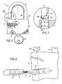
- FIGS. 1 to 5 show an embodiment of a seal according to the invention.
- the seal is made from a padlock 1 which mainly comprises a housing 2 and a fastening element 3 such as a metal bow.
- the housing 2 encloses a lock mechanism for locking at least one end of the fastening element 3.
- the fastening element 3 comprises a free end 33 provided with a notch 31 intended to receive a failure (not shown) of the lock mechanism for locking.
- the other end 34 of the element 3 is held in the housing 2 so as to allow the rotation of the element 3 around this end when the lock is unlocked.
- the end 34 may also include a notch 32 for receiving a lockout failure.
- the locking means of the lock mechanism of the housing 2 are actuated in the direction of unlocking by rotation of a cylinder 7 about its axis by means of a key 8 previously introduced into a slot (71).
- lock cylinder 7 ( figure 5 ). It is also known that this type of lock can be locked without having to use the key, that is to say without rotation of the lock cylinder. Indeed, when no force is applied to the cylinder by the key 8, the padlock is provided with a return mechanism which holds the cylinder 7 in a rest position as illustrated in FIG. figures 1 and 2 .
- the fault or failures intended to engage in the notch or notches of the fastening element 3 are also mounted with return springs which hold them in the locking position of the fastening element as long as the lock cylinder is not actuated in rotation in the unlocking direction S ( figure 5 ).
- the lock cylinder can be operated in either direction for cause unlocking of the fastener. To close the padlock, simply press the element 3 to move it in translation to the housing 2 and thus lower its ends in the housing and this without movement of the cylinder.
- the lock mechanism which consists in blocking or releasing the ends of the fastening element 3 is well known per se and will not be described in more detail.
- the housing 2 is modified to be able to receive an electronic component 6 which can be broken mechanically.
- a bore 21 is machined on the side of the housing 2 to form a housing for the component 6.
- the component 6 is held in the bore 21 by an element 4 which comprises a cavity 41 in which are arranged a spring 5 and a portion of the component 6.
- a recess 22, whose shape corresponds to that of the element 4 is also machined in the housing 2 upstream of the bore 21.
- the element 4 can be fixed in the recess 22 of the housing by means of a simple bonding. Fixing the element 4 in the housing may, however, be reinforced by a pin 9 disposed in a passage 23 pierced in the housing and in a portion of the element 4 which does not include the cavity 41 ( figure 4 ).
- the bore 21 extends both in a portion of the housing 2 and in a portion of the cylinder 7 of the padlock lock.
- the portion of the bore 21 located in the housing and the portion of the bore 21 in the cylinder 7 are aligned only when the latter is in the locking position.
- the bore 21 forms a common housing in the housing and the cylinder for the component 6 only when the cylinder is in the locking position, that is to say its rest position.
- the depth of the bore 21 in the cylinder 7 does not exceed the length of the component 6 to ensure that the latter, once held in abutment at the bottom of the bore 21, will be present at both in the cylinder 7 and in the housing 2 ( figure 5 ).
- the depth of the bore 21 in the cylinder 7 is about 2 mm.
- the component 6 is in opposition to any rotational movement of the cylinder 7 relative to the housing 2 which forms a stator. Because of its mechanical fragility, any attempt to unlock the padlock by actuating the cylinder will cause the breakage of the component. Therefore, the integrity of the seal according to the invention is provided by the mechanical integrity and, therefore, the electronic component.
- An electronic component that can be used in the seal according to the invention is a passive electronic component remotely searchable as a transponder of the type of those injected or implanted in domestic animals for their identification.
- a transponder is a device that transmits the information it has in memory when activated by a transceiver. Possibly, it can store new information.
- such an electronic component comprises an electronic circuit which comprises antenna means, such as a coil wound around a ferrite core, and an electronic part consisting essentially of storage means.
- the antenna means serve not only for the transmission of data but also to receive an activation field for the supply of electrical energy to the electronic circuit.
- An example of a passive transponder that can be used in the present invention is a model (B T-IS 6110 with an industrial and non-animal identification code in accordance with the ISO 11784 standard) of DATAMARS SA.
- This model of transponder comprises a miniature electronic circuit which is wrapped in a glass cylinder of very small dimensions, namely 14 mm in length and 2 mm in diameter.
- the electronic circuit comprises a memory of a capacity of 128 bits which can be programmable or multi-page (transponder type "Full Duplex" (FDX)).
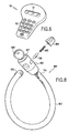
- the reading of the data stored in the transponder can be performed for example with the aid of a portable reader 50 represented in FIG. figure 6 .
- a portable reader 50 represented in FIG. figure 6 .
- Such a reader may include in particular a display screen 51, a keyboard 52 and / or storage means interrogated data.
- the reader activates the radio frequency (RF) transponder, for example at a frequency of 134.2 kHz. This wave charges a capacitance present in the transponder circuit. When the latter discharges, it sends back to the reader a code or information, stored in the transponder memory.
- RF radio frequency
- each interrogated transponder is thus sent to the reader 50 and displayed on its screen 51 and / or stored in its memory, or transferred, via a serial link, to a computer.
- Software may make it possible to correlate the seal identification number (the transponder code) with various data such as, for example, the location, and / or the name of the inspector who installed the seal, and / or the date of sealing.
- the system thus constituted makes it possible to read the data of the seal at a distance of up to about 30 cm, which is sufficient for most uses.
- transponder described above is particularly suitable for the present invention. Indeed, such components have a very small footprint which allows them to be easily housed in small mobile closure devices such as padlocks.
- the protective envelope of the circuit is made of glass, it can be broken easily and thus allow the destruction of the electronic circuit with little resistance, especially vis-à-vis the shear force applied to the component during the rotation of the lock cylinder.
- the integrity of the latter can be controlled very simply and quickly although it is not apparent. Indeed, any attempt to breach the seal by opening the lock is sanctioned by the mechanical destruction of the component. Thus, the integrity of the component, and therefore that of the seal, will be controlled using a reader. If the component does not respond to an interrogation of the reader it means that the electronic circuit of that one has been damaged and that the integrity of the seal is questionable.
- the seal according to the invention meets the same requirements.
- the seal is provided in the configuration shown in figure 1 , ie with the fastening element 3 unlocked to allow the latter to pass for example in studs or closed rings of a bag or other that it is desired to close inviolably.
- the seal according to the invention is in the configuration shown in FIG. figure 2 where the fastening element is locked in the housing 2. This configuration corresponds to the seal affixed and any attempt to open the lock will cause the destruction of the component and therefore that of the seal.
- FIG. 7 An example of such a means is illustrated in figure 7 .
- the free end 33 of the fastening element 3 is covered with a cap 35 whose width L 2 is greater than the width L 1 of the orifice 24 of the housing 2 in which the end 33 is housed to be locked.
- the inadvertent closure of the padlock can be prevented by removable means on the housing 2, such as an adhesive or a cover which obstructs the orifice 24.
- the removable means may also consist of a spacer, removable or breakable, disposed between the housing and the upper part of the attachment element 3 to hold the latter at a determined distance that prevents the free end from entering the housing.
- the figure 8 shows another embodiment of a multi-purpose seal according to the invention.
- a seal is made from a mobile closure apparatus 100 of the antitheft type for a cycle.
- the fastening element 103 is constituted by a steel cable or a chain, possibly covered with a plastic sheath, one end 134 of which is fixed to a housing 102 enclosing a lock mechanism.
- the other end 133 of the fastening element 103 is left free when it is not locked in the housing 102.
- the housing 102 is modified to receive a component 106 of the same type as that previously described, the latter being held between a portion of the housing 102 and the lock cylinder 107 by means of an element 104 and a spring 105. Any rotation of the cylinder 107 with the aid of a key 108 will destroy component 106.
- the seal according to the invention has the following advantages.
- the information such as an identification code
- the transponder is waterproof and resistant to chemical attack. Therefore, the information can be read even under particular storage conditions.
- the data stored in the seal can be read when it is immersed.
- the data stored in the seal can be easily stored, thanks to a simple serial computer link.
- the extracted data can then be processed quickly, which speeds up and lowers the cost of identification.
- Multi-page transponders can be used to store various types of information, such as information about the nature, provenance, routing steps, or location of the material or sealed product, further increasing the possibilities of the seal. . For example, when routing in several steps, the information may be useful in determining the location or date of any possible breach of the seal.
- the transponder circuit comprises programmable or encryptable means, it is possible to encode or encrypt the data stored in the seal, resulting in an increased level of security.
- the seal has a low manufacturing cost (about 10 Euros depending on the quantity produced for a seal made from a padlock).
- Verification of the integrity of the seal is carried out simply and quickly: if the reader can not read the stored information is that the seal has been violated.
- the seal has a high mechanical strength that allows it to be used as a reliable locking device.
- the seal does not require any special precautions to protect its integrity. Indeed, the integrity indicator, namely the component, is protected inside the closure device against any destruction that may occur during handling of the sealed object.
Landscapes
- Lock And Its Accessories (AREA)
- Casings For Electric Apparatus (AREA)
Abstract
Description
La présente invention concerne un dispositif de scellé pour fermer et marquer des objets. Plus particulièrement, l'invention se rapporte aux dispositifs de scellé qui mettent en ouvre des moyens électroniques d'identification.The present invention relates to a sealing device for closing and marking objects. More particularly, the invention relates to sealing devices that implement electronic identification means.
De nombreux types de scellés sont actuellement utilisés pour contrôler le cheminement ou le stockage de produits ou matériels qui présentent des besoins de sécurité ou de contrôle plus ou moins importants, comme, par exemple, des matières nucléaires, certains types de déchets ou bien de l'argent.Many types of seals are currently used to control the routing or storage of products or equipment that have more or less important security or control requirements, such as, for example, nuclear material, certain types of waste, or 'money.
Les technologies employées pour la réalisation des scellés sont très variées et dépendent principalement de l'usage et des degrés de sécurité demandés.The technologies used for the realization of seals are very varied and depend mainly on the use and the degrees of security required.
Ainsi, lorsqu'on désire s'assurer simplement de l'intégrité d'un objet, tel qu'un sac ou un coffre, la fonction du scellé est de garantir que l'objet n'a pas été ouvert sans autorisation. Dans ce cas, des dispositifs peu onéreux, comme de simples colliers de plastique ou de métal apposés sur les organes d'ouverture de l'objet, peuvent être utilisés. Une simple inspection visuelle de l'intégrité de la structure des colliers suffit alors pour constater que le scellé a été violé ou non.Thus, when it is desired to simply ensure the integrity of an object, such as a bag or a chest, the function of the seal is to ensure that the object has not been opened without authorization. In this case, inexpensive devices, such as simple plastic or metal collars affixed to the opening members of the object, can be used. A simple visual inspection of the integrity of the structure of the collars is then sufficient to find that the seal was violated or not.
Le document
D'autre part, il existe de plus en plus de domaines dans lesquels les scellés doivent non seulement remplir leur fonction de base, qui est de pouvoir attester de l'inviolabilité de l'objet, mais aussi pouvoir fournir des informations durant leur utilisation. Ainsi, il existe actuellement des dispositifs qui comprennent des moyens mécaniques de scellement auxquels sont associés des moyens électroniques ou optiques qui permettent de mémoriser et transmettre des informations.On the other hand, there are more and more areas in which the seals must not only fulfill their basic function, which is to be able to attest to the inviolability of the object, but also to be able to provide information during their use. Thus, there are currently devices that include mechanical sealing means which are associated with electronic or optical means that can store and transmit information.
Cependant, les dispositifs de scellé actuels qui comprennent des moyens électroniques sont complexes et coûteux. Ils sont en général conçus pour un usage spécifique et ne peuvent pas être mis en oeuvre avec n'importe quel type d'objet. De plus, ils présentent une structure mécanique fragile qui les rend très sensibles aux manipulations et aux transports ce qui restreint encore leur utilisation.However, current sealing devices that include electronic means are complex and expensive. They are usually designed for a specific purpose and can not be implemented with any type of object. In addition, they have a fragile mechanical structure that makes them very sensitive to handling and transport which further restricts their use.
Le document
La présente invention vise à remédier aux inconvénients précités et à réaliser un dispositif de scellé à usage multiple de faible coût qui est mécaniquement robuste et qui contient des informations consultables de façon simple et rapide. Le dispositif doit aussi permettre un contrôle sûr et aisé de l'intégrité du scellé.The present invention aims at overcoming the aforementioned drawbacks and at achieving a low-cost, low-cost, multi-purpose seal device which is mechanically robust and which contains searchable information of easy and fast way. The device must also allow a safe and easy control of the integrity of the seal.
Ces buts sont atteints grâce à un scellé multi-usage à serrure, comprenant un appareil de fermeture mobile formé d'un boîtier renfermant une serrure et d'un élément d'attache destiné à être verrouillé dans le boîtier, la serrure comprenant un cylindre mobile dans le boîtier entre une position de verrouillage et une position de déverrouillage, caractérisé en ce qu'il comprend en outre un composant électronique interrogeable à distance qui comprend un moyen de mémorisation de données, le composant étant maintenu à l'aide d'un élément de maintien configuré comme pièce de forme dans un logement qui traverse une partie du boîtier et une partie du cylindre de serrure, lorsque ce dernier se trouve dans la position de verrouillage.These goals are achieved through a multi-purpose lock seal, comprising a movable closure apparatus formed of a lock housing and a fastener member for locking in the housing, the lock including a movable cylinder in the housing between a locking position and an unlocking position, characterized in that it further comprises a remotely interrogable electronic component which comprises a data storage means, the component being maintained by means of an element retainer configured as a shaped member in a housing that passes through a portion of the housing and a portion of the lock cylinder when the lock cylinder is in the locking position.
Ainsi, grâce au scellé selon l'invention, le composant électronique qui permet de mémoriser et de transmettre des informations devient également le témoin de l'intégrité du scellé. Le contrôle de l'intégrité du composant s'effectue par interrogation à distance de celui-ci, ce qui ne nécessite aucun démontage du scellé.Thus, thanks to the seal according to the invention, the electronic component that makes it possible to store and transmit information also becomes a witness to the integrity of the seal. The control of the integrity of the component is carried out by remote interrogation of the latter, which does not require any dismantling of the seal.
Selon l'invention, le boîtier comprend un évidement dont la forme correspond à celle de l'élément de maintien et dans lequel est fixé l'élément de maintien pour retenir le composant électronique dans le logement.According to the invention, the housing comprises a recess whose shape corresponds to that of the holding element and in which is fixed the holding element for retaining the electronic component in the housing.
Plus spécifiquement, l'élément de maintien comprend une cavité destinée à recevoir une partie du composant électronique, un ressort étant disposé entre le fond de la cavité et le composant électronique.More specifically, the holding member comprises a cavity for receiving a portion of the electronic component, a spring being disposed between the bottom of the cavity and the electronic component.
Afin de renforcer la fixation de l'élément de maintien dans le boîtier, le scellé peut comprendre en outre une goupille fixe qui bloque l'élément de maintien dans le boîtier.In order to enhance the attachment of the holding member in the housing, the seal may further include a fixed pin which locks the holding member in the housing.
Le moyen de mémorisation de données du composant électronique peut comprendre des moyens de cryptage des données. Il peut aussi être de type programmable ou multipages.The data storage means of the electronic component may comprise data encryption means. It can also be of programmable type or multipage.
Selon une caractéristique de l'invention, le composant électronique est un transpondeur passif du type transpondeur injectable pour animaux.According to one characteristic of the invention, the electronic component is a passive transponder of the injectable transponder type for animals.
Selon une autre caractéristique de l'invention, le scellé comprend un moyen amovible pour empêcher le verrouillage de l'élément d'attache dans le boîtier.According to another characteristic of the invention, the seal comprises a removable means for preventing locking of the fastening element in the housing.
L'appareil de fermeture mobile peut être un cadenas ou un antivol du type antivol pour cycle.The mobile closure device may be a padlock or antitheft type lock for cycle.
La présente invention à également pour objet un procédé de fabrication d'un scellé multi-usage comprenant un appareil de fermeture mobile formé d'un boîtier refermant une serrure et d'un élément d'attache, la serrure comportant un cylindre mobile dans le boîtier entre une position de verrouillage et de déverrouillage de l'élément d'attache, caractérisé en ce qu'il comprend les étapes suivantes:
- a) perçage d'une ouverture qui traverse une partie du boîtier et une partie du cylindre de serrure lorsqu'il est dans la position de verrouillage, et
- b) installation, dans l'ouverture, d'un composant électronique interrogeable à distance comprenant un moyen de mémorisation de données,
- a) drilling an opening which passes through a portion of the housing and a portion of the lock cylinder when in the locking position, and
- b) installing, in the opening, a remotely interrogatable electronic component comprising data storage means,
Selon l'invention, le procédé comprend en outre les étapes suivantes:
- c) usinage d'un évidemment dans le boîtier en amont de l'ouverture, et
- d) fixation d'un élément de maintien dans l'évidement pour retenir le composant électronique dans le logement, l'élément de maintien étant configuré comme pièce de forme et ayant une forme qui correspond à celle de l'évidement.
- c) machining an obviously in the housing upstream of the opening, and
- d) attaching a holding member in the recess to retain the electronic component in the housing, the holding member being configured as a shaped piece and having a shape corresponding to that of the recess.
Plus particulièrement, l'élément de maintien comprend une cavité destinée à recevoir une partie du composant électronique, un ressort étant disposé entre le fond de la cavité et le composant électronique.More particularly, the holding element comprises a cavity intended to receive a part of the electronic component, a spring being disposed between the bottom of the cavity and the electronic component.
Le procédé peut comprendre en outre une étape e) de fixation d'une goupille pour bloquer l'élément de maintien dans le boîtier.The method may further comprise a step e) of fixing a pin to lock the holding member in the housing.
Il peut aussi comprendre une étape supplémentaire f) d'installation d'un moyen amovible pour empêcher le verrouillage de l'élément d'attache dans le boîtier.It may also comprise an additional step f) of installing a removable means to prevent locking of the fastening element in the housing.
Selon une caractéristique de l'invention, le moyen de mémorisation de données du composant électronique comprend des moyens de cryptage des données. Il peut aussi être de type programmable ou multipages.According to a characteristic of the invention, the data storage means of the electronic component comprises means for encrypting the data. It can also be of programmable type or multipage.
Selon un aspect particulier de l'invention, le composant électronique est un transpondeur passif du type transpondeur injectable pour animaux.According to a particular aspect of the invention, the electronic component is a passive transponder of the injectable transponder type for animals.
L'appareil de fermeture mobile peut être un cadenas ou bien un antivol du type antivol pour cycle.The mobile closure device may be a padlock or an antitheft lock type cycle.
D'autres caractéristiques et avantages de l'invention ressortiront de la description suivante de modes particuliers de réalisation de l'invention, donnés à titre d'exemples non limitatifs, en référence aux dessins annexés, sur lesquels :
- la
figure 1 est une vue schématique d'un scellé à serrure en position déverrouillée conformément à un premier mode de réalisation selon l'invention, - la
figure 2 est une vue schématique d'un scellé à serrure en position verrouillée selon un premier mode de réalisation de l'invention, - la
figure 3 est une vue en perspective éclatée d'une partie du scellé selon un premier mode de réalisation, - la
figure 4 est une vue schématique de côté du scellé selon un premier mode de réalisation, - la
figure 5 est une vue schématique en coupe selon le plan V de lafigure 2 selon un premier mode de réalisation de l'invention, - la
figure 6 est une vue en perspective d'un exemple de lecteur portable, - la
figure 7 est une vue de détail agrandie d'une partie VII de lafigure 1 , et - la
figure 8 est une vue en perspective d'un scellé selon un deuxième mode de réalisation de l'invention.
- the
figure 1 is a schematic view of a lock seal in unlocked position according to a first embodiment according to the invention, - the
figure 2 is a schematic view of a lock seal in the locked position according to a first embodiment of the invention, - the
figure 3 is an exploded perspective view of a portion of the seal according to a first embodiment, - the
figure 4 is a schematic side view of the seal according to a first embodiment, - the
figure 5 is a schematic sectional view along the plane V of thefigure 2 according to a first embodiment of the invention, - the
figure 6 is a perspective view of an example of a portable player, - the
figure 7 is an enlarged detail view of a part VII of thefigure 1 , and - the
figure 8 is a perspective view of a seal according to a second embodiment of the invention.
Afin de ne pas compliquer inutilement la description, la présente invention sera essentiellement décrite en relation avec un appareil de fermeture mobile du type cadenas. Cependant, il apparaîtra clairement que la présente invention s'applique à tout type d'appareil de fermeture mobile qui comprend un boîtier renfermant un mécanisme de serrure actionnable par rotation d'un cylindre à l'aide d'une clé ou similaire.In order not to unnecessarily complicate the description, the present invention will be essentially described in connection with a mobile locking device of the padlock type. However, it will be apparent that the present invention applies to any type of closure apparatus mobile which comprises a housing enclosing a lock mechanism operable by rotation of a cylinder with a key or the like.
Les
Dans ce premier exemple de réalisation, le scellé est fabriqué à partir d'un cadenas 1 qui comprend principalement un boîtier 2 et un élément d'attache 3 tel qu'un arceau métallique. Le boîtier 2 renferme un mécanisme de serrure destiné à verrouiller au moins une des extrémités de l'élément d'attache 3. Tel que représenté en
Conformément à l'invention, le boîtier 2 est modifié pour pouvoir recevoir un composant électronique 6 qui peut être brisé mécaniquement. A cet effet, comme représenté en
Comme illustré en
Ce qui est important, c'est que la profondeur de l'alésage 21 dans le cylindre 7 ne dépasse pas la longueur du composant 6 pour garantir que ce dernier, une fois maintenu en butée au fond de l'alésage 21, sera présent à la fois dans le cylindre 7 et dans le boîtier 2 (
Un composant électronique qui peut être utilisé dans le scellé selon l'invention est un composant électronique passif interrogeable à distance comme un transpondeur du type de ceux injectés ou implantés dans les animaux domestiques pour leur identification. Un transpondeur est un dispositif qui transmet l'information qu'il a en mémoire lorsqu'il est activé par un émetteur-récepteur. Eventuellement, il peut stocker de nouvelles informations.An electronic component that can be used in the seal according to the invention is a passive electronic component remotely searchable as a transponder of the type of those injected or implanted in domestic animals for their identification. A transponder is a device that transmits the information it has in memory when activated by a transceiver. Possibly, it can store new information.
Plus précisément, un tel composant électronique comporte un circuit électronique qui comprend des moyens formant antenne, comme une bobine enroulée autour d'un noyau de ferrite, et une partie électronique essentiellement composée de moyens de mémorisation. Les moyens formant antenne servent non seulement à la transmission des données mais aussi à recevoir un champ d'activation pour l'alimentation en énergie électrique du circuit électronique.More specifically, such an electronic component comprises an electronic circuit which comprises antenna means, such as a coil wound around a ferrite core, and an electronic part consisting essentially of storage means. The antenna means serve not only for the transmission of data but also to receive an activation field for the supply of electrical energy to the electronic circuit.
Un exemple de transpondeur passif pouvant être utilisé dans la présente invention est un modèle (B T-IS 6110 avec un code d'identification industriel et non animal en accord avec la norme ISO 11784) de la société DATAMARS SA. Ce modèle de transpondeur comprend un circuit électronique miniature qui est enveloppé dans un cylindre de verre de très petites dimensions, à savoir 14 mm de longueur pour 2 mm de diamètre. Le circuit électronique comporte une mémoire d'une capacité de 128 bits qui peut être programmable ou multipages (transpondeur de type "Full Duplex" (FDX)).An example of a passive transponder that can be used in the present invention is a model (B T-IS 6110 with an industrial and non-animal identification code in accordance with the ISO 11784 standard) of DATAMARS SA. This model of transponder comprises a miniature electronic circuit which is wrapped in a glass cylinder of very small dimensions, namely 14 mm in length and 2 mm in diameter. The electronic circuit comprises a memory of a capacity of 128 bits which can be programmable or multi-page (transponder type "Full Duplex" (FDX)).
La lecture des données mémorisées dans le transpondeur, telles que l'identité du scellé ou des informations sur le contenu scellé, peut être effectuée par exemple à l'aide d'un lecteur portable 50 représenté en
Le code et/ou les informations de chaque transpondeur interrogé sont ainsi envoyés vers le lecteur 50 et affichés sur son écran 51 et/ou stockés dans sa mémoire, ou transférés, via une liaison série, vers un ordinateur. Un logiciel peut permettre d'établir la corrélation entre le numéro d'identification du scellé (le code du transpondeur) et des données diverses telles que par exemple le lieu, et/ou le nom de l'inspecteur ayant installé le scellé, et/ou la date de pose du scellé. Le système ainsi constitué permet la lecture des données du scellé à une distance pouvant aller jusqu'à 30 cm environ, ce qui est suffisant pour la plupart des utilisations.The code and / or information of each interrogated transponder are thus sent to the
Le type de transpondeur décrit ci-dessus est particulièrement adapté pour la présente invention. En effet, de tels composants présentent un encombrement très réduit ce qui permet de les loger facilement dans de petits appareils de fermeture mobiles tels que des cadenas. De plus, l'enveloppe de protection du circuit étant en verre, elle peut être brisée facilement et permettre ainsi la destruction du circuit électronique avec peu de résistance, en particulier vis-à-vis de l'effort de cisaillement appliqué au composant lors de la rotation du cylindre de serrure.The type of transponder described above is particularly suitable for the present invention. Indeed, such components have a very small footprint which allows them to be easily housed in small mobile closure devices such as padlocks. In addition, since the protective envelope of the circuit is made of glass, it can be broken easily and thus allow the destruction of the electronic circuit with little resistance, especially vis-à-vis the shear force applied to the component during the rotation of the lock cylinder.
Ainsi, grâce à cette conception de scellé propre à l'invention, l'intégrité de ce dernier peut être contrôlée de manière très simple et rapide bien qu'elle ne soit pas apparente. En effet, toute tentative de violation du scellé par ouverture du cadenas est sanctionnée par la destruction mécanique du composant. Ainsi, l'intégrité du composant, et par conséquent celle du scellé, sera contrôlée à l'aide d'un lecteur. Si le composant ne répond pas à une interrogation du lecteur cela signifie que le circuit électronique de celui-là a subi des dommages et que l'intégrité du scellé est contestable.Thus, thanks to this seal design of the invention, the integrity of the latter can be controlled very simply and quickly although it is not apparent. Indeed, any attempt to breach the seal by opening the lock is sanctioned by the mechanical destruction of the component. Thus, the integrity of the component, and therefore that of the seal, will be controlled using a reader. If the component does not respond to an interrogation of the reader it means that the electronic circuit of that one has been damaged and that the integrity of the seal is questionable.
Selon le principe du scellé, celui-ci ne peut être apposé qu'une fois sans atteinte à son intégrité. Le scellé selon l'invention répond aux mêmes exigences. Le scellé est fourni dans la configuration représentée en
Afin d'empêcher toute fermeture intempestive du cadenas et donc la perte du scellé lors de son transport ou de sa manipulation avant son utilisation, il peut être prévu des moyens amovibles sur l'élément d'attache, le boîtier ou les deux. Un exemple d'un tel moyen est illustré en
La
Le mode de réalisation présenté en
Le scellé selon l'invention présente les avantages suivants.The seal according to the invention has the following advantages.
Les informations, telles qu'un code d'identification, peuvent être lues sans démontage ou altération du scellé lorsque celui-ci est apposé. Grâce à l'enveloppe de verre qui protège le circuit électronique, le transpondeur est étanche et résistant aux attaques chimiques. Par conséquent, les informations peuvent être lues même dans des conditions de stockage particulières. Ainsi, par exemple, les données mémorisées dans le scellé peuvent être lues lorsque celui-ci est immergé.The information, such as an identification code, can be read without dismantling or tampering with the seal when it is affixed. Thanks to the glass envelope that protects the electronic circuit, the transponder is waterproof and resistant to chemical attack. Therefore, the information can be read even under particular storage conditions. Thus, for example, the data stored in the seal can be read when it is immersed.
L'utilisation d'un lecteur pour l'identification et l'interrogation du scellé facilite le travail de contrôle. Il suffit de transporter le lecteur sur chacun des sites à contrôler. Il n'est pas nécessaire d'emmener chacun des scellés vers un laboratoire ou un centre d'analyse pour disposer de moyens d'ouverture et de lecture particuliers.The use of a reader for identification and interrogation of the seal facilitates the control work. Just carry the reader on each site to control. It is not necessary to take each seal to a laboratory or an analysis center to have special means of opening and reading.
Les données mémorisées dans le scellé peuvent être facilement stockées, grâce à une simple liaison informatique série. On peut alors traiter rapidement les données extraites, ce qui accélère et abaisse le coût de l'identification.The data stored in the seal can be easily stored, thanks to a simple serial computer link. The extracted data can then be processed quickly, which speeds up and lowers the cost of identification.
Il est possible d'utiliser des transpondeurs multipages afin de stocker des informations diverses, comme des informations sur la nature, la provenance, les étapes de cheminement ou bien le lieu de départ du matériel ou produit scellé, ce qui augmente encore les possibilités du scellé. Lors d'un acheminement en plusieurs étapes par exemple, les informations pourront être utiles pour déterminer le lieu ou la date d'un éventuel viol du scellé.Multi-page transponders can be used to store various types of information, such as information about the nature, provenance, routing steps, or location of the material or sealed product, further increasing the possibilities of the seal. . For example, when routing in several steps, the information may be useful in determining the location or date of any possible breach of the seal.
Lorsque le circuit du transpondeur comprend des moyens programmables ou encryptables, il est possible de coder ou crypter les données mémorisées dans le scellé, d'où un niveau de sécurité accru.When the transponder circuit comprises programmable or encryptable means, it is possible to encode or encrypt the data stored in the seal, resulting in an increased level of security.
Le scellé présente un faible coût de fabrication (environ 10 Euros suivant la quantité produit pour un scellé fabriqué à partir d'un cadenas).The seal has a low manufacturing cost (about 10 Euros depending on the quantity produced for a seal made from a padlock).
La vérification de l'intégrité du scellé est réalisée de façon simple et rapide: si le lecteur ne peut lire les informations mémorisées c'est que le scellé à été violé.Verification of the integrity of the seal is carried out simply and quickly: if the reader can not read the stored information is that the seal has been violated.
Le scellé présente une robustesse mécanique importante qui permet de l'utiliser comme appareil de fermeture fiable. De plus, une fois posé, le scellé ne nécessite aucune précaution particulière pour protéger son intégrité. En effet, le témoin d'intégrité, à savoir le composant, est protégé à l'intérieur de l'appareil de fermeture contre toute destruction qui pourrait intervenir lors de la manipulation de l'objet scellé.The seal has a high mechanical strength that allows it to be used as a reliable locking device. In addition, once installed, the seal does not require any special precautions to protect its integrity. Indeed, the integrity indicator, namely the component, is protected inside the closure device against any destruction that may occur during handling of the sealed object.
Il est également possible d'avoir une clé unique pour une pluralité d'appareils de fermeture utilisés comme scellés selon l'invention. Ce qui simplifie encore leur utilisation.It is also possible to have a single key for a plurality of closures used as seals according to the invention. Which further simplifies their use.
Claims (18)
- A multi-purpose seal with lock comprising a mobile closure apparatus (1) formed of a housing (2) containing a lock and an attachment element (3) intended to be locked in the housing, said lock comprising a cylinder (7) movable in the housing between a locked position and an unlocked position, characterised in that it further comprises a remotely interrogatable electronic component (6) which comprises a data storage means, said component being held in a receptacle (21) which passes through part of the housing (2) and part of the lock cylinder (7), when the latter is in the locked position, with the assistance of a holding element (4) configured as a shaped part, said housing (2) comprising a recess (22), the shape of which corresponds to that of the holding element (4) and in which is fixed the holding element (4) to retain the electronic component (6) in the receptacle (21)
- A seal according to claim 1, characterised in that the holding element (4) comprises a cavity (41) intended to receive part of the electronic component (6), a spring (5) being arranged between the bottom of the cavity and the electronic component (6).
- A seal according to claim 1 or claim 2, characterised in that it further comprises a fixed pin (9) to immobilise the holding element (4) in the housing (2).
- A seal according to any one of claims 1 to 3, characterised in that the data storage means of the electronic component (6) comprises data encryption means
- A seal according to any one of claims 1 to 4, characterised in that the data storage means of the electronic component (6) is of the programmable or multipage type
- A seal according to any one of claims 1 to 5, characterised in that the electronic component (6) is a passive transponder of the injectable animal transponder type
- A seal according to any one of claims 1 to 6, characterised in that it comprises removable means (35) for preventing the attachment element from being locked in the housing
- A seal according to any one of claims 1 to 7, characterised in that the mobile closure apparatus (1) is a padlock
- A seal according to any one of claims 1 to 7, characterised in that the mobile closure apparatus (100) is an antitheft device of the bicycle antitheft device type
- A method for manufacturing a multi-purpose seal comprising a mobile closure apparatus (1) formed of a housing (2) containing a lock and an attachment element (3), said lock comprising a cylinder (7) movable in the housing between a locked position and an unlocked position of the attachment element, characterised in that it comprises the following steps:a) drilling an opening (21), said opening passing through part of the housing and part of the lock cylinder when it is in the locked position,b) fitting in said opening a remotely interrogatable electronic component (6) comprising a data storage means,c) machining a recess (22) in the housing (2) upstream of the opening (21), andd) fixing a holding element (4), which is configured as a shaped part and the shape of which corresponds to that of the recess (22), in said recess for retaining said electronic component
- A method according to claim 10, characterised in that the holding element (4) comprises a cavity (41) intended to receive part of the electronic component (6), a spring (5) being arranged between the bottom of the cavity and the electronic component (6)
- A method according to claim 10 or claim 11, characterised in that it further comprises a step e) of fixing a pin (9) to immobilise the holding element (4) in the housing (2)
- A method according to any one of claims 10 to 12, characterised in that it further comprises a step f) of fitting removable means (35) for preventing the attachment element from being locked in the housing
- A method according to any one of claims 10 to 13, characterised in that the data storage means of the electronic component (6) comprises data encryption means
- A method according to any one of claims 10 to 14, characterised in that the data storage means of the electronic component (6) is of the programmable or multipage type
- A method according to any one of claims 10 to 15, characterised in that the electronic component (6) is a passive transponder of the injectable animal transponder type
- A method according to any one of claims 10 to 16, characterised in that the mobile closure apparatus (1) is a padlock
- A method according to any one of claims 10 to 16, characterised in that the mobile closure apparatus (100) is an antitheft device of the bicycle antitheft device type
Priority Applications (1)
| Application Number | Priority Date | Filing Date | Title |
|---|---|---|---|
| EP20030730200 EP1511909B9 (en) | 2002-05-13 | 2003-05-07 | Multipurpose seal with lock and method of manufacturing a multipurpose seal |
Applications Claiming Priority (4)
| Application Number | Priority Date | Filing Date | Title |
|---|---|---|---|
| EP02291188 | 2002-05-13 | ||
| EP20020291188 EP1371797A1 (en) | 2002-05-13 | 2002-05-13 | Multi-purpose seal with a lock |
| EP20030730200 EP1511909B9 (en) | 2002-05-13 | 2003-05-07 | Multipurpose seal with lock and method of manufacturing a multipurpose seal |
| PCT/EP2003/050150 WO2003095773A1 (en) | 2002-05-13 | 2003-05-07 | Multipurpose seal with lock |
Publications (3)
| Publication Number | Publication Date |
|---|---|
| EP1511909A1 EP1511909A1 (en) | 2005-03-09 |
| EP1511909B1 EP1511909B1 (en) | 2011-01-19 |
| EP1511909B9 true EP1511909B9 (en) | 2011-03-09 |
Family
ID=29414823
Family Applications (2)
| Application Number | Title | Priority Date | Filing Date |
|---|---|---|---|
| EP20020291188 Withdrawn EP1371797A1 (en) | 2002-05-13 | 2002-05-13 | Multi-purpose seal with a lock |
| EP20030730200 Expired - Lifetime EP1511909B9 (en) | 2002-05-13 | 2003-05-07 | Multipurpose seal with lock and method of manufacturing a multipurpose seal |
Family Applications Before (1)
| Application Number | Title | Priority Date | Filing Date |
|---|---|---|---|
| EP20020291188 Withdrawn EP1371797A1 (en) | 2002-05-13 | 2002-05-13 | Multi-purpose seal with a lock |
Country Status (13)
| Country | Link |
|---|---|
| US (1) | US7178369B2 (en) |
| EP (2) | EP1371797A1 (en) |
| JP (1) | JP4435678B2 (en) |
| AR (1) | AR039998A1 (en) |
| AT (1) | ATE496188T1 (en) |
| AU (1) | AU2003240836A1 (en) |
| BR (1) | BR0309931A (en) |
| DE (1) | DE60335799D1 (en) |
| DK (1) | DK1511909T3 (en) |
| ES (1) | ES2358503T3 (en) |
| NO (1) | NO20045395L (en) |
| PT (1) | PT1511909E (en) |
| WO (1) | WO2003095773A1 (en) |
Families Citing this family (23)
| Publication number | Priority date | Publication date | Assignee | Title |
|---|---|---|---|---|
| US7171830B2 (en) * | 2002-04-23 | 2007-02-06 | Petrus Arnoldus Taljaard | Monitoring of operation of a padlock |
| TW590146U (en) | 2003-05-14 | 2004-06-01 | Sinox Co Ltd | Padlock structure with hook locking and opening |
| US7007796B2 (en) * | 2004-05-04 | 2006-03-07 | Mei-Shual Cosmetics Co., Ltd. | Opening device for cosmetic compacts |
| US8353184B2 (en) | 2005-01-21 | 2013-01-15 | Sinox Company Ltd. | Tamper indicating padlock |
| US7828342B2 (en) * | 2005-07-29 | 2010-11-09 | Terahop Networks, Inc. | Reusable locking body, of bolt-type seal lock, having open-ended passageway and U-shaped bolt |
| US7438334B2 (en) * | 2005-07-29 | 2008-10-21 | Terry Daniel J | Bolt-type seal lock |
| TWI292006B (en) | 2006-01-05 | 2008-01-01 | Sinox Co Ltd | Lock box |
| US20070262594A1 (en) * | 2006-05-05 | 2007-11-15 | Tebco Pty Limited | Padlock with security seal |
| ATE506647T1 (en) * | 2006-12-20 | 2011-05-15 | Delaval Holding Ab | IMPROVEMENTS IN DATA ENTRY IN FACILITIES THAT PERFORM ANIMAL-RELATED OPERATIONS |
| AU2008261557A1 (en) * | 2007-06-15 | 2008-12-18 | Matthew Henderson | A transponder bolt seal and a housing for a transponder |
| US8274365B2 (en) * | 2008-04-14 | 2012-09-25 | The Eastern Company | Smart lock system |
| DE102009052419A1 (en) * | 2008-12-02 | 2010-06-10 | Dorma Gmbh + Co. Kg | Hardware for a sliding glass door |
| DE102009052418A1 (en) | 2008-12-02 | 2010-06-10 | Dorma Gmbh + Co. Kg | fitting |
| DE102009052417A1 (en) * | 2008-12-02 | 2010-06-10 | Dorma Gmbh + Co. Kg | Fitting for a glass door |
| FR2951570B1 (en) * | 2009-10-19 | 2012-06-29 | Thoonsen Trading | ANTI-THEFT DEVICE FOR SALES ARTICLES |
| DE102011009011B4 (en) * | 2011-01-20 | 2023-10-05 | ABUS August Bremicker Söhne Kommanditgesellschaft | Padlock for securing and monitoring a switch |
| US20120186308A1 (en) | 2011-01-20 | 2012-07-26 | Abus August Bremicker Soehne Kg | Padlock for securing and monitoring a switch |
| US8640513B2 (en) | 2011-06-22 | 2014-02-04 | The Stanley Works Israel Ltd. | Electronic and manual lock assembly |
| US8640514B2 (en) | 2011-06-22 | 2014-02-04 | The Stanley Works Israel Ltd. | Electronic and manual lock assembly |
| US8806905B2 (en) * | 2012-04-19 | 2014-08-19 | Master Lock Company Llc | Padlock assembly |
| US9607458B1 (en) | 2013-09-13 | 2017-03-28 | The Boeing Company | Systems and methods to manage access to a physical space |
| KR101905022B1 (en) * | 2016-06-30 | 2018-10-05 | 옥타코 주식회사 | locking apparatus using fingerprint scan-module with enhanced security |
| RU2703890C1 (en) * | 2018-09-19 | 2019-10-22 | Общество с ограниченной ответственностью "ВОСХОД-2" | Electronic sealing system |
Family Cites Families (13)
| Publication number | Priority date | Publication date | Assignee | Title |
|---|---|---|---|---|
| US1515302A (en) * | 1922-05-24 | 1924-11-11 | Harry F George | Locking means |
| US2666318A (en) * | 1950-11-03 | 1954-01-19 | American Hardware Corp | Combined lock and seal device |
| US4811578A (en) * | 1983-08-18 | 1989-03-14 | John F. Masoncup | Padlock with tamper-actuated audible and/or inaudible alarm |
| AU575465B2 (en) * | 1985-02-05 | 1988-07-28 | Encrypta Electronics Limited | Apparatus for recording the opening or closing of a closure member |
| ATE137912T1 (en) * | 1991-09-13 | 1996-06-15 | Rodney Arthur Stafford | ELECTRONIC ANIMAL IDENTIFICATION SYSTEM |
| NL9300283A (en) * | 1993-02-12 | 1994-09-01 | Kema Nv | Sealing system for an object, and a seal for that. |
| US5632168A (en) * | 1994-04-07 | 1997-05-27 | Honda Lock Mfg. Co., Ltd. | Key lock device |
| DE19709364C2 (en) * | 1997-03-07 | 1998-12-24 | Diehl Ident Gmbh | Seal for a split housing |
| DE29823528U1 (en) * | 1998-03-20 | 1999-07-22 | Ikon Praezisionstechnik | Device for detecting an unauthorized use of the locking channel of a lock, lock cylinder or padlock |
| US6265973B1 (en) * | 1999-04-16 | 2001-07-24 | Transguard Industries, Inc. | Electronic security seal |
| GB9914711D0 (en) * | 1999-06-23 | 1999-08-25 | Leck Michael J | Electronic seal,methods and security system |
| GB2368174A (en) * | 2000-10-19 | 2002-04-24 | Encrypta Electronics Ltd | Security seal device with detatchable cable display indicating reopening |
| US7239238B2 (en) * | 2004-03-30 | 2007-07-03 | E. J. Brooks Company | Electronic security seal |
-
2002
- 2002-05-13 EP EP20020291188 patent/EP1371797A1/en not_active Withdrawn
-
2003
- 2003-05-07 WO PCT/EP2003/050150 patent/WO2003095773A1/en active Application Filing
- 2003-05-07 US US10/513,325 patent/US7178369B2/en not_active Expired - Fee Related
- 2003-05-07 DE DE60335799T patent/DE60335799D1/en not_active Expired - Lifetime
- 2003-05-07 PT PT03730200T patent/PT1511909E/en unknown
- 2003-05-07 BR BR0309931A patent/BR0309931A/en not_active Application Discontinuation
- 2003-05-07 AT AT03730200T patent/ATE496188T1/en active
- 2003-05-07 AU AU2003240836A patent/AU2003240836A1/en not_active Abandoned
- 2003-05-07 ES ES03730200T patent/ES2358503T3/en not_active Expired - Lifetime
- 2003-05-07 DK DK03730200T patent/DK1511909T3/en active
- 2003-05-07 JP JP2004503750A patent/JP4435678B2/en not_active Expired - Fee Related
- 2003-05-07 EP EP20030730200 patent/EP1511909B9/en not_active Expired - Lifetime
- 2003-05-12 AR ARP030101636 patent/AR039998A1/en active IP Right Grant
-
2004
- 2004-12-10 NO NO20045395A patent/NO20045395L/en not_active Application Discontinuation
Also Published As
| Publication number | Publication date |
|---|---|
| EP1511909A1 (en) | 2005-03-09 |
| EP1511909B1 (en) | 2011-01-19 |
| JP2005533941A (en) | 2005-11-10 |
| NO20045395L (en) | 2005-01-25 |
| DE60335799D1 (en) | 2011-03-03 |
| EP1371797A1 (en) | 2003-12-17 |
| ATE496188T1 (en) | 2011-02-15 |
| AU2003240836A1 (en) | 2003-11-11 |
| BR0309931A (en) | 2005-02-09 |
| WO2003095773A1 (en) | 2003-11-20 |
| JP4435678B2 (en) | 2010-03-24 |
| US20050210932A1 (en) | 2005-09-29 |
| US7178369B2 (en) | 2007-02-20 |
| AR039998A1 (en) | 2005-03-09 |
| PT1511909E (en) | 2011-03-18 |
| DK1511909T3 (en) | 2011-03-14 |
| ES2358503T3 (en) | 2011-05-11 |
Similar Documents
| Publication | Publication Date | Title |
|---|---|---|
| EP1511909B9 (en) | Multipurpose seal with lock and method of manufacturing a multipurpose seal | |
| EP1556622B1 (en) | Fixing member comprising an integrity control system | |
| EP1766587B1 (en) | Method for securely transporting value documents and objects and a box for carrying out said method | |
| EP1087334B1 (en) | Multi-use electronic seal with passive transponder | |
| WO2013092882A1 (en) | Installation comprising a glove box and a glove change device incorporating monitoring of the glove change | |
| GB2368174A (en) | Security seal device with detatchable cable display indicating reopening | |
| EP0133685B1 (en) | Security system for transporting money or bank valuables | |
| EP1599832B1 (en) | Multiple transponder seal device | |
| EP1092615A1 (en) | Device for monitoring parked objects, with antitheft means | |
| FR2925926A1 (en) | SECURE LATCHING AND UNLOCKING DEVICE USING A KEY OF A BUFFER ON A FRAME | |
| EP0417022A1 (en) | Unfalsifiable seal particularly for containers of any kind | |
| FR2821463A1 (en) | DEVICE FOR AUTHENTICATING MINERALOGIC PLATES | |
| FR2892214A1 (en) | DEVICE FOR IDENTIFYING AND PROTECTING AN ELEMENT WHERE WE WISH TO KNOW THE INTEGRITY | |
| EP4147992B1 (en) | Integrity protection system for sensitive assets | |
| EP0259534B1 (en) | Security pocket case | |
| FR2713379A1 (en) | Sealing tie e.g. for container or suitcase | |
| FR2713809A1 (en) | Marking device | |
| FR3028847A1 (en) | DEVICE FOR PROTECTING THE CONTENT OF A CONTAINER AND METHOD FOR THE USE OF SUCH A SEAL | |
| FR2821881A1 (en) | Cash transport security system distributes routing cards compares with radio zones will mark cash | |
| WO1996038824A1 (en) | Device for storing small objects and for managing and monitoring entry and removal of such objects | |
| FR2717154A1 (en) | Fastener for transport container | |
| FR2821880A1 (en) | Security device for transport of bank notes comprises neutralization device of notes fixed against face of bank note packet which is triggered by micro-programmed control circuit |
Legal Events
| Date | Code | Title | Description |
|---|---|---|---|
| PUAI | Public reference made under article 153(3) epc to a published international application that has entered the european phase |
Free format text: ORIGINAL CODE: 0009012 |
|
| 17P | Request for examination filed |
Effective date: 20041210 |
|
| AK | Designated contracting states |
Kind code of ref document: A1 Designated state(s): AT BE BG CH CY CZ DE DK EE ES FI FR GB GR HU IE IT LI LU MC NL PT RO SE SI SK TR |
|
| AX | Request for extension of the european patent |
Extension state: AL LT LV MK |
|
| DAX | Request for extension of the european patent (deleted) | ||
| 17Q | First examination report despatched |
Effective date: 20070329 |
|
| GRAP | Despatch of communication of intention to grant a patent |
Free format text: ORIGINAL CODE: EPIDOSNIGR1 |
|
| RTI1 | Title (correction) |
Free format text: MULTIPURPOSE SEAL WITH LOCK AND METHOD |
|
| RTI1 | Title (correction) |
Free format text: MULTIPURPOSE SEAL WITH LOCK AND METHOD OF MANUFACTURING A MULTIPURPOSE SEAL |
|
| RAP1 | Party data changed (applicant data changed or rights of an application transferred) |
Owner name: EUROPEAN UNION |
|
| RAP1 | Party data changed (applicant data changed or rights of an application transferred) |
Owner name: THE EUROPEAN UNION, REPRESENTED BY THE EUROPEAN CO |
|
| GRAS | Grant fee paid |
Free format text: ORIGINAL CODE: EPIDOSNIGR3 |
|
| GRAA | (expected) grant |
Free format text: ORIGINAL CODE: 0009210 |
|
| AK | Designated contracting states |
Kind code of ref document: B1 Designated state(s): AT BE BG CH CY CZ DE DK EE ES FI FR GB GR HU IE IT LI LU MC NL PT RO SE SI SK TR |
|
| REG | Reference to a national code |
Ref country code: GB Ref legal event code: FG4D Free format text: NOT ENGLISH |
|
| REG | Reference to a national code |
Ref country code: CH Ref legal event code: EP |
|
| REG | Reference to a national code |
Ref country code: IE Ref legal event code: FG4D Free format text: LANGUAGE OF EP DOCUMENT: FRENCH |
|
| REF | Corresponds to: |
Ref document number: 60335799 Country of ref document: DE Date of ref document: 20110303 Kind code of ref document: P |
|
| REG | Reference to a national code |
Ref country code: DE Ref legal event code: R096 Ref document number: 60335799 Country of ref document: DE Effective date: 20110303 |
|
| REG | Reference to a national code |
Ref country code: DK Ref legal event code: T3 |
|
| REG | Reference to a national code |
Ref country code: PT Ref legal event code: SC4A Free format text: AVAILABILITY OF NATIONAL TRANSLATION Effective date: 20110311 |
|
| REG | Reference to a national code |
Ref country code: NL Ref legal event code: T3 |
|
| REG | Reference to a national code |
Ref country code: SE Ref legal event code: TRGR |
|
| REG | Reference to a national code |
Ref country code: ES Ref legal event code: FG2A Ref document number: 2358503 Country of ref document: ES Kind code of ref document: T3 Effective date: 20110428 |
|
| REG | Reference to a national code |
Ref country code: GR Ref legal event code: EP Ref document number: 20110400929 Country of ref document: GR Effective date: 20110513 |
|
| PG25 | Lapsed in a contracting state [announced via postgrant information from national office to epo] |
Ref country code: CY Free format text: LAPSE BECAUSE OF FAILURE TO SUBMIT A TRANSLATION OF THE DESCRIPTION OR TO PAY THE FEE WITHIN THE PRESCRIBED TIME-LIMIT Effective date: 20110119 Ref country code: BG Free format text: LAPSE BECAUSE OF FAILURE TO SUBMIT A TRANSLATION OF THE DESCRIPTION OR TO PAY THE FEE WITHIN THE PRESCRIBED TIME-LIMIT Effective date: 20110419 Ref country code: SI Free format text: LAPSE BECAUSE OF FAILURE TO SUBMIT A TRANSLATION OF THE DESCRIPTION OR TO PAY THE FEE WITHIN THE PRESCRIBED TIME-LIMIT Effective date: 20110119 |
|
| PG25 | Lapsed in a contracting state [announced via postgrant information from national office to epo] |
Ref country code: EE Free format text: LAPSE BECAUSE OF FAILURE TO SUBMIT A TRANSLATION OF THE DESCRIPTION OR TO PAY THE FEE WITHIN THE PRESCRIBED TIME-LIMIT Effective date: 20110119 |
|
| PLBE | No opposition filed within time limit |
Free format text: ORIGINAL CODE: 0009261 |
|
| STAA | Information on the status of an ep patent application or granted ep patent |
Free format text: STATUS: NO OPPOSITION FILED WITHIN TIME LIMIT |
|
| PG25 | Lapsed in a contracting state [announced via postgrant information from national office to epo] |
Ref country code: RO Free format text: LAPSE BECAUSE OF FAILURE TO SUBMIT A TRANSLATION OF THE DESCRIPTION OR TO PAY THE FEE WITHIN THE PRESCRIBED TIME-LIMIT Effective date: 20110119 Ref country code: CZ Free format text: LAPSE BECAUSE OF FAILURE TO SUBMIT A TRANSLATION OF THE DESCRIPTION OR TO PAY THE FEE WITHIN THE PRESCRIBED TIME-LIMIT Effective date: 20110119 Ref country code: SK Free format text: LAPSE BECAUSE OF FAILURE TO SUBMIT A TRANSLATION OF THE DESCRIPTION OR TO PAY THE FEE WITHIN THE PRESCRIBED TIME-LIMIT Effective date: 20110119 |
|
| 26N | No opposition filed |
Effective date: 20111020 |
|
| PG25 | Lapsed in a contracting state [announced via postgrant information from national office to epo] |
Ref country code: MC Free format text: LAPSE BECAUSE OF NON-PAYMENT OF DUE FEES Effective date: 20110531 |
|
| REG | Reference to a national code |
Ref country code: CH Ref legal event code: PL |
|
| PG25 | Lapsed in a contracting state [announced via postgrant information from national office to epo] |
Ref country code: CH Free format text: LAPSE BECAUSE OF NON-PAYMENT OF DUE FEES Effective date: 20110531 Ref country code: LI Free format text: LAPSE BECAUSE OF NON-PAYMENT OF DUE FEES Effective date: 20110531 |
|
| REG | Reference to a national code |
Ref country code: DE Ref legal event code: R097 Ref document number: 60335799 Country of ref document: DE Effective date: 20111020 |
|
| PGFP | Annual fee paid to national office [announced via postgrant information from national office to epo] |
Ref country code: ES Payment date: 20120509 Year of fee payment: 10 |
|
| PGFP | Annual fee paid to national office [announced via postgrant information from national office to epo] |
Ref country code: AT Payment date: 20120425 Year of fee payment: 10 |
|
| PGFP | Annual fee paid to national office [announced via postgrant information from national office to epo] |
Ref country code: LU Payment date: 20130424 Year of fee payment: 11 |
|
| PGFP | Annual fee paid to national office [announced via postgrant information from national office to epo] |
Ref country code: SE Payment date: 20130425 Year of fee payment: 11 Ref country code: BE Payment date: 20130424 Year of fee payment: 11 Ref country code: IE Payment date: 20130501 Year of fee payment: 11 Ref country code: DK Payment date: 20130424 Year of fee payment: 11 Ref country code: DE Payment date: 20130423 Year of fee payment: 11 Ref country code: GB Payment date: 20130424 Year of fee payment: 11 |
|
| PGFP | Annual fee paid to national office [announced via postgrant information from national office to epo] |
Ref country code: FR Payment date: 20130626 Year of fee payment: 11 Ref country code: FI Payment date: 20130423 Year of fee payment: 11 Ref country code: NL Payment date: 20130424 Year of fee payment: 11 Ref country code: PT Payment date: 20130502 Year of fee payment: 11 Ref country code: GR Payment date: 20130424 Year of fee payment: 11 Ref country code: IT Payment date: 20130424 Year of fee payment: 11 |
|
| PG25 | Lapsed in a contracting state [announced via postgrant information from national office to epo] |
Ref country code: TR Free format text: LAPSE BECAUSE OF FAILURE TO SUBMIT A TRANSLATION OF THE DESCRIPTION OR TO PAY THE FEE WITHIN THE PRESCRIBED TIME-LIMIT Effective date: 20110119 |
|
| PG25 | Lapsed in a contracting state [announced via postgrant information from national office to epo] |
Ref country code: HU Free format text: LAPSE BECAUSE OF FAILURE TO SUBMIT A TRANSLATION OF THE DESCRIPTION OR TO PAY THE FEE WITHIN THE PRESCRIBED TIME-LIMIT Effective date: 20110119 |
|
| REG | Reference to a national code |
Ref country code: PT Ref legal event code: MM4A Free format text: LAPSE DUE TO NON-PAYMENT OF FEES Effective date: 20141107 |
|
| REG | Reference to a national code |
Ref country code: DE Ref legal event code: R119 Ref document number: 60335799 Country of ref document: DE |
|
| REG | Reference to a national code |
Ref country code: NL Ref legal event code: V1 Effective date: 20141201 |
|
| PG25 | Lapsed in a contracting state [announced via postgrant information from national office to epo] |
Ref country code: LU Free format text: LAPSE BECAUSE OF NON-PAYMENT OF DUE FEES Effective date: 20140507 |
|
| REG | Reference to a national code |
Ref country code: DK Ref legal event code: EBP Effective date: 20140531 |
|
| REG | Reference to a national code |
Ref country code: AT Ref legal event code: MM01 Ref document number: 496188 Country of ref document: AT Kind code of ref document: T Effective date: 20140507 |
|
| GBPC | Gb: european patent ceased through non-payment of renewal fee |
Effective date: 20140507 |
|
| PG25 | Lapsed in a contracting state [announced via postgrant information from national office to epo] |
Ref country code: FI Free format text: LAPSE BECAUSE OF NON-PAYMENT OF DUE FEES Effective date: 20140507 Ref country code: PT Free format text: LAPSE BECAUSE OF NON-PAYMENT OF DUE FEES Effective date: 20141107 Ref country code: GR Free format text: LAPSE BECAUSE OF NON-PAYMENT OF DUE FEES Effective date: 20141203 Ref country code: SE Free format text: LAPSE BECAUSE OF NON-PAYMENT OF DUE FEES Effective date: 20140508 |
|
| REG | Reference to a national code |
Ref country code: GR Ref legal event code: ML Ref document number: 20110400929 Country of ref document: GR Effective date: 20141203 |
|
| REG | Reference to a national code |
Ref country code: SE Ref legal event code: EUG |
|
| REG | Reference to a national code |
Ref country code: IE Ref legal event code: MM4A |
|
| REG | Reference to a national code |
Ref country code: DE Ref legal event code: R119 Ref document number: 60335799 Country of ref document: DE Effective date: 20141202 |
|
| PG25 | Lapsed in a contracting state [announced via postgrant information from national office to epo] |
Ref country code: NL Free format text: LAPSE BECAUSE OF NON-PAYMENT OF DUE FEES Effective date: 20141201 Ref country code: AT Free format text: LAPSE BECAUSE OF NON-PAYMENT OF DUE FEES Effective date: 20140507 |
|
| REG | Reference to a national code |
Ref country code: FR Ref legal event code: ST Effective date: 20150130 |
|
| PG25 | Lapsed in a contracting state [announced via postgrant information from national office to epo] |
Ref country code: DE Free format text: LAPSE BECAUSE OF NON-PAYMENT OF DUE FEES Effective date: 20141202 Ref country code: IE Free format text: LAPSE BECAUSE OF NON-PAYMENT OF DUE FEES Effective date: 20140507 Ref country code: IT Free format text: LAPSE BECAUSE OF NON-PAYMENT OF DUE FEES Effective date: 20140507 Ref country code: DK Free format text: LAPSE BECAUSE OF NON-PAYMENT OF DUE FEES Effective date: 20140531 |
|
| PG25 | Lapsed in a contracting state [announced via postgrant information from national office to epo] |
Ref country code: GB Free format text: LAPSE BECAUSE OF NON-PAYMENT OF DUE FEES Effective date: 20140507 Ref country code: FR Free format text: LAPSE BECAUSE OF NON-PAYMENT OF DUE FEES Effective date: 20140602 |
|
| REG | Reference to a national code |
Ref country code: ES Ref legal event code: FD2A Effective date: 20150731 |
|
| PG25 | Lapsed in a contracting state [announced via postgrant information from national office to epo] |
Ref country code: ES Free format text: LAPSE BECAUSE OF NON-PAYMENT OF DUE FEES Effective date: 20140508 |
|
| PG25 | Lapsed in a contracting state [announced via postgrant information from national office to epo] |
Ref country code: BE Free format text: LAPSE BECAUSE OF NON-PAYMENT OF DUE FEES Effective date: 20140531 |