EP1511909B9 - Mehrzwecksiegel mit einem schloss und verfahren zur herstellung eines mehrzwecksiegels - Google Patents
Mehrzwecksiegel mit einem schloss und verfahren zur herstellung eines mehrzwecksiegels Download PDFInfo
- Publication number
- EP1511909B9 EP1511909B9 EP20030730200 EP03730200A EP1511909B9 EP 1511909 B9 EP1511909 B9 EP 1511909B9 EP 20030730200 EP20030730200 EP 20030730200 EP 03730200 A EP03730200 A EP 03730200A EP 1511909 B9 EP1511909 B9 EP 1511909B9
- Authority
- EP
- European Patent Office
- Prior art keywords
- housing
- electronic component
- seal
- lock
- cylinder
- Prior art date
- Legal status (The legal status is an assumption and is not a legal conclusion. Google has not performed a legal analysis and makes no representation as to the accuracy of the status listed.)
- Expired - Lifetime
Links
Images

Classifications
-
- E—FIXED CONSTRUCTIONS
- E05—LOCKS; KEYS; WINDOW OR DOOR FITTINGS; SAFES
- E05B—LOCKS; ACCESSORIES THEREFOR; HANDCUFFS
- E05B39/00—Locks giving indication of authorised or unauthorised unlocking
- E05B39/02—Locks giving indication of authorised or unauthorised unlocking with destructible seal closures or paper closures
-
- Y—GENERAL TAGGING OF NEW TECHNOLOGICAL DEVELOPMENTS; GENERAL TAGGING OF CROSS-SECTIONAL TECHNOLOGIES SPANNING OVER SEVERAL SECTIONS OF THE IPC; TECHNICAL SUBJECTS COVERED BY FORMER USPC CROSS-REFERENCE ART COLLECTIONS [XRACs] AND DIGESTS
- Y10—TECHNICAL SUBJECTS COVERED BY FORMER USPC
- Y10T—TECHNICAL SUBJECTS COVERED BY FORMER US CLASSIFICATION
- Y10T70/00—Locks
- Y10T70/40—Portable
- Y10T70/413—Padlocks
- Y10T70/437—Key-controlled
- Y10T70/446—Rigid shackle
- Y10T70/452—Sliding
- Y10T70/459—Both legs engaged
-
- Y—GENERAL TAGGING OF NEW TECHNOLOGICAL DEVELOPMENTS; GENERAL TAGGING OF CROSS-SECTIONAL TECHNOLOGIES SPANNING OVER SEVERAL SECTIONS OF THE IPC; TECHNICAL SUBJECTS COVERED BY FORMER USPC CROSS-REFERENCE ART COLLECTIONS [XRACs] AND DIGESTS
- Y10—TECHNICAL SUBJECTS COVERED BY FORMER USPC
- Y10T—TECHNICAL SUBJECTS COVERED BY FORMER US CLASSIFICATION
- Y10T70/00—Locks
- Y10T70/40—Portable
- Y10T70/413—Padlocks
- Y10T70/437—Key-controlled
- Y10T70/483—Flexible shackle
-
- Y—GENERAL TAGGING OF NEW TECHNOLOGICAL DEVELOPMENTS; GENERAL TAGGING OF CROSS-SECTIONAL TECHNOLOGIES SPANNING OVER SEVERAL SECTIONS OF THE IPC; TECHNICAL SUBJECTS COVERED BY FORMER USPC CROSS-REFERENCE ART COLLECTIONS [XRACs] AND DIGESTS
- Y10—TECHNICAL SUBJECTS COVERED BY FORMER USPC
- Y10T—TECHNICAL SUBJECTS COVERED BY FORMER US CLASSIFICATION
- Y10T70/00—Locks
- Y10T70/40—Portable
- Y10T70/413—Padlocks
- Y10T70/485—With seal
-
- Y—GENERAL TAGGING OF NEW TECHNOLOGICAL DEVELOPMENTS; GENERAL TAGGING OF CROSS-SECTIONAL TECHNOLOGIES SPANNING OVER SEVERAL SECTIONS OF THE IPC; TECHNICAL SUBJECTS COVERED BY FORMER USPC CROSS-REFERENCE ART COLLECTIONS [XRACs] AND DIGESTS
- Y10—TECHNICAL SUBJECTS COVERED BY FORMER USPC
- Y10T—TECHNICAL SUBJECTS COVERED BY FORMER US CLASSIFICATION
- Y10T70/00—Locks
- Y10T70/40—Portable
- Y10T70/413—Padlocks
- Y10T70/487—Parts, accessories, attachments and adjuncts
- Y10T70/491—Shackles
-
- Y—GENERAL TAGGING OF NEW TECHNOLOGICAL DEVELOPMENTS; GENERAL TAGGING OF CROSS-SECTIONAL TECHNOLOGIES SPANNING OVER SEVERAL SECTIONS OF THE IPC; TECHNICAL SUBJECTS COVERED BY FORMER USPC CROSS-REFERENCE ART COLLECTIONS [XRACs] AND DIGESTS
- Y10—TECHNICAL SUBJECTS COVERED BY FORMER USPC
- Y10T—TECHNICAL SUBJECTS COVERED BY FORMER US CLASSIFICATION
- Y10T70/00—Locks
- Y10T70/80—Parts, attachments, accessories and adjuncts
- Y10T70/8027—Condition indicators
- Y10T70/8054—With recorder
- Y10T70/8081—Electric
-
- Y—GENERAL TAGGING OF NEW TECHNOLOGICAL DEVELOPMENTS; GENERAL TAGGING OF CROSS-SECTIONAL TECHNOLOGIES SPANNING OVER SEVERAL SECTIONS OF THE IPC; TECHNICAL SUBJECTS COVERED BY FORMER USPC CROSS-REFERENCE ART COLLECTIONS [XRACs] AND DIGESTS
- Y10—TECHNICAL SUBJECTS COVERED BY FORMER USPC
- Y10T—TECHNICAL SUBJECTS COVERED BY FORMER US CLASSIFICATION
- Y10T70/00—Locks
- Y10T70/80—Parts, attachments, accessories and adjuncts
- Y10T70/8027—Condition indicators
- Y10T70/8054—With recorder
- Y10T70/8108—Padlock
Definitions
- the present invention relates to a sealing device for closing and marking objects. More particularly, the invention relates to sealing devices that implement electronic identification means.
- seals are currently used to control the routing or storage of products or equipment that have more or less important security or control requirements, such as, for example, nuclear material, certain types of waste, or 'money.
- the function of the seal is to ensure that the object has not been opened without authorization.
- inexpensive devices such as simple plastic or metal collars affixed to the opening members of the object, can be used. A simple visual inspection of the integrity of the structure of the collars is then sufficient to find that the seal was violated or not.
- the document US2666318 discloses a seal and a method of manufacturing a seal according to the preambles of claims 1 and 10. It relates to a mobile closure device in the form of a padlock with the possibility of affixing a seal. In order to prevent unauthorized persons from manipulating the lock, the tape-like seal passes through the padlock cylinder so that it is impossible to rotate the cylinder without the seal being damaged.
- the document EP0863489 has an arrangement with a single-use seal that determines whether a housing has been opened.
- the seal includes a remotely searchable electronic component that is secured by an adhesive to pass through two housing portions. The electronic component is destroyed if the two parts are separated.
- the electronic component is located in a bore above a screw connecting two housing parts. The electronic component and the screw head are embedded in an adhesive. Reaching the screw head to unscrew it will therefore damage the electronic component.
- the present invention aims at overcoming the aforementioned drawbacks and at achieving a low-cost, low-cost, multi-purpose seal device which is mechanically robust and which contains searchable information of easy and fast way.
- the device must also allow a safe and easy control of the integrity of the seal.
- a multi-purpose lock seal comprising a movable closure apparatus formed of a lock housing and a fastener member for locking in the housing, the lock including a movable cylinder in the housing between a locking position and an unlocking position, characterized in that it further comprises a remotely interrogable electronic component which comprises a data storage means, the component being maintained by means of an element retainer configured as a shaped member in a housing that passes through a portion of the housing and a portion of the lock cylinder when the lock cylinder is in the locking position.
- the electronic component that makes it possible to store and transmit information also becomes a witness to the integrity of the seal.
- the control of the integrity of the component is carried out by remote interrogation of the latter, which does not require any dismantling of the seal.
- the housing comprises a recess whose shape corresponds to that of the holding element and in which is fixed the holding element for retaining the electronic component in the housing.
- the holding member comprises a cavity for receiving a portion of the electronic component, a spring being disposed between the bottom of the cavity and the electronic component.
- the seal may further include a fixed pin which locks the holding member in the housing.
- the data storage means of the electronic component may comprise data encryption means. It can also be of programmable type or multipage.
- the electronic component is a passive transponder of the injectable transponder type for animals.
- the seal comprises a removable means for preventing locking of the fastening element in the housing.
- the mobile closure device may be a padlock or antitheft type lock for cycle.
- the holding element comprises a cavity intended to receive a part of the electronic component, a spring being disposed between the bottom of the cavity and the electronic component.
- the method may further comprise a step e) of fixing a pin to lock the holding member in the housing.
- the data storage means of the electronic component comprises means for encrypting the data. It can also be of programmable type or multipage.
- the electronic component is a passive transponder of the injectable transponder type for animals.
- the mobile closure device may be a padlock or an antitheft lock type cycle.
- the present invention will be essentially described in connection with a mobile locking device of the padlock type.
- a mobile locking device of the padlock type comprises a housing enclosing a lock mechanism operable by rotation of a cylinder with a key or the like.
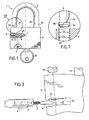
- FIGS. 1 to 5 show an embodiment of a seal according to the invention.
- the seal is made from a padlock 1 which mainly comprises a housing 2 and a fastening element 3 such as a metal bow.
- the housing 2 encloses a lock mechanism for locking at least one end of the fastening element 3.
- the fastening element 3 comprises a free end 33 provided with a notch 31 intended to receive a failure (not shown) of the lock mechanism for locking.
- the other end 34 of the element 3 is held in the housing 2 so as to allow the rotation of the element 3 around this end when the lock is unlocked.
- the end 34 may also include a notch 32 for receiving a lockout failure.
- the locking means of the lock mechanism of the housing 2 are actuated in the direction of unlocking by rotation of a cylinder 7 about its axis by means of a key 8 previously introduced into a slot (71).
- lock cylinder 7 ( figure 5 ). It is also known that this type of lock can be locked without having to use the key, that is to say without rotation of the lock cylinder. Indeed, when no force is applied to the cylinder by the key 8, the padlock is provided with a return mechanism which holds the cylinder 7 in a rest position as illustrated in FIG. figures 1 and 2 .
- the fault or failures intended to engage in the notch or notches of the fastening element 3 are also mounted with return springs which hold them in the locking position of the fastening element as long as the lock cylinder is not actuated in rotation in the unlocking direction S ( figure 5 ).
- the lock cylinder can be operated in either direction for cause unlocking of the fastener. To close the padlock, simply press the element 3 to move it in translation to the housing 2 and thus lower its ends in the housing and this without movement of the cylinder.
- the lock mechanism which consists in blocking or releasing the ends of the fastening element 3 is well known per se and will not be described in more detail.
- the housing 2 is modified to be able to receive an electronic component 6 which can be broken mechanically.
- a bore 21 is machined on the side of the housing 2 to form a housing for the component 6.
- the component 6 is held in the bore 21 by an element 4 which comprises a cavity 41 in which are arranged a spring 5 and a portion of the component 6.
- a recess 22, whose shape corresponds to that of the element 4 is also machined in the housing 2 upstream of the bore 21.
- the element 4 can be fixed in the recess 22 of the housing by means of a simple bonding. Fixing the element 4 in the housing may, however, be reinforced by a pin 9 disposed in a passage 23 pierced in the housing and in a portion of the element 4 which does not include the cavity 41 ( figure 4 ).
- the bore 21 extends both in a portion of the housing 2 and in a portion of the cylinder 7 of the padlock lock.
- the portion of the bore 21 located in the housing and the portion of the bore 21 in the cylinder 7 are aligned only when the latter is in the locking position.
- the bore 21 forms a common housing in the housing and the cylinder for the component 6 only when the cylinder is in the locking position, that is to say its rest position.
- the depth of the bore 21 in the cylinder 7 does not exceed the length of the component 6 to ensure that the latter, once held in abutment at the bottom of the bore 21, will be present at both in the cylinder 7 and in the housing 2 ( figure 5 ).
- the depth of the bore 21 in the cylinder 7 is about 2 mm.
- the component 6 is in opposition to any rotational movement of the cylinder 7 relative to the housing 2 which forms a stator. Because of its mechanical fragility, any attempt to unlock the padlock by actuating the cylinder will cause the breakage of the component. Therefore, the integrity of the seal according to the invention is provided by the mechanical integrity and, therefore, the electronic component.
- An electronic component that can be used in the seal according to the invention is a passive electronic component remotely searchable as a transponder of the type of those injected or implanted in domestic animals for their identification.
- a transponder is a device that transmits the information it has in memory when activated by a transceiver. Possibly, it can store new information.
- such an electronic component comprises an electronic circuit which comprises antenna means, such as a coil wound around a ferrite core, and an electronic part consisting essentially of storage means.
- the antenna means serve not only for the transmission of data but also to receive an activation field for the supply of electrical energy to the electronic circuit.
- An example of a passive transponder that can be used in the present invention is a model (B T-IS 6110 with an industrial and non-animal identification code in accordance with the ISO 11784 standard) of DATAMARS SA.
- This model of transponder comprises a miniature electronic circuit which is wrapped in a glass cylinder of very small dimensions, namely 14 mm in length and 2 mm in diameter.
- the electronic circuit comprises a memory of a capacity of 128 bits which can be programmable or multi-page (transponder type "Full Duplex" (FDX)).
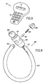
- the reading of the data stored in the transponder can be performed for example with the aid of a portable reader 50 represented in FIG. figure 6 .
- a portable reader 50 represented in FIG. figure 6 .
- Such a reader may include in particular a display screen 51, a keyboard 52 and / or storage means interrogated data.
- the reader activates the radio frequency (RF) transponder, for example at a frequency of 134.2 kHz. This wave charges a capacitance present in the transponder circuit. When the latter discharges, it sends back to the reader a code or information, stored in the transponder memory.
- RF radio frequency
- each interrogated transponder is thus sent to the reader 50 and displayed on its screen 51 and / or stored in its memory, or transferred, via a serial link, to a computer.
- Software may make it possible to correlate the seal identification number (the transponder code) with various data such as, for example, the location, and / or the name of the inspector who installed the seal, and / or the date of sealing.
- the system thus constituted makes it possible to read the data of the seal at a distance of up to about 30 cm, which is sufficient for most uses.
- transponder described above is particularly suitable for the present invention. Indeed, such components have a very small footprint which allows them to be easily housed in small mobile closure devices such as padlocks.
- the protective envelope of the circuit is made of glass, it can be broken easily and thus allow the destruction of the electronic circuit with little resistance, especially vis-à-vis the shear force applied to the component during the rotation of the lock cylinder.
- the integrity of the latter can be controlled very simply and quickly although it is not apparent. Indeed, any attempt to breach the seal by opening the lock is sanctioned by the mechanical destruction of the component. Thus, the integrity of the component, and therefore that of the seal, will be controlled using a reader. If the component does not respond to an interrogation of the reader it means that the electronic circuit of that one has been damaged and that the integrity of the seal is questionable.
- the seal according to the invention meets the same requirements.
- the seal is provided in the configuration shown in figure 1 , ie with the fastening element 3 unlocked to allow the latter to pass for example in studs or closed rings of a bag or other that it is desired to close inviolably.
- the seal according to the invention is in the configuration shown in FIG. figure 2 where the fastening element is locked in the housing 2. This configuration corresponds to the seal affixed and any attempt to open the lock will cause the destruction of the component and therefore that of the seal.
- FIG. 7 An example of such a means is illustrated in figure 7 .
- the free end 33 of the fastening element 3 is covered with a cap 35 whose width L 2 is greater than the width L 1 of the orifice 24 of the housing 2 in which the end 33 is housed to be locked.
- the inadvertent closure of the padlock can be prevented by removable means on the housing 2, such as an adhesive or a cover which obstructs the orifice 24.
- the removable means may also consist of a spacer, removable or breakable, disposed between the housing and the upper part of the attachment element 3 to hold the latter at a determined distance that prevents the free end from entering the housing.
- the figure 8 shows another embodiment of a multi-purpose seal according to the invention.
- a seal is made from a mobile closure apparatus 100 of the antitheft type for a cycle.
- the fastening element 103 is constituted by a steel cable or a chain, possibly covered with a plastic sheath, one end 134 of which is fixed to a housing 102 enclosing a lock mechanism.
- the other end 133 of the fastening element 103 is left free when it is not locked in the housing 102.
- the housing 102 is modified to receive a component 106 of the same type as that previously described, the latter being held between a portion of the housing 102 and the lock cylinder 107 by means of an element 104 and a spring 105. Any rotation of the cylinder 107 with the aid of a key 108 will destroy component 106.
- the seal according to the invention has the following advantages.
- the information such as an identification code
- the transponder is waterproof and resistant to chemical attack. Therefore, the information can be read even under particular storage conditions.
- the data stored in the seal can be read when it is immersed.
- the data stored in the seal can be easily stored, thanks to a simple serial computer link.
- the extracted data can then be processed quickly, which speeds up and lowers the cost of identification.
- Multi-page transponders can be used to store various types of information, such as information about the nature, provenance, routing steps, or location of the material or sealed product, further increasing the possibilities of the seal. . For example, when routing in several steps, the information may be useful in determining the location or date of any possible breach of the seal.
- the transponder circuit comprises programmable or encryptable means, it is possible to encode or encrypt the data stored in the seal, resulting in an increased level of security.
- the seal has a low manufacturing cost (about 10 Euros depending on the quantity produced for a seal made from a padlock).
- Verification of the integrity of the seal is carried out simply and quickly: if the reader can not read the stored information is that the seal has been violated.
- the seal has a high mechanical strength that allows it to be used as a reliable locking device.
- the seal does not require any special precautions to protect its integrity. Indeed, the integrity indicator, namely the component, is protected inside the closure device against any destruction that may occur during handling of the sealed object.
Landscapes
- Lock And Its Accessories (AREA)
- Casings For Electric Apparatus (AREA)
Claims (18)
- Mehrzwecksiegel mit Schloss, umfassend eine mobile Schließvorrichtung (1) ausgebildet aus einem Gehäuse (2), das ein Schloss enthält, und einem Befestigungselement (3), das im Gehäuse (2) verriegelt werden kann, wobei das Schloss einen im Gehäuse zwischen einer Verriegelungsstellung und einer Entriegelungsstellung beweglichen Zylinder (7) aufweist, dadurch gekennzeichnet, dass es außerdem ein fernabfragbares, elektronisches Bauelement (6) umfasst, das ein Datenspeicherungsmittel enthält, wobei das Bauelement mittels eines als Formteil ausgestalteten Halteelements (4) in einer Aufnahme (21) gehalten wird, die einen Teil des Gehäuses (2) und einen Teil des Schlosszylinders (7) durchquert, wenn Letzterer sich in der Verriegelungsstellung befindet, wobei das Gehäuse (2) eine Ausnehmung (22) aufweist, deren Form mit der des Halteelements (4) korrespondiert und in der das Halteelement (4) befestigt ist, um das elektronische Bauelement (6) in der Aufnahme (21) zu halten.
- Siegel nach Anspruch 1, dadurch gekennzeichnet, dass das Halteelement (4) einen Hohlraum (41) zur Aufnahme eines Teils des elektronischen Bauelements (6) aufweist, wobei eine Feder (5) zwischen dem Boden des Hohlraums und dem elektronischen Bauelement (6) angeordnet ist
- Siegel nach Anspruch 1 oder 2, dadurch gekennzeichnet, dass es außerdem einen feststehenden Stift (9) umfasst, um das Halteelement (4) im Gehäuse (2) festzulegen
- Siegel nach irgendeinem der Ansprüche 1 bis 3, dadurch gekennzeichnet, dass das Datenspeicherungsmittel des elektronischen Bauelements (6) Datenverschlüsselungsmittel umfasst
- Siegel nach irgendeinem der Ansprüche 1 bis 4, dadurch gekennzeichnet, dass das Datenspeicherungsmittel des elektronischen Bauelements (6) programmierbar oder mehrseitig ausgeführt ist
- Siegel nach irgendeinem der Ansprüche 1 bis 5, dadurch gekennzeichnet, dass das elektronische Bauelement (6) ein passiver Transponder vom Typ injizierbarer Transponder für Tiere ist
- Siegel nach irgendeinem der Ansprüche 1 bis 6, dadurch gekennzeichnet, dass es ein abnehmbares Mittel (35) umfasst, um die Verriegelung des Befestigungselements im Gehäuse zu verhindern.
- Siegel nach irgendeinem der Ansprüche 1 bis 7, dadurch gekennzeichnet, dass die mobile Schließvorrichtung (1) ein Vorhängeschloss ist.
- Siegel nach irgendeinem der Ansprüche 1 bis 7, dadurch gekennzeichnet, dass die mobile Schließvorrichtung (100) eine Diebstahlsicherung vom Typ Fahrradschloss ist
- Verfahren zur Herstellung eines Mehrzwecksiegels umfassend eine mobile Schließvorrichtung (1) ausgebildet aus einem Gehäuse (2), das ein Schloss enthält, und einem Befestigungselement (3), das im Gehäuse (2) verriegelt wird, wobei das Schloss einen im Gehäuse zwischen einer Verriegelungsstellung und einer Entriegelungsstellung beweglichen Zylinder (7) aufweist, dadurch gekennzeichnet, dass es folgende Schritte aufweist:a) Bohren einer Öffnung (21), wobei die Öffnung einen Teil des Gehäuses und einen Teil des Schlosszylinders durchquert, wenn dieser in der Verriegelungsstellung ist,b) Montage eines fernabfragbaren, elektronischen Bauelements (6) in die Öffnung, welches ein Datenspeicherungsmittel enthält,c) spanende Ausformung einer Ausnehmung (22) im Gehäuse, vor der Öffnung (21), undd) Befestigung eines Halteelements (4) in der Ausnehmung, welches als Formteil ausgestaltet ist und dessen Form mit der der Ausnehmung (22) korrespondiert, um das elektronische Bauelement zu halten
- Verfahren nach Anspruch 10, dadurch gekennzeichnet, dass das Halteelement (4) einen Hohlraum (41) zur Aufnahme eines Teils des elektronischen Bauelements (6) aufweist, wobei eine Feder (5) zwischen dem Boden des Hohlraums und dem elektronischen Bauelement (6) angeordnet ist
- Verfahren nach Anspruch 10 oder 11, dadurch gekennzeichnet, dass es außerdem einen Schritt e) zur Befestigung eines Stifts (9) umfasst, um das Halteelement (4) im Gehäuse (2) festzulegen.
- Verfahren nach irgendeinem der Ansprüche 10 bis 12, dadurch gekennzeichnet, dass es außerdem einen Schritt f) zur Montage eines abnehmbaren Mittels (35) umfasst, um die Verriegelung des Befestigungselements im Gehäuse zu verhindern
- Verfahren nach irgendeinem der Ansprüche 10 bis 13, dadurch gekennzeichnet, dass das Datenspeicherungsmittel des elektronischen Bauelements (6) Datenverschlüsselungsmittel umfasst.
- VerFahren nach irgendeinem der Ansprüche 10 bis 14, dadurch gekennzeichnet, dass das Datenspeicherungsmittel des elektronischen Bauelements (6) programmierbar oder mehrseitig ausgeführt ist
- Verfahren nach irgendeinem der Ansprüche 10 bis 15, dadurch gekennzeichnet, dass das elektronische Bauelement (6) ein passiver Transponder vom Typ injizierbarer Transponder für Tiere ist
- VerFahren nach irgendeinem der Ansprüche 10 bis 16, dadurch gekennzeichnet, dass die mobile Schließvorrichtung (1) ein Vorhängeschloss ist.
- Verfahren nach irgendeinem der Ansprüche 10 bis 16, dadurch gekennzeichnet, dass die mobile Schließvorrichtung (100) eine Diebstahlsicherung vom Typ Fahrradschloss ist
Priority Applications (1)
| Application Number | Priority Date | Filing Date | Title |
|---|---|---|---|
| EP20030730200 EP1511909B9 (de) | 2002-05-13 | 2003-05-07 | Mehrzwecksiegel mit einem schloss und verfahren zur herstellung eines mehrzwecksiegels |
Applications Claiming Priority (4)
| Application Number | Priority Date | Filing Date | Title |
|---|---|---|---|
| EP02291188 | 2002-05-13 | ||
| EP20020291188 EP1371797A1 (de) | 2002-05-13 | 2002-05-13 | Mehrzwecksiegel mit einem Schloss |
| PCT/EP2003/050150 WO2003095773A1 (fr) | 2002-05-13 | 2003-05-07 | Scelle multi-usage a serrure |
| EP20030730200 EP1511909B9 (de) | 2002-05-13 | 2003-05-07 | Mehrzwecksiegel mit einem schloss und verfahren zur herstellung eines mehrzwecksiegels |
Publications (3)
| Publication Number | Publication Date |
|---|---|
| EP1511909A1 EP1511909A1 (de) | 2005-03-09 |
| EP1511909B1 EP1511909B1 (de) | 2011-01-19 |
| EP1511909B9 true EP1511909B9 (de) | 2011-03-09 |
Family
ID=29414823
Family Applications (2)
| Application Number | Title | Priority Date | Filing Date |
|---|---|---|---|
| EP20020291188 Withdrawn EP1371797A1 (de) | 2002-05-13 | 2002-05-13 | Mehrzwecksiegel mit einem Schloss |
| EP20030730200 Expired - Lifetime EP1511909B9 (de) | 2002-05-13 | 2003-05-07 | Mehrzwecksiegel mit einem schloss und verfahren zur herstellung eines mehrzwecksiegels |
Family Applications Before (1)
| Application Number | Title | Priority Date | Filing Date |
|---|---|---|---|
| EP20020291188 Withdrawn EP1371797A1 (de) | 2002-05-13 | 2002-05-13 | Mehrzwecksiegel mit einem Schloss |
Country Status (13)
| Country | Link |
|---|---|
| US (1) | US7178369B2 (de) |
| EP (2) | EP1371797A1 (de) |
| JP (1) | JP4435678B2 (de) |
| AR (1) | AR039998A1 (de) |
| AT (1) | ATE496188T1 (de) |
| AU (1) | AU2003240836A1 (de) |
| BR (1) | BR0309931A (de) |
| DE (1) | DE60335799D1 (de) |
| DK (1) | DK1511909T3 (de) |
| ES (1) | ES2358503T3 (de) |
| NO (1) | NO20045395L (de) |
| PT (1) | PT1511909E (de) |
| WO (1) | WO2003095773A1 (de) |
Families Citing this family (24)
| Publication number | Priority date | Publication date | Assignee | Title |
|---|---|---|---|---|
| US7171830B2 (en) * | 2002-04-23 | 2007-02-06 | Petrus Arnoldus Taljaard | Monitoring of operation of a padlock |
| TW590146U (en) | 2003-05-14 | 2004-06-01 | Sinox Co Ltd | Padlock structure with hook locking and opening |
| US7007796B2 (en) * | 2004-05-04 | 2006-03-07 | Mei-Shual Cosmetics Co., Ltd. | Opening device for cosmetic compacts |
| US8353184B2 (en) | 2005-01-21 | 2013-01-15 | Sinox Company Ltd. | Tamper indicating padlock |
| US7828342B2 (en) | 2005-07-29 | 2010-11-09 | Terahop Networks, Inc. | Reusable locking body, of bolt-type seal lock, having open-ended passageway and U-shaped bolt |
| US7438334B2 (en) * | 2005-07-29 | 2008-10-21 | Terry Daniel J | Bolt-type seal lock |
| TWI292006B (en) | 2006-01-05 | 2008-01-01 | Sinox Co Ltd | Lock box |
| US20070262594A1 (en) * | 2006-05-05 | 2007-11-15 | Tebco Pty Limited | Padlock with security seal |
| EP1936474B1 (de) * | 2006-12-20 | 2011-04-20 | DeLaval Holding AB | Verbesserungen bei der Dateneingabe in Einrichtungen zur Ausführung von Vorgängen im Zusammenhang mit Tieren |
| CN101755292A (zh) * | 2007-06-15 | 2010-06-23 | 马修·亨德森 | 应答器插销封条以及用于应答器的壳体 |
| US8274365B2 (en) * | 2008-04-14 | 2012-09-25 | The Eastern Company | Smart lock system |
| DE102009052417A1 (de) * | 2008-12-02 | 2010-06-10 | Dorma Gmbh + Co. Kg | Beschlag für eine Glastür |
| DE102009052418A1 (de) | 2008-12-02 | 2010-06-10 | Dorma Gmbh + Co. Kg | Beschlag |
| DE102009052419A1 (de) * | 2008-12-02 | 2010-06-10 | Dorma Gmbh + Co. Kg | Beschlag für eine Schiebetür aus Glas |
| FR2951570B1 (fr) * | 2009-10-19 | 2012-06-29 | Thoonsen Trading | Dispositif antivol pour articles de vente |
| DE102011009011B4 (de) * | 2011-01-20 | 2023-10-05 | ABUS August Bremicker Söhne Kommanditgesellschaft | Hangschloss zum Sichern und Überwachen eines Schalters |
| US20120186308A1 (en) | 2011-01-20 | 2012-07-26 | Abus August Bremicker Soehne Kg | Padlock for securing and monitoring a switch |
| US8640514B2 (en) | 2011-06-22 | 2014-02-04 | The Stanley Works Israel Ltd. | Electronic and manual lock assembly |
| US8640513B2 (en) | 2011-06-22 | 2014-02-04 | The Stanley Works Israel Ltd. | Electronic and manual lock assembly |
| US8806905B2 (en) * | 2012-04-19 | 2014-08-19 | Master Lock Company Llc | Padlock assembly |
| US9607458B1 (en) | 2013-09-13 | 2017-03-28 | The Boeing Company | Systems and methods to manage access to a physical space |
| KR101905022B1 (ko) * | 2016-06-30 | 2018-10-05 | 옥타코 주식회사 | 보안이 강화된 자전거용 지문인식 잠금장치 |
| RU2703890C1 (ru) * | 2018-09-19 | 2019-10-22 | Общество с ограниченной ответственностью "ВОСХОД-2" | Система электронной пломбировки |
| CN112832598B (zh) * | 2021-03-10 | 2025-04-15 | 深圳市数据帮手科技有限公司 | 一种具有墨水屏的无源智能锁 |
Family Cites Families (13)
| Publication number | Priority date | Publication date | Assignee | Title |
|---|---|---|---|---|
| US1515302A (en) * | 1922-05-24 | 1924-11-11 | Harry F George | Locking means |
| US2666318A (en) * | 1950-11-03 | 1954-01-19 | American Hardware Corp | Combined lock and seal device |
| US4811578A (en) * | 1983-08-18 | 1989-03-14 | John F. Masoncup | Padlock with tamper-actuated audible and/or inaudible alarm |
| AU575465B2 (en) * | 1985-02-05 | 1988-07-28 | Encrypta Electronics Limited | Apparatus for recording the opening or closing of a closure member |
| EP0608250B1 (de) * | 1991-09-13 | 1996-05-15 | Rodney Arthur Stafford | Elektronisches identifizierungssystem für tieren |
| NL9300283A (nl) * | 1993-02-12 | 1994-09-01 | Kema Nv | Zegelsysteem voor een object, en een zegel daarvoor. |
| US5632168A (en) * | 1994-04-07 | 1997-05-27 | Honda Lock Mfg. Co., Ltd. | Key lock device |
| DE19709364C2 (de) * | 1997-03-07 | 1998-12-24 | Diehl Ident Gmbh | Plombe für ein geteiltes Gehäuse |
| DE29823528U1 (de) * | 1998-03-20 | 1999-07-22 | Ikon AG Präzisionstechnik, 14167 Berlin | Einrichtung zur Erkennung einer unerlaubten Nutzung des Schließkanales eines Schlosses, Schließzylinders oder Hangschlosses |
| US6265973B1 (en) * | 1999-04-16 | 2001-07-24 | Transguard Industries, Inc. | Electronic security seal |
| GB9914711D0 (en) * | 1999-06-23 | 1999-08-25 | Leck Michael J | Electronic seal,methods and security system |
| GB2368174A (en) * | 2000-10-19 | 2002-04-24 | Encrypta Electronics Ltd | Security seal device with detatchable cable display indicating reopening |
| US7239238B2 (en) * | 2004-03-30 | 2007-07-03 | E. J. Brooks Company | Electronic security seal |
-
2002
- 2002-05-13 EP EP20020291188 patent/EP1371797A1/de not_active Withdrawn
-
2003
- 2003-05-07 AT AT03730200T patent/ATE496188T1/de active
- 2003-05-07 JP JP2004503750A patent/JP4435678B2/ja not_active Expired - Fee Related
- 2003-05-07 ES ES03730200T patent/ES2358503T3/es not_active Expired - Lifetime
- 2003-05-07 AU AU2003240836A patent/AU2003240836A1/en not_active Abandoned
- 2003-05-07 DK DK03730200T patent/DK1511909T3/da active
- 2003-05-07 EP EP20030730200 patent/EP1511909B9/de not_active Expired - Lifetime
- 2003-05-07 BR BR0309931A patent/BR0309931A/pt not_active Application Discontinuation
- 2003-05-07 DE DE60335799T patent/DE60335799D1/de not_active Expired - Lifetime
- 2003-05-07 US US10/513,325 patent/US7178369B2/en not_active Expired - Fee Related
- 2003-05-07 PT PT03730200T patent/PT1511909E/pt unknown
- 2003-05-07 WO PCT/EP2003/050150 patent/WO2003095773A1/fr not_active Ceased
- 2003-05-12 AR ARP030101636 patent/AR039998A1/es active IP Right Grant
-
2004
- 2004-12-10 NO NO20045395A patent/NO20045395L/no not_active Application Discontinuation
Also Published As
| Publication number | Publication date |
|---|---|
| ES2358503T3 (es) | 2011-05-11 |
| JP2005533941A (ja) | 2005-11-10 |
| AU2003240836A1 (en) | 2003-11-11 |
| JP4435678B2 (ja) | 2010-03-24 |
| DE60335799D1 (de) | 2011-03-03 |
| US7178369B2 (en) | 2007-02-20 |
| ATE496188T1 (de) | 2011-02-15 |
| WO2003095773A1 (fr) | 2003-11-20 |
| US20050210932A1 (en) | 2005-09-29 |
| AR039998A1 (es) | 2005-03-09 |
| DK1511909T3 (da) | 2011-03-14 |
| EP1371797A1 (de) | 2003-12-17 |
| NO20045395L (no) | 2005-01-25 |
| BR0309931A (pt) | 2005-02-09 |
| EP1511909B1 (de) | 2011-01-19 |
| EP1511909A1 (de) | 2005-03-09 |
| PT1511909E (pt) | 2011-03-18 |
Similar Documents
| Publication | Publication Date | Title |
|---|---|---|
| EP1511909B9 (de) | Mehrzwecksiegel mit einem schloss und verfahren zur herstellung eines mehrzwecksiegels | |
| EP1556622B1 (de) | Befestigungsglied mit einem system zur kontrolle der unversehrtheit | |
| EP1087334B1 (de) | Mehrwegelektronisches Siegel mittels eines passiven Transponders | |
| EP4121902B1 (de) | Verpackung mit einer radiofrequenz-identifizierungsdichtung | |
| WO1997000819A1 (fr) | Dispositif antivol, notamment pour bouteille | |
| WO2013092882A1 (fr) | Installation comportant une boite a gants et un dispositif de changement de gant integrant un suivi du changement des gants | |
| EP0133685B1 (de) | Sicherheitssystem zum Transport von Wertpapieren oder Bankeffekten | |
| EP4326638A1 (de) | Verpackung mit einer dichtung | |
| EP1599832B1 (de) | Vorrichtung zur versiegelung mit mehreren transpondern | |
| WO2006016027A1 (fr) | Procede de transport securise de documents ou d’objets de valeur et caissette utilisable lors de la mise en œuvre dudit procede | |
| EP1092615A1 (de) | Überwachungseinrichtung für parkende Gegenstände mit integrierter Diebstahlsicherungsvorrichtung | |
| FR2925926A1 (fr) | Dispositif securise de verrouillage et de deverrouillage a l'aide d'une clef d'un tampon sur un cadre | |
| EP3375319B1 (de) | Ausweishalter mit zwei sicherheitsniveaus | |
| EP4147992B1 (de) | Integritätsschutzsystem für sensible güter | |
| EP0259534B1 (de) | Sicherheitstaschenbehälter | |
| EP1946251B1 (de) | Einrichtung zum identifizieren und schützen eines elements, dessen integrität bestimmt werden soll | |
| EP2304142B1 (de) | Diebstahlsicherungssystem mit einem magnetfeldsensitiven element | |
| FR2713809A1 (fr) | Dispositif de marquage. | |
| FR2873313A1 (fr) | Procede de fabrication d'un dispositif de fermeture marque et dispositif de fermeture. | |
| EP0740036B1 (de) | Programmierbares Triggersystem für zeitverzögerte Verriegelung/Entriegelung einer Sicherheitsinstallation | |
| FR2723130A1 (fr) | Cadenas a securite electrique | |
| WO1996038824A1 (fr) | Dispositif pour le rangement de petits objets et pour la gestion et la surveillance des entrees et sorties de ces petits objets | |
| FR2610756A1 (fr) | Ensemble pochette, boitier inviolable pour pret de disque compact | |
| FR2881560A1 (fr) | Systeme de scelle securise a cable | |
| FR2717154A1 (fr) | Dispositif de fermeture pour conteneur de transport ou analogue, ou stockage de magasins. |
Legal Events
| Date | Code | Title | Description |
|---|---|---|---|
| PUAI | Public reference made under article 153(3) epc to a published international application that has entered the european phase |
Free format text: ORIGINAL CODE: 0009012 |
|
| 17P | Request for examination filed |
Effective date: 20041210 |
|
| AK | Designated contracting states |
Kind code of ref document: A1 Designated state(s): AT BE BG CH CY CZ DE DK EE ES FI FR GB GR HU IE IT LI LU MC NL PT RO SE SI SK TR |
|
| AX | Request for extension of the european patent |
Extension state: AL LT LV MK |
|
| DAX | Request for extension of the european patent (deleted) | ||
| 17Q | First examination report despatched |
Effective date: 20070329 |
|
| GRAP | Despatch of communication of intention to grant a patent |
Free format text: ORIGINAL CODE: EPIDOSNIGR1 |
|
| RTI1 | Title (correction) |
Free format text: MULTIPURPOSE SEAL WITH LOCK AND METHOD |
|
| RTI1 | Title (correction) |
Free format text: MULTIPURPOSE SEAL WITH LOCK AND METHOD OF MANUFACTURING A MULTIPURPOSE SEAL |
|
| RAP1 | Party data changed (applicant data changed or rights of an application transferred) |
Owner name: EUROPEAN UNION |
|
| RAP1 | Party data changed (applicant data changed or rights of an application transferred) |
Owner name: THE EUROPEAN UNION, REPRESENTED BY THE EUROPEAN CO |
|
| GRAS | Grant fee paid |
Free format text: ORIGINAL CODE: EPIDOSNIGR3 |
|
| GRAA | (expected) grant |
Free format text: ORIGINAL CODE: 0009210 |
|
| AK | Designated contracting states |
Kind code of ref document: B1 Designated state(s): AT BE BG CH CY CZ DE DK EE ES FI FR GB GR HU IE IT LI LU MC NL PT RO SE SI SK TR |
|
| REG | Reference to a national code |
Ref country code: GB Ref legal event code: FG4D Free format text: NOT ENGLISH |
|
| REG | Reference to a national code |
Ref country code: CH Ref legal event code: EP |
|
| REG | Reference to a national code |
Ref country code: IE Ref legal event code: FG4D Free format text: LANGUAGE OF EP DOCUMENT: FRENCH |
|
| REF | Corresponds to: |
Ref document number: 60335799 Country of ref document: DE Date of ref document: 20110303 Kind code of ref document: P |
|
| REG | Reference to a national code |
Ref country code: DE Ref legal event code: R096 Ref document number: 60335799 Country of ref document: DE Effective date: 20110303 |
|
| REG | Reference to a national code |
Ref country code: DK Ref legal event code: T3 |
|
| REG | Reference to a national code |
Ref country code: PT Ref legal event code: SC4A Free format text: AVAILABILITY OF NATIONAL TRANSLATION Effective date: 20110311 |
|
| REG | Reference to a national code |
Ref country code: NL Ref legal event code: T3 |
|
| REG | Reference to a national code |
Ref country code: SE Ref legal event code: TRGR |
|
| REG | Reference to a national code |
Ref country code: ES Ref legal event code: FG2A Ref document number: 2358503 Country of ref document: ES Kind code of ref document: T3 Effective date: 20110428 |
|
| REG | Reference to a national code |
Ref country code: GR Ref legal event code: EP Ref document number: 20110400929 Country of ref document: GR Effective date: 20110513 |
|
| PG25 | Lapsed in a contracting state [announced via postgrant information from national office to epo] |
Ref country code: CY Free format text: LAPSE BECAUSE OF FAILURE TO SUBMIT A TRANSLATION OF THE DESCRIPTION OR TO PAY THE FEE WITHIN THE PRESCRIBED TIME-LIMIT Effective date: 20110119 Ref country code: BG Free format text: LAPSE BECAUSE OF FAILURE TO SUBMIT A TRANSLATION OF THE DESCRIPTION OR TO PAY THE FEE WITHIN THE PRESCRIBED TIME-LIMIT Effective date: 20110419 Ref country code: SI Free format text: LAPSE BECAUSE OF FAILURE TO SUBMIT A TRANSLATION OF THE DESCRIPTION OR TO PAY THE FEE WITHIN THE PRESCRIBED TIME-LIMIT Effective date: 20110119 |
|
| PG25 | Lapsed in a contracting state [announced via postgrant information from national office to epo] |
Ref country code: EE Free format text: LAPSE BECAUSE OF FAILURE TO SUBMIT A TRANSLATION OF THE DESCRIPTION OR TO PAY THE FEE WITHIN THE PRESCRIBED TIME-LIMIT Effective date: 20110119 |
|
| PLBE | No opposition filed within time limit |
Free format text: ORIGINAL CODE: 0009261 |
|
| STAA | Information on the status of an ep patent application or granted ep patent |
Free format text: STATUS: NO OPPOSITION FILED WITHIN TIME LIMIT |
|
| PG25 | Lapsed in a contracting state [announced via postgrant information from national office to epo] |
Ref country code: RO Free format text: LAPSE BECAUSE OF FAILURE TO SUBMIT A TRANSLATION OF THE DESCRIPTION OR TO PAY THE FEE WITHIN THE PRESCRIBED TIME-LIMIT Effective date: 20110119 Ref country code: CZ Free format text: LAPSE BECAUSE OF FAILURE TO SUBMIT A TRANSLATION OF THE DESCRIPTION OR TO PAY THE FEE WITHIN THE PRESCRIBED TIME-LIMIT Effective date: 20110119 Ref country code: SK Free format text: LAPSE BECAUSE OF FAILURE TO SUBMIT A TRANSLATION OF THE DESCRIPTION OR TO PAY THE FEE WITHIN THE PRESCRIBED TIME-LIMIT Effective date: 20110119 |
|
| 26N | No opposition filed |
Effective date: 20111020 |
|
| PG25 | Lapsed in a contracting state [announced via postgrant information from national office to epo] |
Ref country code: MC Free format text: LAPSE BECAUSE OF NON-PAYMENT OF DUE FEES Effective date: 20110531 |
|
| REG | Reference to a national code |
Ref country code: CH Ref legal event code: PL |
|
| PG25 | Lapsed in a contracting state [announced via postgrant information from national office to epo] |
Ref country code: CH Free format text: LAPSE BECAUSE OF NON-PAYMENT OF DUE FEES Effective date: 20110531 Ref country code: LI Free format text: LAPSE BECAUSE OF NON-PAYMENT OF DUE FEES Effective date: 20110531 |
|
| REG | Reference to a national code |
Ref country code: DE Ref legal event code: R097 Ref document number: 60335799 Country of ref document: DE Effective date: 20111020 |
|
| PGFP | Annual fee paid to national office [announced via postgrant information from national office to epo] |
Ref country code: ES Payment date: 20120509 Year of fee payment: 10 |
|
| PGFP | Annual fee paid to national office [announced via postgrant information from national office to epo] |
Ref country code: AT Payment date: 20120425 Year of fee payment: 10 |
|
| PGFP | Annual fee paid to national office [announced via postgrant information from national office to epo] |
Ref country code: LU Payment date: 20130424 Year of fee payment: 11 |
|
| PGFP | Annual fee paid to national office [announced via postgrant information from national office to epo] |
Ref country code: SE Payment date: 20130425 Year of fee payment: 11 Ref country code: BE Payment date: 20130424 Year of fee payment: 11 Ref country code: IE Payment date: 20130501 Year of fee payment: 11 Ref country code: DK Payment date: 20130424 Year of fee payment: 11 Ref country code: DE Payment date: 20130423 Year of fee payment: 11 Ref country code: GB Payment date: 20130424 Year of fee payment: 11 |
|
| PGFP | Annual fee paid to national office [announced via postgrant information from national office to epo] |
Ref country code: FR Payment date: 20130626 Year of fee payment: 11 Ref country code: FI Payment date: 20130423 Year of fee payment: 11 Ref country code: NL Payment date: 20130424 Year of fee payment: 11 Ref country code: PT Payment date: 20130502 Year of fee payment: 11 Ref country code: GR Payment date: 20130424 Year of fee payment: 11 Ref country code: IT Payment date: 20130424 Year of fee payment: 11 |
|
| PG25 | Lapsed in a contracting state [announced via postgrant information from national office to epo] |
Ref country code: TR Free format text: LAPSE BECAUSE OF FAILURE TO SUBMIT A TRANSLATION OF THE DESCRIPTION OR TO PAY THE FEE WITHIN THE PRESCRIBED TIME-LIMIT Effective date: 20110119 |
|
| PG25 | Lapsed in a contracting state [announced via postgrant information from national office to epo] |
Ref country code: HU Free format text: LAPSE BECAUSE OF FAILURE TO SUBMIT A TRANSLATION OF THE DESCRIPTION OR TO PAY THE FEE WITHIN THE PRESCRIBED TIME-LIMIT Effective date: 20110119 |
|
| REG | Reference to a national code |
Ref country code: PT Ref legal event code: MM4A Free format text: LAPSE DUE TO NON-PAYMENT OF FEES Effective date: 20141107 |
|
| REG | Reference to a national code |
Ref country code: DE Ref legal event code: R119 Ref document number: 60335799 Country of ref document: DE |
|
| REG | Reference to a national code |
Ref country code: NL Ref legal event code: V1 Effective date: 20141201 |
|
| PG25 | Lapsed in a contracting state [announced via postgrant information from national office to epo] |
Ref country code: LU Free format text: LAPSE BECAUSE OF NON-PAYMENT OF DUE FEES Effective date: 20140507 |
|
| REG | Reference to a national code |
Ref country code: DK Ref legal event code: EBP Effective date: 20140531 |
|
| REG | Reference to a national code |
Ref country code: AT Ref legal event code: MM01 Ref document number: 496188 Country of ref document: AT Kind code of ref document: T Effective date: 20140507 |
|
| GBPC | Gb: european patent ceased through non-payment of renewal fee |
Effective date: 20140507 |
|
| PG25 | Lapsed in a contracting state [announced via postgrant information from national office to epo] |
Ref country code: FI Free format text: LAPSE BECAUSE OF NON-PAYMENT OF DUE FEES Effective date: 20140507 Ref country code: PT Free format text: LAPSE BECAUSE OF NON-PAYMENT OF DUE FEES Effective date: 20141107 Ref country code: GR Free format text: LAPSE BECAUSE OF NON-PAYMENT OF DUE FEES Effective date: 20141203 Ref country code: SE Free format text: LAPSE BECAUSE OF NON-PAYMENT OF DUE FEES Effective date: 20140508 |
|
| REG | Reference to a national code |
Ref country code: GR Ref legal event code: ML Ref document number: 20110400929 Country of ref document: GR Effective date: 20141203 |
|
| REG | Reference to a national code |
Ref country code: SE Ref legal event code: EUG |
|
| REG | Reference to a national code |
Ref country code: IE Ref legal event code: MM4A |
|
| REG | Reference to a national code |
Ref country code: DE Ref legal event code: R119 Ref document number: 60335799 Country of ref document: DE Effective date: 20141202 |
|
| PG25 | Lapsed in a contracting state [announced via postgrant information from national office to epo] |
Ref country code: NL Free format text: LAPSE BECAUSE OF NON-PAYMENT OF DUE FEES Effective date: 20141201 Ref country code: AT Free format text: LAPSE BECAUSE OF NON-PAYMENT OF DUE FEES Effective date: 20140507 |
|
| REG | Reference to a national code |
Ref country code: FR Ref legal event code: ST Effective date: 20150130 |
|
| PG25 | Lapsed in a contracting state [announced via postgrant information from national office to epo] |
Ref country code: DE Free format text: LAPSE BECAUSE OF NON-PAYMENT OF DUE FEES Effective date: 20141202 Ref country code: IE Free format text: LAPSE BECAUSE OF NON-PAYMENT OF DUE FEES Effective date: 20140507 Ref country code: IT Free format text: LAPSE BECAUSE OF NON-PAYMENT OF DUE FEES Effective date: 20140507 Ref country code: DK Free format text: LAPSE BECAUSE OF NON-PAYMENT OF DUE FEES Effective date: 20140531 |
|
| PG25 | Lapsed in a contracting state [announced via postgrant information from national office to epo] |
Ref country code: GB Free format text: LAPSE BECAUSE OF NON-PAYMENT OF DUE FEES Effective date: 20140507 Ref country code: FR Free format text: LAPSE BECAUSE OF NON-PAYMENT OF DUE FEES Effective date: 20140602 |
|
| REG | Reference to a national code |
Ref country code: ES Ref legal event code: FD2A Effective date: 20150731 |
|
| PG25 | Lapsed in a contracting state [announced via postgrant information from national office to epo] |
Ref country code: ES Free format text: LAPSE BECAUSE OF NON-PAYMENT OF DUE FEES Effective date: 20140508 |
|
| PG25 | Lapsed in a contracting state [announced via postgrant information from national office to epo] |
Ref country code: BE Free format text: LAPSE BECAUSE OF NON-PAYMENT OF DUE FEES Effective date: 20140531 |