EP1599832B1 - Vorrichtung zur versiegelung mit mehreren transpondern - Google Patents
Vorrichtung zur versiegelung mit mehreren transpondern Download PDFInfo
- Publication number
- EP1599832B1 EP1599832B1 EP04711382A EP04711382A EP1599832B1 EP 1599832 B1 EP1599832 B1 EP 1599832B1 EP 04711382 A EP04711382 A EP 04711382A EP 04711382 A EP04711382 A EP 04711382A EP 1599832 B1 EP1599832 B1 EP 1599832B1
- Authority
- EP
- European Patent Office
- Prior art keywords
- transponder
- seal
- electronic circuit
- seal device
- antenna
- Prior art date
- Legal status (The legal status is an assumption and is not a legal conclusion. Google has not performed a legal analysis and makes no representation as to the accuracy of the status listed.)
- Expired - Lifetime
Links
- 238000003860 storage Methods 0.000 claims abstract description 12
- 239000000758 substrate Substances 0.000 claims abstract description 12
- 238000009434 installation Methods 0.000 claims description 15
- 238000013500 data storage Methods 0.000 claims description 8
- 238000012544 monitoring process Methods 0.000 claims description 2
- 238000003780 insertion Methods 0.000 claims 1
- 230000037431 insertion Effects 0.000 claims 1
- 230000008054 signal transmission Effects 0.000 claims 1
- 238000007789 sealing Methods 0.000 description 26
- 230000005540 biological transmission Effects 0.000 description 6
- 230000006378 damage Effects 0.000 description 5
- 230000006870 function Effects 0.000 description 5
- 239000000463 material Substances 0.000 description 4
- 238000007689 inspection Methods 0.000 description 3
- 238000013475 authorization Methods 0.000 description 2
- 230000035515 penetration Effects 0.000 description 2
- 230000000717 retained effect Effects 0.000 description 2
- 238000004804 winding Methods 0.000 description 2
- 230000004913 activation Effects 0.000 description 1
- 238000004458 analytical method Methods 0.000 description 1
- 238000005520 cutting process Methods 0.000 description 1
- 230000006866 deterioration Effects 0.000 description 1
- 238000005516 engineering process Methods 0.000 description 1
- 230000010354 integration Effects 0.000 description 1
- 238000004519 manufacturing process Methods 0.000 description 1
- 239000002184 metal Substances 0.000 description 1
- 238000000034 method Methods 0.000 description 1
- 239000011824 nuclear material Substances 0.000 description 1
- 230000003287 optical effect Effects 0.000 description 1
- 230000008569 process Effects 0.000 description 1
- 230000008439 repair process Effects 0.000 description 1
- 230000004044 response Effects 0.000 description 1
- 229910052710 silicon Inorganic materials 0.000 description 1
- 239000010703 silicon Substances 0.000 description 1
- 238000011179 visual inspection Methods 0.000 description 1
- 239000002699 waste material Substances 0.000 description 1
Images


Classifications
-
- G—PHYSICS
- G09—EDUCATION; CRYPTOGRAPHY; DISPLAY; ADVERTISING; SEALS
- G09F—DISPLAYING; ADVERTISING; SIGNS; LABELS OR NAME-PLATES; SEALS
- G09F3/00—Labels, tag tickets, or similar identification or indication means; Seals; Postage or like stamps
- G09F3/02—Forms or constructions
- G09F3/03—Forms or constructions of security seals
- G09F3/0305—Forms or constructions of security seals characterised by the type of seal used
- G09F3/0317—Forms or constructions of security seals characterised by the type of seal used having bolt like sealing means
-
- B—PERFORMING OPERATIONS; TRANSPORTING
- B60—VEHICLES IN GENERAL
- B60J—WINDOWS, WINDSCREENS, NON-FIXED ROOFS, DOORS, OR SIMILAR DEVICES FOR VEHICLES; REMOVABLE EXTERNAL PROTECTIVE COVERINGS SPECIALLY ADAPTED FOR VEHICLES
- B60J10/00—Sealing arrangements
- B60J10/20—Sealing arrangements characterised by the shape
- B60J10/24—Sealing arrangements characterised by the shape having tubular parts
-
- G—PHYSICS
- G06—COMPUTING; CALCULATING OR COUNTING
- G06K—GRAPHICAL DATA READING; PRESENTATION OF DATA; RECORD CARRIERS; HANDLING RECORD CARRIERS
- G06K13/00—Conveying record carriers from one station to another, e.g. from stack to punching mechanism
- G06K13/02—Conveying record carriers from one station to another, e.g. from stack to punching mechanism the record carrier having longitudinal dimension comparable with transverse dimension, e.g. punched card
- G06K13/07—Transporting of cards between stations
- G06K13/073—Transporting of cards between stations with continuous movement
-
- G—PHYSICS
- G06—COMPUTING; CALCULATING OR COUNTING
- G06K—GRAPHICAL DATA READING; PRESENTATION OF DATA; RECORD CARRIERS; HANDLING RECORD CARRIERS
- G06K19/00—Record carriers for use with machines and with at least a part designed to carry digital markings
- G06K19/04—Record carriers for use with machines and with at least a part designed to carry digital markings characterised by the shape
- G06K19/041—Constructional details
-
- G—PHYSICS
- G06—COMPUTING; CALCULATING OR COUNTING
- G06K—GRAPHICAL DATA READING; PRESENTATION OF DATA; RECORD CARRIERS; HANDLING RECORD CARRIERS
- G06K19/00—Record carriers for use with machines and with at least a part designed to carry digital markings
- G06K19/06—Record carriers for use with machines and with at least a part designed to carry digital markings characterised by the kind of the digital marking, e.g. shape, nature, code
- G06K19/067—Record carriers with conductive marks, printed circuits or semiconductor circuit elements, e.g. credit or identity cards also with resonating or responding marks without active components
- G06K19/07—Record carriers with conductive marks, printed circuits or semiconductor circuit elements, e.g. credit or identity cards also with resonating or responding marks without active components with integrated circuit chips
- G06K19/073—Special arrangements for circuits, e.g. for protecting identification code in memory
-
- G—PHYSICS
- G06—COMPUTING; CALCULATING OR COUNTING
- G06K—GRAPHICAL DATA READING; PRESENTATION OF DATA; RECORD CARRIERS; HANDLING RECORD CARRIERS
- G06K19/00—Record carriers for use with machines and with at least a part designed to carry digital markings
- G06K19/06—Record carriers for use with machines and with at least a part designed to carry digital markings characterised by the kind of the digital marking, e.g. shape, nature, code
- G06K19/067—Record carriers with conductive marks, printed circuits or semiconductor circuit elements, e.g. credit or identity cards also with resonating or responding marks without active components
- G06K19/07—Record carriers with conductive marks, printed circuits or semiconductor circuit elements, e.g. credit or identity cards also with resonating or responding marks without active components with integrated circuit chips
- G06K19/077—Constructional details, e.g. mounting of circuits in the carrier
- G06K19/07749—Constructional details, e.g. mounting of circuits in the carrier the record carrier being capable of non-contact communication, e.g. constructional details of the antenna of a non-contact smart card
- G06K19/07758—Constructional details, e.g. mounting of circuits in the carrier the record carrier being capable of non-contact communication, e.g. constructional details of the antenna of a non-contact smart card arrangements for adhering the record carrier to further objects or living beings, functioning as an identification tag
- G06K19/0776—Constructional details, e.g. mounting of circuits in the carrier the record carrier being capable of non-contact communication, e.g. constructional details of the antenna of a non-contact smart card arrangements for adhering the record carrier to further objects or living beings, functioning as an identification tag the adhering arrangement being a layer of adhesive, so that the record carrier can function as a sticker
-
- G—PHYSICS
- G06—COMPUTING; CALCULATING OR COUNTING
- G06K—GRAPHICAL DATA READING; PRESENTATION OF DATA; RECORD CARRIERS; HANDLING RECORD CARRIERS
- G06K19/00—Record carriers for use with machines and with at least a part designed to carry digital markings
- G06K19/06—Record carriers for use with machines and with at least a part designed to carry digital markings characterised by the kind of the digital marking, e.g. shape, nature, code
- G06K19/067—Record carriers with conductive marks, printed circuits or semiconductor circuit elements, e.g. credit or identity cards also with resonating or responding marks without active components
- G06K19/07—Record carriers with conductive marks, printed circuits or semiconductor circuit elements, e.g. credit or identity cards also with resonating or responding marks without active components with integrated circuit chips
- G06K19/077—Constructional details, e.g. mounting of circuits in the carrier
- G06K19/07749—Constructional details, e.g. mounting of circuits in the carrier the record carrier being capable of non-contact communication, e.g. constructional details of the antenna of a non-contact smart card
- G06K19/07798—Constructional details, e.g. mounting of circuits in the carrier the record carrier being capable of non-contact communication, e.g. constructional details of the antenna of a non-contact smart card part of the antenna or the integrated circuit being adapted for rupturing or breaking, e.g. record carriers functioning as sealing devices for detecting not-authenticated opening of containers
-
- G—PHYSICS
- G06—COMPUTING; CALCULATING OR COUNTING
- G06K—GRAPHICAL DATA READING; PRESENTATION OF DATA; RECORD CARRIERS; HANDLING RECORD CARRIERS
- G06K7/00—Methods or arrangements for sensing record carriers, e.g. for reading patterns
- G06K7/0008—General problems related to the reading of electronic memory record carriers, independent of its reading method, e.g. power transfer
-
- G—PHYSICS
- G09—EDUCATION; CRYPTOGRAPHY; DISPLAY; ADVERTISING; SEALS
- G09F—DISPLAYING; ADVERTISING; SIGNS; LABELS OR NAME-PLATES; SEALS
- G09F3/00—Labels, tag tickets, or similar identification or indication means; Seals; Postage or like stamps
- G09F3/02—Forms or constructions
- G09F3/03—Forms or constructions of security seals
- G09F3/0305—Forms or constructions of security seals characterised by the type of seal used
- G09F3/0323—Forms or constructions of security seals characterised by the type of seal used having clamp-like sealing means
-
- G—PHYSICS
- G09—EDUCATION; CRYPTOGRAPHY; DISPLAY; ADVERTISING; SEALS
- G09F—DISPLAYING; ADVERTISING; SIGNS; LABELS OR NAME-PLATES; SEALS
- G09F3/00—Labels, tag tickets, or similar identification or indication means; Seals; Postage or like stamps
- G09F3/02—Forms or constructions
- G09F3/03—Forms or constructions of security seals
- G09F3/0305—Forms or constructions of security seals characterised by the type of seal used
- G09F3/0329—Forms or constructions of security seals characterised by the type of seal used having electronic sealing means
- G09F3/0335—Forms or constructions of security seals characterised by the type of seal used having electronic sealing means using RFID tags
-
- H—ELECTRICITY
- H05—ELECTRIC TECHNIQUES NOT OTHERWISE PROVIDED FOR
- H05K—PRINTED CIRCUITS; CASINGS OR CONSTRUCTIONAL DETAILS OF ELECTRIC APPARATUS; MANUFACTURE OF ASSEMBLAGES OF ELECTRICAL COMPONENTS
- H05K5/00—Casings, cabinets or drawers for electric apparatus
- H05K5/02—Details
- H05K5/0208—Interlock mechanisms; Means for avoiding unauthorised use or function, e.g. tamperproof
Definitions
- the present invention relates to a sealing device for closing and marking objects. More particularly, the invention relates to sealing devices that implement electronic identification means.
- seals are currently used to control the routing or storage of products or materials that have more or less important security or control requirements, such as, for example, any cargo cargo, nuclear material, certain types of waste or money.
- the function of the seal is to guarantee that the object has not been opened without authorization.
- inexpensive devices such as simple plastic or metal collars affixed to the opening members of the object, can be used. A visual inspection of the integrity of the structure of the collars is then sufficient to find that the seal was violated or not.
- a sealing device is for example known from the patent application EP 1 087 334 , which discloses a seal device comprising a first seal member, a second seal member, and means for locking the first seal member to the second seal member.
- the seal device further comprises a transponder between the two seal elements, the transponder comprising a substrate on which are formed an electronic circuit and an antenna, the electronic circuit comprising storage means for storing at least one unique identification code .
- the transponder is designed and arranged to cause the breaking of the electronic circuit or the antenna when attempting to open the seal device.
- the present invention aims to overcome the aforementioned drawbacks and to achieve a low-cost multiple-use seal device that is mechanically robust and contains information that can be consulted easily and quickly.
- the device must also allow a safe and easy control of the integrity of the seal. This objective is achieved by a seal according to claim 1, the preamble of which consists of the characteristics described in EP 1 087 334 .
- a sealing device comprising a locking pin and a socket, the locking pin comprising a head and a rod, preferably having a groove which cooperates with a locking ring disposed in the socket to lock by inserting said socket on the pin, characterized in that the socket further comprises a first transponder housed inside the socket at a depth greater than the height of the rod and in that the locking pin further comprises a second transponder disposed on the outer periphery of the rod, each transponder comprising a substrate on which are formed each time an electronic circuit and an antenna, said electronic circuit comprising storage means for storing at least one unique identification code, said second transponder being designed and arranged to cause the disruption of said electronic circuit or said antenna said second transponder during an attempt to open said seal device.
- the sealing device it is possible to mark any object with a unique identity, which allows to control and track the object during and after transport.
- the integrity of the sealing device is checked by interrogating a second transponder, which does not require any dismantling of the seal and makes it possible to check at any place the conformity of the identity information contained in the transponder.
- the socket further comprises a third transponder held inside thereof at a depth less than the height of the rod, the transponder comprising a substrate on which an electronic circuit is formed and an antenna, said electronic circuit comprising storage means for storing at least one unique identification code.
- the third transponder is held in the socket by an annular element which covers at least the antenna of said transponder.
- the first transponder may contain, in addition to a unique identification code, data relating to the date and place of installation of the seal device, or information on inspections carried out on the object during its execution. transport.
- the means of storage of the first transponder may include data encryption means.
- the subject of the invention is also a system for controlling and tracking an object, said object comprising at least one sealing device as described above, characterized in that it comprises a device for transmitting signals for reading or writing data. information in the transponders of the sealing device, processing means and data storage means for recording the information stored in the transponders.
- the installation and integrity of the seal device can be controlled by remote interrogation of the transponders without any manipulation of the device.
- the information stored in the first transponder with the exception of the identification code, can be consulted and updated in real time.
- the data storage means of the system also makes it possible to store important information, such as the identification code, to subsequently allow a comparison with the codes read on the device in order to detect any unauthorized manipulation of the device.
- the data storage means are accessible remotely via a network link. This makes it possible to carry out checks anywhere and at any time by having a remotely accessible reference on the original data associated with the sealing device.
- a code of a transponder can be read during a step of transporting the marked object with the seal device and compare the read code with that originally recorded to detect an unauthorized replacement of the sealed.
- the processing means may comprise software means for confirming the installation of the sealed device by interrogating the third transponder and / or for detecting an unauthorized manipulation of the sealed device by interrogation of the third second transponder.
- the processing means may also comprise a software means for detecting unauthorized replacement of the seal device by reading the codes of the transponders of the seal device and comparing said codes with the original codes previously recorded in the data storage means. .
- the figure 1 shows the sealed device 1 according to the invention.
- the device 1 is formed of a locking pin 10 and a socket 20 to be locked on pin 10.
- Pin 10 and socket 20 form a single-use self-locking mechanical system which is used to mark the closing of any object.
- the pin 10 comprises a head 11 and a rod 12, the rod 12 having a locking groove 13 which cooperates with a locking ring 24 held inside the sleeve 20 by means of a groove 25 which is formed in the body 21 of the sleeve.
- the device 1 can be used to mark the closing of an object by the establishment at two elements 5 and 6 of the closing system of the object in which a hole 4 is formed.
- the pin 10 is inserted into the hole 4 and retained by the head 11 which has dimensions greater than those of the hole 4.
- the bushing 20 is put in place on the rod 12 of the pin, which makes it possible to lock the elements 5 and 6 sets.
- the body 21 of the sleeve 20 may comprise a portion 22 adjusted to the dimensions of the hole 4. Therefore, once the seal device 1 installed, the object can not be opened without cutting or break the device 1 ( figure 4 ).
- the sealing device comprises several electronic components of the transponder type.
- a first transponder 30 is used as a permanent means of storing information relating to the sealing device and the object with which it is associated. The nature of this information and its use will be described in more detail below. Since the transponder 30 is a permanent transponder, it is disposed in a part of the device where it will be protected from any deterioration. For example, as shown on the figure 1 , the transponder 30 is housed in the upper part of the sleeve 20 at a depth P which is greater than the height H of the rod 12 which corresponds to the maximum penetration distance of the rod in the socket. The transponder 30 is held against a cover 23 which closes the upper part of the body 21 of the bushing 20. The transponder 30 can be glued to the cover 23.
- a second transponder 40 is disposed on the periphery of the rod 12 of the spindle 10.
- the transponder 40 can be glued to the rod 12 to hold it in place on the latter.
- a third transponder 50 is held inside the bushing 20 at an intermediate depth P ', less than the height H of the rod, by a flange clamp 26 disposed between the transponder 50 and the transponder 30.
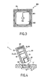
- the figure 3 illustrates the general structure of transponders 30, 40 and 50 which are used in the present invention.
- a transponder 100 is formed of a substrate 101 on which are disposed an electronic chip 102 and an antenna 103.
- the antenna 103 is formed by a coil which extends over the entire periphery of the substrate. One end of this winding is connected to the chip 102.
- the chip 102 mainly comprises an electronic data storage circuit which can be accessed in reading as well as in writing, as the case may be.
- Each transponder initially contains a unique permanent code which constitutes the identity of the transponder and which can not be modified.
- the reading, and possibly the writing, of data in the memory circuit is carried out by radiofrequency transmission thanks to the antenna 103 in particular. If the winding which constitutes the antenna 103 is interrupted, it becomes inoperative and no transmission between the chip 102 and the outside can no longer be performed, thus testifying to the damage of the component 100.
- transponder model described is passive type, ie the antenna serves not only for the transmission of data but also to receive an activation field for the supply of electrical energy to the electronic circuit of the chip. It is also possible to use transponders which comprise an autonomous power supply means, such as a battery, which battery is connected to the chip 102 to supply power.
- an autonomous power supply means such as a battery
- transponder The type of transponder described above is particularly suitable for the present invention. Indeed, such components have a very small footprint which allows them to be easily housed in sealed devices such as that of the invention.
- the substrate of the component is made of a brittle material such as silicon, it can be broken easily and thus allow the destruction of the component or at least the antenna of the latter with little resistance.
- the shape, dimensions and material of the substrate can be adapted as described below.
- a flexible material is preferably chosen which facilitates the positioning of the transponder on the rod.
- the transponder represented figure 3 has the shape of a square. However, as regards transponders 30 and 50 in particular, these could also have a circular shape to facilitate their integration into the socket.
- the permanent transponder 30 is used to store all the relevant information that will make it possible to identify the object whose closure has been marked with the sealing device of the invention.
- the object in question can be a container for transporting goods.
- the information recorded in the transponder 30 may correspond to the date and place of loading and closing of the container, the nature of the goods transported, the various customs inspections carried out, the names or the identification of the parties responsible for such inspections, ....
- the transponder 40 which is disposed on the rod 12 of the spindle 10 is used as a witness of the integrity of the sealing device. Indeed, as illustrated on the figure 4 any attempt to open the sealed object, causes the rupture of the seal device 1 and that of the transponder 40 which can not, therefore, be questioned.
- two solutions can be considered. The first is to repair the cut stem and reposition it in the seal device. The second solution is to completely replace the seal device with a new one. In both cases, unauthorized manipulation can be detected.
- the fraudulent manipulation will be detected from the next interrogation which will reveal that the transponder 40 does not respond and that, therefore, the device seal has been violated.
- the reading will reveal that the identification code of the transponder has changed and that it does not correspond to that originally recorded.
- the transponder 50 is used as a witness for the proper installation of the sealing device. Indeed, as illustrated on the figure 1 , the transponder 50 is held inside the bushing 20 at a depth P 'which is less than the height H of the rod 12 of the spindle 10 corresponding to the penetration distance of the rod into the bushing. Therefore, as illustrated on the Figure 5A when inserting the bushing 20 on the spindle 10, the end 14 of the rod 12 will abut on the transponder 50. Consequently, to bring the bushing to its final position, that is to say in the position where the ring 24 is blocked in the groove 13 of the rod, it will break the transponder 50.
- the transponder 50 is in two pieces 50A and 50B.
- the piece 50A corresponds to the part of the transponder which has been detached by the rod 12 while the piece 50B corresponds to the part which is retained between the body of the sleeve 21 and the strut holder 26. It must be ensured that the 26 which holds the piece 50A of the transponder 50 covers at least a sufficient portion of the transponder to ensure the destruction of the transponder.
- the flange 26 covers at least a portion of the antenna 103 to ensure the rupture of the latter during the installation of the device.
- the transponder 50 responds to a remote interrogation, it means that it is intact and that the bushing is not correctly positioned on the spindle.
- the reading and / or recording of data in the transponders can be carried out for example by means of a radiofrequency transmission device 60 represented in FIG. figure 2 .
- the transmission between the device 60 and the transponders is effected by radiofrequency signals RFin and RFout which respectively correspond to the signals received and to the signals sent by the device 60.
- radiofrequency signals RFin and RFout which respectively correspond to the signals received and to the signals sent by the device 60.
- the device 60 may be a portable reader that makes it possible to read and write data in a transponder.
- a reader comprises a display screen 61, a keyboard 62 and / or storage means of the interrogated data.
- the reader activates the radio frequency (RF) transponder, for example at a frequency of 13.56 MHz.
- RF radio frequency
- This wave charges a capacitance present in the circuit of the transponder. When the latter discharges, it sends back to the reader a code or information, stored in the transponder memory.
- This type of portable reader makes it possible to exchange data with the transponders over a distance of about 30 cm.
- each interrogated transponder is thus sent to the device 60.
- these data can be displayed on its screen 61 and / or stored in its memory.
- the device 60 may also include integrated processing means specially programmed to perform the checks described herein.
- processing means such as a computer 70, may be used to process the transponder data.
- the computer is connected to the device 60, via a serial link 67, to be able to exchange data with each transponder memory.
- the processing means comprise and execute software that makes it possible to perform all kinds of control and monitoring functions from the transponder data.
- the device 60 or the computer 70 may comprise software means for initially controlling the installation of the device by interrogating the transponder 50.
- the breaking information of the transponder 50 which therefore testifies to the installation correct sealing device, can be used as starting information by the processing means for, for example, store the identification codes of one or more transponders for future checks.
- the software can also make it possible to establish the correlation between the identification number of one of the transponders and various data such as the place, and / or the name of the inspector who installed the seal, and / or the date of installation of the seal.
- the software can also be used to write or update data in transponders (with the exception of the identification code which can not be modified).
- Information such as identification codes
- a database 80 ( figure 2 ) which can be accessed online, via a network link 78 such as an Internet link for example.
- the transmitting device 60, the computer 70 and the database 80 constitute a system which makes it possible to control and follow in real time any object which is marked by one or more sealing devices of the invention. This allows a tracking and a control of the goods throughout its transport. The integrity of the device can be controlled at any time. Indeed, the interrogation of the transponder 40 makes it possible to determine in a first time whether the latter is intact and, if necessary, to compare the code read in the latter with the code originally recorded in the database 80 which can be accessed remotely via network link 78.
- the permanent transponder 30 which can contain all kinds of information enriched during the steps of the transport of the object, thus constitutes the history of the seal device which can be accessed in real time by interrogating the transponder 30 at a location control.
- the sealing device according to the invention fulfills the same requirements. Its applications can be multiple.
- a plurality of devices 1 are used to mark the closing of a lid 2 on an enclosure 3.
- the elements 5 and 6 correspond to flanges in which passage openings of the devices 1 are provided. The integrity of the system thus formed is guaranteed and can be easily controlled as described above.
- the seal according to the invention has the following advantages.
- the installation of the sealing device can be validated by interrogating a transponder.
- the sealed object and its goods can be tracked throughout the transport by transponder interrogation and transmission of information. Indeed, the information, such as identification codes, can be read as many times as necessary since this is done without dismantling or tampering with the sealed device and, therefore, without compromising its integrity.
- the integrity of the device can be checked anywhere, either directly when the transponder is no longer responding, or by comparison with the identification code (s) read on site and compared with those originally recorded in an accessible database. online when the device has been replaced without authorization. It is then possible, by analysis of the data recorded in the permanent transponder, to possibly determine the person responsible, the place and the date of the unauthorized manipulation.
- the transponder circuit comprises programmable or encryptable means, it is possible to encode or encrypt the data stored in the seal, resulting in an increased level of security.
- the sealing device has a low manufacturing cost.
- the seal device has a good mechanical robustness that allows it to be used with transport objects such as containers that are often handled without special precautions.
Landscapes
- Engineering & Computer Science (AREA)
- Physics & Mathematics (AREA)
- General Physics & Mathematics (AREA)
- Theoretical Computer Science (AREA)
- Microelectronics & Electronic Packaging (AREA)
- Computer Hardware Design (AREA)
- Computer Security & Cryptography (AREA)
- General Engineering & Computer Science (AREA)
- Computer Vision & Pattern Recognition (AREA)
- Artificial Intelligence (AREA)
- Mechanical Engineering (AREA)
- Radar Systems Or Details Thereof (AREA)
- Details Of Aerials (AREA)
- Arrangements For Transmission Of Measured Signals (AREA)
- Details Of Rigid Or Semi-Rigid Containers (AREA)
- Burglar Alarm Systems (AREA)
- Seal Device For Vehicle (AREA)
- Gasket Seals (AREA)
Claims (11)
- Versiegelungsvorrichtung (1) mit einem ersten Versiegelungselement, einem zweiten Versiegelungselement und einem Mittel, um das erste Versiegelungselement an dem zweiten Versiegelungselement zu verriegeln,- wobei die Versiegelungsvorrichtung ferner einen zwischen dem ersten Versiegelungselement und dem zweiten Versiegelungselement angeordneten Transponder umfasst,- wobei der Transponder ein Substrat (101) umfasst, auf dem eine elektronische Schaltung (102) und eine Antenne (103) gebildet sind,- wobei die elektronische Schaltung Speichermittel umfasst, um mindestens einen eindeutigen Identifizierungscode zu speichern,- wobei der Transponder derart ausgelegt und angeordnet ist, dass die elektronische Schaltung (102) oder die Antenne (103) bei einem Versuch, die Versiegelungsvorrichtung zu öffnen, gebrochen werden,dadurch gekennzeichnet, dass- das zweite Versiegelungselement eine Hülse (20) ist,- das erste Versiegelungselement ein Verriegelungsbolzen (10) ist,- wobei der Verriegelungsbolzen einen Kopf (11) und einen Schaft (12) mit einem Mittel zur Verriegelung der Hülse an dem Bolzen umfasst ,- der Verriegelungsbolzen den Transponder umfasst, bei dem es sich um einen zweiten Transponder (40) handelt, der auf dem Außenumfang des Schafts (12) angeordnet ist,- die Hülse (20) einen ersten Transponder (30) umfasst, der innerhalb der Hülse in einer Tiefe (P) gelagert ist, die größer ist als die Höhe (H) des Schafts (12),- der erste und der zweite Transponder (30, 40) jeweils ein Substrat (101) umfassen, auf dem jeweils eine elektronische Schaltung (102) und eine Antenne (103) gebildet sind, wobei die elektronische Schaltung Speichermittel umfasst, um mindestens einen eindeutigen Identifizierungscode zu speichern,- der zweite Transponder (40) derart ausgelegt und angeordnet ist, dass bei einem Versuch, die Versiegelungsvorrichtung (1) zu öffnen, der Bruch der elektronischen Schaltung (102) oder der Antenne (103) des zweiten Transponders (40) bewirkt wird
- Vorrichtung nach Anspruch 1, dadurch gekennzeichnet, dass der Schaft (12) eine Kehle (13) aufweist, die mit einem Arretierring (24) zusammenwirkt, der in der Hülse (20) angeordnet ist, um durch Einführen die Hülse an dem Bolzen zu verriegeln
- Vorrichtung nach Anspruch 1 oder 2, dadurch gekennzeichnet, dass die Hülse (20) ferner einen dritten Transponder (50) umfasst, der innerhalb dieser in einer Tiefe (P') gehaltert ist, die geringer ist als die Höhe (H) des Schafts, wobei der Transponder ein Substrat (101) umfasst, auf dem eine elektronische Schaltung (102) und eine Antenne (103) gebildet sind, wobei die elektronische Schaltung Speichermittel umfasst, um mindestens einen eindeutigen Identifizierungscode zu speichern,
- Vorrichtung nach Anspruch 3, dadurch gekennzeichnet, dass der dritte Transponder (50) in der Hülse (20) durch ein ringförmiges Element (26) gehaltert ist, das mindestens die Antenne (103) des dritten Transponders (50) abdeckt
- Vorrichtung nach einem der Ansprüche 1 bis 4, dadurch gekennzeichnet, dass die Speichermittel des ersten Transponders (30) Daten über das Datum und den Ort der Anbringung der Versiegelungsvorrichtung enthalten
- Vorrichtung nach einem der Ansprüche 1 bis 5, dadurch gekennzeichnet, dass die Speichermittel des ersten Transponders Mittel zur Verschlüsselung der Daten umfassen
- System zur Kontrolle und Überwachung eines Gegenstandes, wobei der Gegenstand mindestens eine Versiegelungsvorrichtung nach einem der Ansprüche 1 bis 6 umfasst, dadurch gekennzeichnet, dass das System den Gegenstand und eine Vorrichtung zur Übertragung von Signalen (60), um Informationen aus den Transpondern bzw in die Transponder der Versiegelungsvorrichtung zu lesen oder zu schreiben, Mittel zur Verarbeitung (70) und Mittel zum Speichern von Daten (80), um die in den Transpondern gespeicherten Informationen aufzunehmen, umfasst.
- System nach Anspruch 7, dadurch gekennzeichnet, dass die Datenspeichermittel (80) über eine Netzwerkverbindung (78) fernzugänglich sind
- System nach Anspruch 7 oder 8, dadurch gekennzeichnet, dass die Verarbeitungsmittel ein Softwaremittel umfassen, um die Installation der Versiegelungsvorrichtung (1) durch Abfrage des dritten Transponders (50) zu bestätigen.
- System nach einem der Ansprüche 7 bis 9, dadurch gekennzeichnet, dass die Verarbeitungsmittel ein Softwaremittel umfassen, um eine unberechtigte Handhabung der Versiegelungsvorrichtung durch Abfrage des zweiten Transponders (40) zu erfassen.
- System nach einem der Ansprüche 7 bis 10, dadurch gekennzeichnet, dass die Verarbeitungsmittel ein Softwaremittel umfassen, um einen unberechtigten Austausch der Versiegelungsvorrichtung durch Lesen der Codes der Transponder der Versiegelungsvorrichtung (1) und durch Vergleichen der Codes mit den zuvor in die Datenspeichermittel (80) aufgenommenen Codes zu erfassen
Priority Applications (1)
| Application Number | Priority Date | Filing Date | Title |
|---|---|---|---|
| EP04711382A EP1599832B1 (de) | 2003-02-24 | 2004-02-16 | Vorrichtung zur versiegelung mit mehreren transpondern |
Applications Claiming Priority (4)
| Application Number | Priority Date | Filing Date | Title |
|---|---|---|---|
| EP03290437A EP1450300A1 (de) | 2003-02-24 | 2003-02-24 | Vorrichtung zur Versiegelung mit mehreren Transpondern |
| EP03290437 | 2003-02-24 | ||
| PCT/EP2004/050140 WO2004075102A1 (fr) | 2003-02-24 | 2004-02-16 | Dispositif de scelle a transpondeur multiple |
| EP04711382A EP1599832B1 (de) | 2003-02-24 | 2004-02-16 | Vorrichtung zur versiegelung mit mehreren transpondern |
Publications (2)
| Publication Number | Publication Date |
|---|---|
| EP1599832A1 EP1599832A1 (de) | 2005-11-30 |
| EP1599832B1 true EP1599832B1 (de) | 2008-04-09 |
Family
ID=32731618
Family Applications (2)
| Application Number | Title | Priority Date | Filing Date |
|---|---|---|---|
| EP03290437A Withdrawn EP1450300A1 (de) | 2003-02-24 | 2003-02-24 | Vorrichtung zur Versiegelung mit mehreren Transpondern |
| EP04711382A Expired - Lifetime EP1599832B1 (de) | 2003-02-24 | 2004-02-16 | Vorrichtung zur versiegelung mit mehreren transpondern |
Family Applications Before (1)
| Application Number | Title | Priority Date | Filing Date |
|---|---|---|---|
| EP03290437A Withdrawn EP1450300A1 (de) | 2003-02-24 | 2003-02-24 | Vorrichtung zur Versiegelung mit mehreren Transpondern |
Country Status (8)
| Country | Link |
|---|---|
| EP (2) | EP1450300A1 (de) |
| CN (1) | CN100495432C (de) |
| AT (1) | ATE391966T1 (de) |
| CA (1) | CA2516844C (de) |
| DE (1) | DE602004012982T2 (de) |
| DK (1) | DK1599832T3 (de) |
| ES (1) | ES2303053T3 (de) |
| WO (1) | WO2004075102A1 (de) |
Families Citing this family (9)
| Publication number | Priority date | Publication date | Assignee | Title |
|---|---|---|---|---|
| ZA200402317B (en) | 2003-09-15 | 2004-10-07 | Andrew Gerald Lynn Brown | "A seal". |
| JP3910185B2 (ja) * | 2004-03-31 | 2007-04-25 | 東芝テック株式会社 | タグユニット読取り装置 |
| WO2006107082A2 (en) | 2005-04-01 | 2006-10-12 | Daikin Industries, Ltd. | Surface modifier and its use |
| US7400247B2 (en) * | 2005-11-04 | 2008-07-15 | Motorola, Inc. | Asset seal device and method |
| FR2901242B1 (fr) * | 2006-05-17 | 2009-02-20 | Airbus Sas | Dispositif de verrouillage d'un element mobile d'un aeronef |
| CN101494009A (zh) * | 2008-01-24 | 2009-07-29 | 上海英颁斯物流科技有限公司 | 一种识别容器被开启的装置及其方法 |
| ITMI20120776A1 (it) * | 2012-05-08 | 2013-11-09 | Stema Srl | Spina marcatrice per identificare pezzi da lavorare, procedimento per tracciare pezzi da lavorare con tale spina e impianto di lavorazione che utilizza tale spina |
| DE102016010916A1 (de) * | 2016-09-08 | 2018-03-08 | Giesecke+Devrient Mobile Security Gmbh | Sicherheitssiegel |
| WO2021144035A1 (de) * | 2020-01-17 | 2021-07-22 | Stoba Ag | Verfahren zum ausgeben eines zustands von mindestens einem siegel, siegel und system |
Family Cites Families (4)
| Publication number | Priority date | Publication date | Assignee | Title |
|---|---|---|---|---|
| ATE136674T1 (de) * | 1991-12-19 | 1996-04-15 | Ake Gustafson | Sicherheitsverschliessvorrichtung |
| DE19709364C2 (de) * | 1997-03-07 | 1998-12-24 | Diehl Ident Gmbh | Plombe für ein geteiltes Gehäuse |
| DE69937794T2 (de) * | 1999-09-15 | 2009-04-30 | European Community | Elektronisches Mehrwegsiegel mit passivem Transponder |
| DE29920189U1 (de) * | 1999-11-17 | 2000-05-11 | Hundhausen, Albrecht, Dr.-Ing., 64372 Ober-Ramstadt | Elektronische Schraubenplombe |
-
2003
- 2003-02-24 EP EP03290437A patent/EP1450300A1/de not_active Withdrawn
-
2004
- 2004-02-16 DE DE602004012982T patent/DE602004012982T2/de not_active Expired - Lifetime
- 2004-02-16 CN CNB2004800077224A patent/CN100495432C/zh not_active Expired - Fee Related
- 2004-02-16 ES ES04711382T patent/ES2303053T3/es not_active Expired - Lifetime
- 2004-02-16 WO PCT/EP2004/050140 patent/WO2004075102A1/fr active IP Right Grant
- 2004-02-16 EP EP04711382A patent/EP1599832B1/de not_active Expired - Lifetime
- 2004-02-16 AT AT04711382T patent/ATE391966T1/de active
- 2004-02-16 DK DK04711382T patent/DK1599832T3/da active
- 2004-02-16 CA CA2516844A patent/CA2516844C/fr not_active Expired - Fee Related
Also Published As
| Publication number | Publication date |
|---|---|
| ES2303053T3 (es) | 2008-08-01 |
| CN100495432C (zh) | 2009-06-03 |
| DK1599832T3 (da) | 2008-07-07 |
| EP1599832A1 (de) | 2005-11-30 |
| CA2516844C (fr) | 2012-09-25 |
| DE602004012982D1 (de) | 2008-05-21 |
| WO2004075102A1 (fr) | 2004-09-02 |
| CA2516844A1 (fr) | 2004-09-02 |
| EP1450300A1 (de) | 2004-08-25 |
| CN1768348A (zh) | 2006-05-03 |
| DE602004012982T2 (de) | 2009-04-02 |
| ATE391966T1 (de) | 2008-04-15 |
Similar Documents
| Publication | Publication Date | Title |
|---|---|---|
| EP2794199B1 (de) | Einrichtung mit einem handschuhfach und handschuhwechselvorrichtung mit überwachung des handschuhwechsels | |
| EP1556622B1 (de) | Befestigungsglied mit einem system zur kontrolle der unversehrtheit | |
| EP1511909B9 (de) | Mehrzwecksiegel mit einem schloss und verfahren zur herstellung eines mehrzwecksiegels | |
| US20060152366A1 (en) | Multiple transponder seal device | |
| CA2494401C (fr) | Emballage a integrite controlable | |
| EP1599832B1 (de) | Vorrichtung zur versiegelung mit mehreren transpondern | |
| EP3248147B1 (de) | Authentifizierung einer flasche und deren inhalts | |
| EP3667000B1 (de) | Steuersystem und -verfahren der entriegelung einer schutzvorrichtung gegen diebstahl eines verpackten oder unverpackten handelsartikels | |
| EP1087334B1 (de) | Mehrwegelektronisches Siegel mittels eines passiven Transponders | |
| EP2136849B1 (de) | Medizinische bildgebungsvorrichtung mit einem gehäuse zur dekontamination und identifikation eines medizinischen gerätes | |
| EP4121902B1 (de) | Verpackung mit einer radiofrequenz-identifizierungsdichtung | |
| WO2020025882A1 (fr) | Système de contrôle de pièces d'un turboréacteur par identification radiofréquence | |
| EP1766587A1 (de) | Sicheres transportverfahren für wertdokumente und wertgegenstände sowie behälter zur ausführung dieses verfahrens | |
| SE545584C2 (en) | A sample holding device, a system, and a method for securing non-tampering of a sample | |
| FR2863745A1 (fr) | Memoire pour etiquettes rfid adaptee pour recevoir une commande de desactivation | |
| FR3108428A1 (fr) | Système d’acheminement d’un objet par un colis primaire identification de l’objet et affichage sur le colis primaire d’un label correspondant à l’objet identifié | |
| EP3479366B1 (de) | Verfahren zur überwachung der öffnung eines behälters | |
| FR3089660A1 (fr) | Appareil et systeme d'identification d'objets dans un local | |
| FR2821463A1 (fr) | Dispositif d'authentification de plaques mineralogiques | |
| EP0658864A1 (de) | Markierungsvorrichtung | |
| FR3122755A3 (fr) | Dispositif a collier pour la traçabilité des bouteilles | |
| EP1230630B1 (de) | Vorrichtung zum erkennen und identifizieren der bewegung eines gegenstandes | |
| WO2022223331A1 (fr) | Colis comprenant un scellé | |
| WO1996038824A1 (fr) | Dispositif pour le rangement de petits objets et pour la gestion et la surveillance des entrees et sorties de ces petits objets | |
| WO2007031644A1 (fr) | Dispositif d'encapsulement d'une pluralité d'étiquette d'identification électronique |
Legal Events
| Date | Code | Title | Description |
|---|---|---|---|
| PUAI | Public reference made under article 153(3) epc to a published international application that has entered the european phase |
Free format text: ORIGINAL CODE: 0009012 |
|
| 17P | Request for examination filed |
Effective date: 20050804 |
|
| AK | Designated contracting states |
Kind code of ref document: A1 Designated state(s): AT BE BG CH CY CZ DE DK EE ES FI FR GB GR HU IE IT LI LU MC NL PT RO SE SI SK TR |
|
| AX | Request for extension of the european patent |
Extension state: AL LT LV MK |
|
| DAX | Request for extension of the european patent (deleted) | ||
| RIN1 | Information on inventor provided before grant (corrected) |
Inventor name: KORN, CHRISTOPHE Inventor name: TEBALDI, PIERCARLO Inventor name: SIRONI, MARCO Inventor name: POUCET, ANDRE |
|
| 17Q | First examination report despatched |
Effective date: 20051121 |
|
| GRAP | Despatch of communication of intention to grant a patent |
Free format text: ORIGINAL CODE: EPIDOSNIGR1 |
|
| GRAS | Grant fee paid |
Free format text: ORIGINAL CODE: EPIDOSNIGR3 |
|
| GRAA | (expected) grant |
Free format text: ORIGINAL CODE: 0009210 |
|
| AK | Designated contracting states |
Kind code of ref document: B1 Designated state(s): AT BE BG CH CY CZ DE DK EE ES FI FR GB GR HU IE IT LI LU MC NL PT RO SE SI SK TR |
|
| REG | Reference to a national code |
Ref country code: GB Ref legal event code: FG4D Free format text: NOT ENGLISH |
|
| REG | Reference to a national code |
Ref country code: CH Ref legal event code: EP |
|
| REG | Reference to a national code |
Ref country code: IE Ref legal event code: FG4D Free format text: LANGUAGE OF EP DOCUMENT: FRENCH |
|
| REF | Corresponds to: |
Ref document number: 602004012982 Country of ref document: DE Date of ref document: 20080521 Kind code of ref document: P |
|
| REG | Reference to a national code |
Ref country code: CH Ref legal event code: NV Representative=s name: WILLIAM BLANC & CIE CONSEILS EN PROPRIETE INDUSTRI |
|
| REG | Reference to a national code |
Ref country code: DK Ref legal event code: T3 |
|
| REG | Reference to a national code |
Ref country code: SE Ref legal event code: TRGR |
|
| REG | Reference to a national code |
Ref country code: ES Ref legal event code: FG2A Ref document number: 2303053 Country of ref document: ES Kind code of ref document: T3 |
|
| PG25 | Lapsed in a contracting state [announced via postgrant information from national office to epo] |
Ref country code: SI Free format text: LAPSE BECAUSE OF FAILURE TO SUBMIT A TRANSLATION OF THE DESCRIPTION OR TO PAY THE FEE WITHIN THE PRESCRIBED TIME-LIMIT Effective date: 20080409 |
|
| PG25 | Lapsed in a contracting state [announced via postgrant information from national office to epo] |
Ref country code: PT Free format text: LAPSE BECAUSE OF FAILURE TO SUBMIT A TRANSLATION OF THE DESCRIPTION OR TO PAY THE FEE WITHIN THE PRESCRIBED TIME-LIMIT Effective date: 20080910 Ref country code: BG Free format text: LAPSE BECAUSE OF FAILURE TO SUBMIT A TRANSLATION OF THE DESCRIPTION OR TO PAY THE FEE WITHIN THE PRESCRIBED TIME-LIMIT Effective date: 20080709 |
|
| PG25 | Lapsed in a contracting state [announced via postgrant information from national office to epo] |
Ref country code: CZ Free format text: LAPSE BECAUSE OF FAILURE TO SUBMIT A TRANSLATION OF THE DESCRIPTION OR TO PAY THE FEE WITHIN THE PRESCRIBED TIME-LIMIT Effective date: 20080409 |
|
| PLBE | No opposition filed within time limit |
Free format text: ORIGINAL CODE: 0009261 |
|
| STAA | Information on the status of an ep patent application or granted ep patent |
Free format text: STATUS: NO OPPOSITION FILED WITHIN TIME LIMIT |
|
| PG25 | Lapsed in a contracting state [announced via postgrant information from national office to epo] |
Ref country code: RO Free format text: LAPSE BECAUSE OF FAILURE TO SUBMIT A TRANSLATION OF THE DESCRIPTION OR TO PAY THE FEE WITHIN THE PRESCRIBED TIME-LIMIT Effective date: 20080409 Ref country code: SK Free format text: LAPSE BECAUSE OF FAILURE TO SUBMIT A TRANSLATION OF THE DESCRIPTION OR TO PAY THE FEE WITHIN THE PRESCRIBED TIME-LIMIT Effective date: 20080409 |
|
| 26N | No opposition filed |
Effective date: 20090112 |
|
| PG25 | Lapsed in a contracting state [announced via postgrant information from national office to epo] |
Ref country code: EE Free format text: LAPSE BECAUSE OF FAILURE TO SUBMIT A TRANSLATION OF THE DESCRIPTION OR TO PAY THE FEE WITHIN THE PRESCRIBED TIME-LIMIT Effective date: 20080409 |
|
| PG25 | Lapsed in a contracting state [announced via postgrant information from national office to epo] |
Ref country code: MC Free format text: LAPSE BECAUSE OF NON-PAYMENT OF DUE FEES Effective date: 20090228 Ref country code: CY Free format text: LAPSE BECAUSE OF FAILURE TO SUBMIT A TRANSLATION OF THE DESCRIPTION OR TO PAY THE FEE WITHIN THE PRESCRIBED TIME-LIMIT Effective date: 20080409 |
|
| REG | Reference to a national code |
Ref country code: CH Ref legal event code: PFA Owner name: THE EUROPEAN COMMUNITY, REPRESENTED BY THE EUROPE Free format text: THE EUROPEAN COMMUNITY, REPRESENTED BY THE EUROPEAN COMMISSION#200, RUE DE LA LOI#1049 BRUSSELS (BE) -TRANSFER TO- THE EUROPEAN COMMUNITY, REPRESENTED BY THE EUROPEAN COMMISSION#200, RUE DE LA LOI#1049 BRUSSELS (BE) |
|
| PG25 | Lapsed in a contracting state [announced via postgrant information from national office to epo] |
Ref country code: GR Free format text: LAPSE BECAUSE OF FAILURE TO SUBMIT A TRANSLATION OF THE DESCRIPTION OR TO PAY THE FEE WITHIN THE PRESCRIBED TIME-LIMIT Effective date: 20080710 |
|
| REG | Reference to a national code |
Ref country code: FR Ref legal event code: CD |
|
| REG | Reference to a national code |
Ref country code: DE Ref legal event code: R081 Ref document number: 602004012982 Country of ref document: DE Owner name: EUROPEAN UNION, BE Free format text: FORMER OWNER: THE EUROPEAN COMMUNITY, REPRESENTED BY THE EUROPEAN COMMISSION, BRUESSEL/BRUXELLES, BE Effective date: 20110208 |
|
| PG25 | Lapsed in a contracting state [announced via postgrant information from national office to epo] |
Ref country code: LU Free format text: LAPSE BECAUSE OF NON-PAYMENT OF DUE FEES Effective date: 20090216 |
|
| PG25 | Lapsed in a contracting state [announced via postgrant information from national office to epo] |
Ref country code: HU Free format text: LAPSE BECAUSE OF FAILURE TO SUBMIT A TRANSLATION OF THE DESCRIPTION OR TO PAY THE FEE WITHIN THE PRESCRIBED TIME-LIMIT Effective date: 20081010 |
|
| REG | Reference to a national code |
Ref country code: CH Ref legal event code: PCAR Free format text: NOVAGRAAF SWITZERLAND SA;CHEMIN DE L'ECHO 3;1213 ONEX (CH) |
|
| PG25 | Lapsed in a contracting state [announced via postgrant information from national office to epo] |
Ref country code: TR Free format text: LAPSE BECAUSE OF FAILURE TO SUBMIT A TRANSLATION OF THE DESCRIPTION OR TO PAY THE FEE WITHIN THE PRESCRIBED TIME-LIMIT Effective date: 20080409 |
|
| REG | Reference to a national code |
Ref country code: FR Ref legal event code: PLFP Year of fee payment: 13 |
|
| REG | Reference to a national code |
Ref country code: FR Ref legal event code: PLFP Year of fee payment: 14 |
|
| PGFP | Annual fee paid to national office [announced via postgrant information from national office to epo] |
Ref country code: NL Payment date: 20170123 Year of fee payment: 14 |
|
| PGFP | Annual fee paid to national office [announced via postgrant information from national office to epo] |
Ref country code: CH Payment date: 20170125 Year of fee payment: 14 Ref country code: DE Payment date: 20170119 Year of fee payment: 14 Ref country code: FR Payment date: 20170124 Year of fee payment: 14 Ref country code: SE Payment date: 20170124 Year of fee payment: 14 Ref country code: FI Payment date: 20170120 Year of fee payment: 14 |
|
| PGFP | Annual fee paid to national office [announced via postgrant information from national office to epo] |
Ref country code: BE Payment date: 20170119 Year of fee payment: 14 Ref country code: DK Payment date: 20170120 Year of fee payment: 14 Ref country code: GB Payment date: 20170124 Year of fee payment: 14 Ref country code: IE Payment date: 20170123 Year of fee payment: 14 Ref country code: AT Payment date: 20170120 Year of fee payment: 14 |
|
| PGFP | Annual fee paid to national office [announced via postgrant information from national office to epo] |
Ref country code: IT Payment date: 20170120 Year of fee payment: 14 Ref country code: ES Payment date: 20170123 Year of fee payment: 14 |
|
| REG | Reference to a national code |
Ref country code: DE Ref legal event code: R119 Ref document number: 602004012982 Country of ref document: DE |
|
| REG | Reference to a national code |
Ref country code: CH Ref legal event code: PL |
|
| REG | Reference to a national code |
Ref country code: DK Ref legal event code: EBP Effective date: 20180228 |
|
| REG | Reference to a national code |
Ref country code: SE Ref legal event code: EUG |
|
| REG | Reference to a national code |
Ref country code: NL Ref legal event code: MM Effective date: 20180301 |
|
| REG | Reference to a national code |
Ref country code: AT Ref legal event code: MM01 Ref document number: 391966 Country of ref document: AT Kind code of ref document: T Effective date: 20180216 |
|
| GBPC | Gb: european patent ceased through non-payment of renewal fee |
Effective date: 20180216 |
|
| PG25 | Lapsed in a contracting state [announced via postgrant information from national office to epo] |
Ref country code: SE Free format text: LAPSE BECAUSE OF NON-PAYMENT OF DUE FEES Effective date: 20180217 Ref country code: FI Free format text: LAPSE BECAUSE OF NON-PAYMENT OF DUE FEES Effective date: 20180216 |
|
| REG | Reference to a national code |
Ref country code: IE Ref legal event code: MM4A |
|
| REG | Reference to a national code |
Ref country code: BE Ref legal event code: MM Effective date: 20180228 |
|
| PG25 | Lapsed in a contracting state [announced via postgrant information from national office to epo] |
Ref country code: AT Free format text: LAPSE BECAUSE OF NON-PAYMENT OF DUE FEES Effective date: 20180216 Ref country code: LI Free format text: LAPSE BECAUSE OF NON-PAYMENT OF DUE FEES Effective date: 20180228 Ref country code: CH Free format text: LAPSE BECAUSE OF NON-PAYMENT OF DUE FEES Effective date: 20180228 |
|
| REG | Reference to a national code |
Ref country code: FR Ref legal event code: ST Effective date: 20181031 |
|
| PG25 | Lapsed in a contracting state [announced via postgrant information from national office to epo] |
Ref country code: NL Free format text: LAPSE BECAUSE OF NON-PAYMENT OF DUE FEES Effective date: 20180301 |
|
| PG25 | Lapsed in a contracting state [announced via postgrant information from national office to epo] |
Ref country code: DE Free format text: LAPSE BECAUSE OF NON-PAYMENT OF DUE FEES Effective date: 20180901 Ref country code: IE Free format text: LAPSE BECAUSE OF NON-PAYMENT OF DUE FEES Effective date: 20180216 Ref country code: DK Free format text: LAPSE BECAUSE OF NON-PAYMENT OF DUE FEES Effective date: 20180228 |
|
| PG25 | Lapsed in a contracting state [announced via postgrant information from national office to epo] |
Ref country code: IT Free format text: LAPSE BECAUSE OF NON-PAYMENT OF DUE FEES Effective date: 20180216 Ref country code: BE Free format text: LAPSE BECAUSE OF NON-PAYMENT OF DUE FEES Effective date: 20180228 Ref country code: GB Free format text: LAPSE BECAUSE OF NON-PAYMENT OF DUE FEES Effective date: 20180216 Ref country code: FR Free format text: LAPSE BECAUSE OF NON-PAYMENT OF DUE FEES Effective date: 20180228 |
|
| REG | Reference to a national code |
Ref country code: ES Ref legal event code: FD2A Effective date: 20190801 |
|
| PG25 | Lapsed in a contracting state [announced via postgrant information from national office to epo] |
Ref country code: ES Free format text: LAPSE BECAUSE OF NON-PAYMENT OF DUE FEES Effective date: 20180217 |