EP1511646B1 - Elektrisch angetriebenes fahrzeug mit einzelradantrieb - Google Patents
Elektrisch angetriebenes fahrzeug mit einzelradantrieb Download PDFInfo
- Publication number
- EP1511646B1 EP1511646B1 EP03732535A EP03732535A EP1511646B1 EP 1511646 B1 EP1511646 B1 EP 1511646B1 EP 03732535 A EP03732535 A EP 03732535A EP 03732535 A EP03732535 A EP 03732535A EP 1511646 B1 EP1511646 B1 EP 1511646B1
- Authority
- EP
- European Patent Office
- Prior art keywords
- vehicle
- drive
- drive motor
- driving wheel
- pan
- Prior art date
- Legal status (The legal status is an assumption and is not a legal conclusion. Google has not performed a legal analysis and makes no representation as to the accuracy of the status listed.)
- Expired - Lifetime
Links
- 230000005540 biological transmission Effects 0.000 claims description 19
- XLYOFNOQVPJJNP-UHFFFAOYSA-N water Substances O XLYOFNOQVPJJNP-UHFFFAOYSA-N 0.000 claims description 8
- 230000009351 contact transmission Effects 0.000 claims 1
- 238000007789 sealing Methods 0.000 claims 1
- 238000009434 installation Methods 0.000 description 3
- 230000007613 environmental effect Effects 0.000 description 2
- 230000005855 radiation Effects 0.000 description 2
- 230000006835 compression Effects 0.000 description 1
- 238000007906 compression Methods 0.000 description 1
- 238000001816 cooling Methods 0.000 description 1
- 238000013016 damping Methods 0.000 description 1
- 230000001419 dependent effect Effects 0.000 description 1
- 238000011161 development Methods 0.000 description 1
- 230000018109 developmental process Effects 0.000 description 1
- 230000001747 exhibiting effect Effects 0.000 description 1
- 238000012423 maintenance Methods 0.000 description 1
- 239000000725 suspension Substances 0.000 description 1
- 238000013519 translation Methods 0.000 description 1
- 230000014616 translation Effects 0.000 description 1
Images


Classifications
-
- B—PERFORMING OPERATIONS; TRANSPORTING
- B60—VEHICLES IN GENERAL
- B60K—ARRANGEMENT OR MOUNTING OF PROPULSION UNITS OR OF TRANSMISSIONS IN VEHICLES; ARRANGEMENT OR MOUNTING OF PLURAL DIVERSE PRIME-MOVERS IN VEHICLES; AUXILIARY DRIVES FOR VEHICLES; INSTRUMENTATION OR DASHBOARDS FOR VEHICLES; ARRANGEMENTS IN CONNECTION WITH COOLING, AIR INTAKE, GAS EXHAUST OR FUEL SUPPLY OF PROPULSION UNITS IN VEHICLES
- B60K7/00—Disposition of motor in, or adjacent to, traction wheel
- B60K7/0007—Disposition of motor in, or adjacent to, traction wheel the motor being electric
-
- B—PERFORMING OPERATIONS; TRANSPORTING
- B60—VEHICLES IN GENERAL
- B60K—ARRANGEMENT OR MOUNTING OF PROPULSION UNITS OR OF TRANSMISSIONS IN VEHICLES; ARRANGEMENT OR MOUNTING OF PLURAL DIVERSE PRIME-MOVERS IN VEHICLES; AUXILIARY DRIVES FOR VEHICLES; INSTRUMENTATION OR DASHBOARDS FOR VEHICLES; ARRANGEMENTS IN CONNECTION WITH COOLING, AIR INTAKE, GAS EXHAUST OR FUEL SUPPLY OF PROPULSION UNITS IN VEHICLES
- B60K17/00—Arrangement or mounting of transmissions in vehicles
- B60K17/04—Arrangement or mounting of transmissions in vehicles characterised by arrangement, location or kind of gearing
- B60K17/043—Transmission unit disposed in on near the vehicle wheel, or between the differential gear unit and the wheel
-
- B—PERFORMING OPERATIONS; TRANSPORTING
- B60—VEHICLES IN GENERAL
- B60K—ARRANGEMENT OR MOUNTING OF PROPULSION UNITS OR OF TRANSMISSIONS IN VEHICLES; ARRANGEMENT OR MOUNTING OF PLURAL DIVERSE PRIME-MOVERS IN VEHICLES; AUXILIARY DRIVES FOR VEHICLES; INSTRUMENTATION OR DASHBOARDS FOR VEHICLES; ARRANGEMENTS IN CONNECTION WITH COOLING, AIR INTAKE, GAS EXHAUST OR FUEL SUPPLY OF PROPULSION UNITS IN VEHICLES
- B60K7/00—Disposition of motor in, or adjacent to, traction wheel
- B60K2007/0046—Disposition of motor in, or adjacent to, traction wheel the motor moving together with the vehicle body, i.e. moving independently from the wheel axle
-
- B—PERFORMING OPERATIONS; TRANSPORTING
- B60—VEHICLES IN GENERAL
- B60K—ARRANGEMENT OR MOUNTING OF PROPULSION UNITS OR OF TRANSMISSIONS IN VEHICLES; ARRANGEMENT OR MOUNTING OF PLURAL DIVERSE PRIME-MOVERS IN VEHICLES; AUXILIARY DRIVES FOR VEHICLES; INSTRUMENTATION OR DASHBOARDS FOR VEHICLES; ARRANGEMENTS IN CONNECTION WITH COOLING, AIR INTAKE, GAS EXHAUST OR FUEL SUPPLY OF PROPULSION UNITS IN VEHICLES
- B60K7/00—Disposition of motor in, or adjacent to, traction wheel
- B60K2007/0061—Disposition of motor in, or adjacent to, traction wheel the motor axle being parallel to the wheel axle
-
- B—PERFORMING OPERATIONS; TRANSPORTING
- B60—VEHICLES IN GENERAL
- B60L—PROPULSION OF ELECTRICALLY-PROPELLED VEHICLES; SUPPLYING ELECTRIC POWER FOR AUXILIARY EQUIPMENT OF ELECTRICALLY-PROPELLED VEHICLES; ELECTRODYNAMIC BRAKE SYSTEMS FOR VEHICLES IN GENERAL; MAGNETIC SUSPENSION OR LEVITATION FOR VEHICLES; MONITORING OPERATING VARIABLES OF ELECTRICALLY-PROPELLED VEHICLES; ELECTRIC SAFETY DEVICES FOR ELECTRICALLY-PROPELLED VEHICLES
- B60L2220/00—Electrical machine types; Structures or applications thereof
- B60L2220/40—Electrical machine applications
- B60L2220/46—Wheel motors, i.e. motor connected to only one wheel
Definitions
- the invention relates to an electrically driven vehicle having a plurality of drive wheels, each associated with a drive having at least one electric motor.
- the drive motors are arranged in the vehicle chassis or in armored vehicles in the vehicle pan in the axial extension of the drive wheels.
- a disadvantage of this arrangement is that the space between the wheels is occupied by the drive motors and not otherwise used.
- the drive motors are arranged in the wheel hubs.
- the space between the drive wheels remains largely free of drive components.
- the disadvantage here is that the sprung masses in the wheel are very high, so that thermal problems occur especially at high speeds in the field on the damping elements.
- the space in the hubs is very limited, so that larger-scale electrical machines, such. B. asynchronous machines are difficult or bad to use and expensive permanent magnet motors are needed.
- With wheel hub motors it is extremely difficult to keep the drive's heat and noise emission to a minimum.
- Wat-operation complex seals on the hub are necessary. Relatively long supply and cooling lines are required, which, like the drive motor itself, are relatively poorly protected against bombardment and environmental influences.
- DE 196 17 165 A1 and EP 0 966 361 B1 show electrically driven vehicles with a chassis and a plurality of drive wheels, which each have a drive associated with at least one electric motor.
- the electric motor is arranged, at least partially, in the axial installation space occupied by the drive wheel radially outside the drive wheel.
- the drive connection of the drive motor with the drive wheel is carried out with a spur gear connecting gear, the housing is arranged on the side facing the center of the vehicle drive wheel and drive motor.
- This arrangement allows the use of larger-scale asynchronous machines, without the space between the drive wheels would be significantly restricted.
- the disadvantage of these arrangements is that the sprung masses are similar to the hub drive and that only a limited spring travel is available.
- a vehicle according to the preamble of claims 1 and 3 is known from WO 00/32462 A.
- the invention is therefore based on the object of specifying an electrically driven vehicle which is suitable for high speeds in the terrain, in which the wheels have low sprung masses and a high spring travel, a wide passage in the vehicle interior, even when using longer-lasting asynchronous Motors, possible and also suitable for steerable wheels.
- the heat and noise radiation to the outside low and the passage of shallow water should be possible.
- the housing of the connection transmission which drives the electric motor and drive wheel, and the drive motor is rigidly connected to the vehicle pan.
- a propeller shaft is provided which is connected by means of a hinge to the output of the connecting gear.
- seals are provided so that the electric motor is water-protected within the vehicle pan, and the area of the electric motor remains dry when the drive wheel is completely or partially under water.
- the housing of the connecting gear penetrates the vehicle pan, and between the vehicle pan and the housing of the connecting gear the seal is provided.
- the entire connection gear water-protected within the vehicle pan so that only the propeller shaft, which penetrates the vehicle pan, must be sealed by a seal.
- the inventive arrangement of the single-wheel drive brings no restrictions on the type of suspension with it.
- Fig. 1, 2 denotes a rear left section of a vehicle pan of a multi-axle off-road vehicle.
- the propeller shaft 8 has at its two ends joints 10, 12, which allow a compression movement and / or a steering angle of the wheel 6.
- the propeller shaft 8 is drivingly connected to the input of the Radkopfgetriebes 6.
- the propeller shaft 8 is connected to the output of the connecting gear 14, whose housing is rigidly connected to the vehicle pan 2.
- the connecting gear 14 is connected to the motor shaft 16 of the drive motor 18.
- the drive motor 18 is arranged with its directed towards the vehicle outer side partially in the space occupied by the drive wheel 4 axial space 20 radially outside the drive wheel.
- the housing of the connecting gear 14 is arranged on the side facing the center of the vehicle drive wheel 4 and drive motor 18.
- the area of the vehicle pan inside the connecting gear remains free of components of the drive, so that a wide passage in the vehicle center is created.
- the unsprung mass of the drive wheel 4 is low, since the connecting gear 14 and the drive motor 18 of the sprung vehicle pan 2 are assigned.
- a gasket 22 is provided in the area the breakthrough of the propeller shaft 8 through the vehicle pan 2.
- the drive motor 18 and the connecting gear 16 are thus arranged protected against water within the vehicle pan and remain dry, even if the drive wheel 4 is completely or partially under water.
- the vehicle trough 2 has an opening on the outside in the axial extension of the drive motor 18, so that the drive motor is accessible from outside for installation and maintenance purposes. This opening is vesch concentratedbar by a cover 24.
- the drive motor 18 and the connecting gear 14 are completely protected against environmental influences and bombardment within the armored vehicle trough 2. At this point, the unwanted heat and noise radiation to the outside is very low.
- the connecting gear 14 according to FIG. 3 is designed as a spur gear chain with an example of four specified spur gears 26, 28, 30, 32, which are rotatably mounted in the housing of the connecting gear 14.
- the connecting gear 14 can be produced with little effort in different variants with different translations, so that adjustments to the overall ratios are very easy to accomplish.
- a different number of spur gears is possible and is in a further suitable embodiment of three spur gears.
- a spur gear chain can also be used provided with a chain or belt drive belt transmission.
- a drive motor 18 and a connecting gear 14 are assigned to each wheel 4 of the vehicle.
- the drive motors 18 are each arranged in the space above the axes of rotation of the drive wheels 4 between two adjacent drive wheels in the direction of travel 34 in front of the associated drive wheel 4.
- 6 and 7 show a constellation in which the drive motors 18 each lie behind the axis of rotation of the associated drive wheel 4.
- the connecting gears 14 with the drive motors 18 of the middle, adjacent drive wheels 4 are inclined towards each other, so that the axes of rotation of the drive shafts of the drive motors lie in the horizontal direction between the axes of rotation of the drive wheels 4.
- This constellation is particularly advantageous if, for reasons of redundancy, the drive motors 18 of the adjacent drive wheels 4 are to be coupled or coupled to one another in terms of driving, as indicated in FIG. 9 by the spur gears 26, 40.
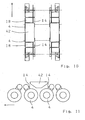
- FIGS. 10 and 11 show a constellation in which the connecting gear 14 with the drive motors 18 of two adjacent drive wheels 4 are inclined away from each other. In this way, in the area above and between the two drive wheels 4, a free space is formed, which is suitable for larger units such.
- the power supply unit 42 for the electric drive motors 18, is available. At this point, the power supply unit 42, typically consisting of a diesel engine and a generator, is well accessible from the outside through corresponding service openings, and the passageway along the center of the vehicle remains free.
Landscapes
- Engineering & Computer Science (AREA)
- Chemical & Material Sciences (AREA)
- Combustion & Propulsion (AREA)
- Transportation (AREA)
- Mechanical Engineering (AREA)
- Arrangement Or Mounting Of Propulsion Units For Vehicles (AREA)
- Automatic Cycles, And Cycles In General (AREA)
- Arrangement And Driving Of Transmission Devices (AREA)
Description
- Die Erfindung betrifft ein elektrisch angetriebenes Fahrzeug mit mehreren Antriebsrädern, denen jeweils ein Antrieb mit mindestens einem Elektromotor zugeordnet ist.
- Für Fahrzeuge mit elektrischen Einzelradantrieben existieren verschiedene Konzepte für die Anordnung der Antriebe im Fahrzeug.
- Bei einem bekannten Konzept sind die Antriebsmotoren im Fahrzeugchassis bzw. bei gepanzerten Fahrzeugen in der Fahrzeugwanne in axialer Verlängerung der Antriebsräder angeordnet. Nachteilig bei dieser Anordnung ist, dass der Raum zwischen den Rädern von den Antriebsmotoren belegt wird und nicht anderweitig nutzbar ist.
- Bei einem anderen bekannten Konzept sind die Antriebsmotoren in den Radnaben angeordnet. Dadurch bleibt der Raum zwischen den Antriebsrädern weitgehend frei von Antriebskomponenten. Nachteilig dabei ist jedoch, dass die gefederten Massen im Rad sehr hoch sind, so dass insbesondere bei hohen Geschwindigkeiten im Gelände thermische Probleme an den Dämpfungselementen auftreten. Der Bauraum in den Radnaben ist sehr begrenzt, so dass größerbauende elektrische Maschinen, wie z. B. Asynchron-Maschinen, schwer oder schlecht verwendbar sind und teure Permanentmagnetmotoren benötigt werden. Insbesondere bei militärisch genutzten Fahrzeugen kommen noch weitere nachteilige Aspekte dieses Konzepts hinzu: Bei Radnabenmotoren ist es äußerst schwierig, die Wärme- und Geräuschabstrahlung des Antriebs klein zu halten. Damit auch ein Einsatz mit teilweise unter Wasser stehenden Rädern möglich ist, ein sogenannter Wat-Betrieb, sind aufwendige Abdichtungen an der Radnabe notwendig. Es werden relativ lange Versorgungs- und Kühlleitungen benötigt, die ebenso wie der Antriebsmotor selbst relativ schlecht geschützt gegenüber Beschuß und Umwelteinflüssen sind.
- Die DE 196 17 165 A1 und die EP 0 966 361 B1 zeigen elektrisch angetriebene Fahrzeuge mit einem Chassis und mehreren Antriebsrädern, denen jeweils ein Antrieb mit mindestens einem Elektromotor zugeordnet ist. Dabei ist der Elektromotor, zumindest teilweise, in dem vom Antriebsrad eingenommenen axialen Bauraum radial außerhalb des Antriebsrads angeordnet. Die triebliche Verbindung des Antriebsmotors mit dem Antriebsrad erfolgt mit einem Stirnrad-Verbindungsgetriebe, dessen Gehäuse auf der zur Fahrzeugmitte zugewandten Seite von Antriebsrad und Antriebsmotor angeordnet ist. Diese Anordnung ermöglicht den Einsatz auch von größerbauenden Asynchron-Maschinen, ohne dass der Bauraum zwischen den Antriebsrädern wesentlich eingeschränkt würde. Der Nachteil dieser Anordnungen besteht darin, dass die gefederten Massen ähnlich hoch wie beim Radnabenantrieb sind und dass nur ein begrenzter Federweg zur Verfügung steht. Diese Konzepte sind auch nicht geeignet für gelenkte Räder, so dass sie nicht für mehrachsgetriebene Geländefahrzeuge in Frage kommen.
- Ein Fahrzeug nach dem Oberbegriff der Ansprüche 1 und 3 ist aus der WO 00/32462 A bekannt.
- Der Erfindung liegt daher die Aufgabe zugrunde, ein elektrisch angetriebenes Fahrzeug anzugeben, das für hohe Geschwindigkeiten im Gelände geeignet ist, bei dem die Räder geringe gefederte Massen und einen hohen Federweg aufweisen, das einen breiten Durchgang im Fahrzeuginnern, auch beim Einsatz von längerbauenden Asynchron-Motoren, ermöglicht und das außerdem für lenkbare Räder geeignet ist. Darüber hinaus soll die Wärme- und Geräuschabstrahlung nach außen gering und das Durchfahren von seichtem Wasser soll möglich sein.
- Diese Aufgabe wird gelöst durch ein, auch die Merkmale der kennzeichnenden Teile der Ansprüche 1 und 3 aufweisendes, elektrisch angetriebenes Fahrzeug. Vorteilhafte Weiterbildungen der Erfindung sind durch die Unteransprüche gegeben.
- Es sind also bei dem Fahrzeug, bei dem der jedem Antriebsrad zugeordnete Elektromotor zumindest teilweise in dem vom Antriebsrad eingenommenen axialen Bauraum außerhalb des Antriebsrads angeordnet ist, das Gehäuse des Verbindungsgetriebes, welches Elektromotor und Antriebsrad trieblich verbindet, und der Antriebsmotor starr mit der Fahrzeugwanne verbunden. Zwischen dem Abtrieb des Verbindungsgetriebes und dem Antriebsrad ist eine Gelenkwelle vorgesehen, die mittels eines Gelenks mit dem Abtrieb des Verbindungsgetriebes verbunden ist. Es wird eine sehr gute Bauraumausnutzung erzielt, die gefederten Massen der Antriebsräder sind sehr gering, und der Elektromotor ist geschützt innerhalb der Fahrzeugwanne angeordnet.
- In einer vorteilhaften Ausgestaltung sind Dichtungen vorgesehen, so dass der Elektromotor wassergeschützt innerhalb der Fahrzeugwanne angeordnet ist, und der Bereich des Elektromotors trocken bleibt, wenn das Antriebsrad ganz oder teilweise unter Wasser ist.
- Bei einer Variante dieser Ausgestaltung durchdringt das Gehäuse des Verbindungsgetriebes die Fahrzeugwanne, und zwischen der Fahrzeugwanne und dem Gehäuse des Verbindungsgetriebes ist die Dichtung vorgesehen. Alternativ ist es aber auch möglich, das gesamte Verbindungsgetriebe wassergeschützt innerhalb der Fahrzeugwanne anzuordnen, so dass nur die Gelenkwelle, die die Fahrzeugwanne durchdringt, durch eine Dichtung abgedichtet werden muß.
- Die erfindungsgemäße Anordnung des Einzelradantriebs bringt keine Einschränkungen bezüglich der Art der Radaufhängung mit sich. So ist es möglich, auch gelenkte Antriebsräder einer Achse des Fahrzeugs, die schwenkbar aufgehängt und mit einer Lenkeinrichtung versehen sind, vorzusehen. Ebenfalls findet keine Einschränkung bezüglich der Anzahl der Räder und Achsen statt.
- Weitere Ausgestaltungen der Erfindung werden anhand der beiliegenden Figuren erläutert.
Darin zeigen schematisch: - Fig. 1
- eine Draufsicht auf einen Ausschnitt einer Fahrzeugwanne mit einem erfindungsgemäßen Einzelradantrieb;
- Fig. 2
- eine Draufsicht auf einen Triebstrang eines erfindungsgemäßen Einzelradantriebs;
- Fig. 3
- eine Seitenansicht eines Verbindungsgetriebes;
- Fig. 4
- eine Draufsicht auf ein Fahrzeug mit acht Einzelradantrieben;
- Fig. 5
- eine Seitenansicht eines Fahrzeugs gemäß Fig. 4;
- Fig. 6
- eine Draufsicht auf ein Fahrzeug mit acht Einzelradantrieben;
- Fig. 7
- eine Seitenansicht eines Fahrzeugs gemäß Fig. 6;
- Fig. 8
- eine Draufsicht auf ein Fahrzeug mit acht Einzelradantrieben;
- Fig. 9
- eine Seitenansicht eines Fahrzeugs gemäß Fig. 8;
- Fig. 10
- eine Draufsicht eines Fahzeugs mit acht Einzelradantrieben und
- Fig. 11
- eine Seitenansicht eines Fahrzeugs gemäß Fig. 10.
- In Fig. 1 ist mit 2 ein hinterer linker Ausschnitt aus einer Fahrzeugwanne eines mehrachsigen Geländefahrzeugs bezeichnet. Im Antriebsrad 4 ist ein als Planetengetriebe ausgebildetes Radkopfgetriebe 6 angeordnet. Die Gelenkwelle 8 weist an ihren beiden Enden Gelenke 10, 12 auf, welche eine Einfederbewegung und/oder einen Lenkeinschlag des Rades 6 ermöglichen. Am Gelenk 10 ist die Gelenkwelle 8 trieblich mit dem Eingang des Radkopfgetriebes 6 verbunden. Am Gelenk 12 ist die Gelenkwelle 8 mit dem Ausgang des Verbindungsgetriebes 14 verbunden, dessen Gehäuse starr mit der Fahrzeugwanne 2 verbunden ist. Eingangsseitig ist das Verbindungsgetriebe 14 mit der Motorwelle 16 des Antriebsmotors 18 verbunden. Der Antriebsmotor 18 ist mit seinem zur Fahrzeugaußenseite gerichteten Ende teilweise in dem vom Antriebsrad 4 eingenommenen axialen Bauraum 20 radial außerhalb des Antriebsrads angeordnet. Das Gehäuse des Verbindungsgetriebes 14 ist auf der zur Fahrzeugmitte zugewandten Seite von Antriebsrad 4 und Antriebsmotor 18 angeordnet. Der Bereich der Fahrzeugwanne innerhalb des Verbindungsgetriebes bleibt frei von Bauteilen des Antriebs, so dass ein breiter Durchgang in der Fahrzeugmitte geschaffen wird. Die ungefederte Masse des Antriebsrads 4 ist gering, da das Verbindungsgetriebe 14 und der Antriebsmotor 18 der abgefederten Fahrzeugwanne 2 zugeordnet sind. Im Bereich des Durchbruchs der Gelenkwelle 8 durch die Fahrzeugwanne 2 ist eine Dichtungsmanschette 22 vorgesehen. Der Antriebsmotor 18 und das Verbindungsgetriebe 16 sind also wassergeschützt innerhalb der Fahrzeugwanne angeordnet und bleiben trocken, auch wenn das Antriebsrad 4 ganz oder teilweise unter Wasser steht. Die Fahrzeugwanne 2 weist an der Außenseite in axialer Verlängerung des Antriebsmotors 18 eine Öffnung auf, so dass der Antriebsmotor für Montage und Wartungszwecke von außen zugänglich ist. Diese Öffnung ist durch einen Deckel 24 veschließbar. Der Antriebsmotor 18 und das Verbindungsgetriebe 14 sind vor Umwelteinflüssen und Beschuß vollständig geschützt innerhalb der gepanzerten Fahrzeugwanne 2 angeordnet. An dieser Stelle ist auch die unerwünschte Wärme- und Geräuschabstrahlung nach außen sehr gering.
- In Fig. 2 sind gleiche Positionen mit gleichen Bezugszeichen versehen wie in Fig. 1.
- Das Verbindungsgetriebe 14 gemäß Fig. 3 ist als Stirnräderkette mit hier beispielhaft angegebenen, insgesamt vier Stirnrädern 26, 28, 30, 32 ausgebildet, welche drehbar im Gehäuse des Verbindungsgetriebes 14 gelagert sind. Das Verbindungsgetriebe 14 ist mit geringem Aufwand in verschiedenen Varianten mit unterschiedlichen Übersetzungen herstellbar, so dass Anpassungen der Gesamtübersetzungen sehr leicht zu bewerkstelligen sind. In Abhängigkeit vom Achsabstand ist auch eine andere Anzahl an Stirnrädern möglich und liegt in einer weiteren geeigneten Ausführung bei drei Stirnrädern. Anstelle einer Stirnräderkette kann auch ein mit einem Ketten- oder Riementrieb versehenes Umschlingungsgetriebe verwendet werden.
- In der Darstellung gemäß Fig. 4 sind wiederum gleiche Positionen mit gleichen Bezugszeichen versehen wie in Fig. 1. Bei diesem Fahrzeug ist jedem Rad 4 des Fahrzeugs ein Antriebsmotor 18 und ein Verbindungsgetriebe 14 zugeordnet. Die Antriebsmotoren 18 sind jeweils im Bauraum oberhalb der Drehachsen der Antriebsräder 4 zwischen zwei benachbarten Antriebsrädern in Fahrtrichtung 34 vor dem zugeordneten Antriebsrad 4 angeordnet. Dabei schließt eine Verbindungslinie 36 zwischen der Drehachse eines Antriebsrads 4 und der Drehachse der Antriebswelle 16 des Antriebsmotors 18 mit einer Verbindungslinie 38 der Drehachsen zweier benachbarter Antriebsräder 4 einen Winkel α ein, der vorzugsweise zwischen 30° und 75° beträgt (Fig. 5).
- Fig. 6 und 7 zeigen eine Konstellation, bei welcher die Antriebsmotoren 18 jeweils hinter der Drehachse des zugeordneten Antriebsrads 4 liegen.
- In der in Fig. 8 und 9 dargestellten Konstellation sind die Verbindungsgetriebe 14 mit den Antriebsmotoren 18 der mittleren, benachbart hintereinanderliegender Antriebsräder 4 einander zugeneigt, so dass die Drehachsen der Antriebswellen der Antriebsmotoren in horizontaler Richtung zwischen den Drehachsen der Antriebsräder 4 liegen. Diese Konstellation ist dann besonders vorteilhaft, wenn aus Redundanzgründen die Antriebsmotoren 18 der benachbarten Antriebsräder 4 trieblich miteinander koppelbar oder gekoppelt sein sollen, wie in Fig. 9 durch die Stirnräder 26, 40 angedeutet ist.
- Alternativ dazu zeigen Fig. 10 und 11 eine Konstellation, bei der die Verbindungsgetriebe 14 mit den Antriebsmotoren 18 zweier benachbart hintereinanderliegender Antriebsräder 4 voneinander weggeneigt sind. Auf diese Weise wird im Bereich oberhalb und zwischen den beiden Antriebsrädern 4 ein Freiraum gebildet, der für größere Aggregate, wie z. B. die Energieversorgungseinheit 42 für die elektrischen Antriebsmotoren 18, zur Verfügung steht. An dieser Stelle ist die Energieversorgungseinheit 42, typischerweise bestehend aus einem Dieselmotor und einem Generator, gut von außen durch entsprechende Wartungsöffnungen zugänglich, und der Durchgang längs der Mitte des Fahrzeugs bleibt frei.
-
- 2
- Fahrzeugwanne
- 4
- Antriebsrad
- 6
- Radkopfgetriebe
- 8
- Gelenkwelle
- 10
- Gelenk
- 12
- Gelenk
- 14
- Verbindungsgetriebe
- 16
- Welle
- 18
- Antriebsmotor
- 20
- axialer Bauraum
- 22
- Dichtungsmanschette
- 24
- Deckel
- 26, 28,
- Stirnräder
- 30, 32
- Stirnräder
- 34
- Fahrtrichtung
- 36
- Verbindungslinie
- 38
- Verbindungslinie
- 40
- Stirnrad
- 42
- Energieversorgungseinheit
Claims (14)
- Elektrisch angetriebenes Fahrzeug mit einer Fahrzeugwanne (2) und mehreren Antriebsrädern (4), denen jeweils ein Antrieb mit mindestens einem elektrischen Antriebsmotor (18) zugeordnet ist, wobei zur trieblichen Verbindung des Antriebsmotors (18) mit dem Antriebsrad (4) ein Verbindungsgetriebe (14) mit einem Gehäuse vorgesehen ist, welches auf der zur Fahrzeugmitte zugewandten Seite von Antriebsrad (4) und Antriebsmotor (18) angeordnet ist, wobei das Gehäuse des Verbindungsgetriebes (14) starr mit der Fahrzeugwanne (2) verbunden ist und wobei zwischen einem Abtrieb des Verbindungsgetriebes und dem Antriebsrad eine Gelenkwelle (8) vorgesehen ist, die mittels eines Gelenks (12) mit dem Abtrieb des Verbindungsgetriebes (14) verbunden ist, dadurch gekennzeichnet, dass der Antriebsmotor (18), zumindest teilweise, in dem vom Antriebsrad (4) eingenommenen axialen Bauraum (20) radial außerhalb des Antriebsrads (4) angeordnet ist und dass die Verbindungsgetriebe (14) mit den Antriebsmotoren (18) zweier benachbart hintereinanderliegender Antriebsräder (4) einander zugeneigt sind, so dass die Drehachsen der Antriebswellen der Antriebsmotoren (18) in horizontaler Richtung zwischen den Drehachsen der Antriebsräder (4) liegen.
- Fahrzeug nach Anspruch 1, dadurch gekennzeichnet, dass die Antriebsmotoren (18) der benachbarten Antriebsräder (4) trieblich miteinander koppelbar oder gekoppelt sind.
- Elektrisch angetriebenes Fahrzeug mit einer Fahrzeugwanne (2) und mehreren Antriebsrädern (4), denen jeweils ein Antrieb mit mindestens einem elektrischen Antriebsmotor (18) zugeordnet ist, wobei zur trieblichen Verbindung des Antriebsmotors (18) mit dem Antriebsrad (4) ein Verbindungsgetriebe (14) mit einem Gehäuse vorgesehen ist, welches auf der zur Fahrzeugmitte zugewandten Seite von Antriebsrad (4) und Antriebsmotor (18) angeordnet ist, wobei das Gehäuse des Verbindungsgetriebes (14) starr mit der Fahrzeugwanne (2) verbunden ist und wobei zwischen einem Abtrieb des Verbindungsgetriebes und dem Antriebsrad eine Gelenkwelle (8) vorgesehen ist, die mittels eines Gelenks (12) mit dem Abtrieb des Verbindungsgetriebes (14) verbunden ist, dadurch gekennzeichnet, dass der Antriebsmotor (18), zumindest teilweise, in dem vom Antriebsrad (4) eingenommenen axialen Bauraum (20) radial außerhalb des Antriebsrads (4) angeordnet ist und dass die Verbindungsgetriebe (14) mit den Antriebsmotoren (18) zweier benachbart hintereinanderliegender Antriebsräder (4) voneinander weggeneigt sind, so dass im Bereich oberhalb und zwischen den beiden Antriebsrädern (4) ein Freiraum gebildet wird.
- Fahrzeug nach Anspruch 3, dadurch gekennzeichnet, dass in dem Freiraum zumindest Teile einer Energieversorgungseinheit (42) für die elektrischen Antriebsmotoren (18) angeordnet sind.
- Fahrzeug nach einem der vorhergehenden Ansprüche, dadurch gekennzeichnet, dass dass eine Verbindungslinie (36) zwischen der Drehachse eines Antriebsrads (4) und der Drehachse einer Antriebswelle des Antriebsmotors (18) mit einer Verbindungslinie (38) der Drehachsen zweier benachbarter Antriebsräder (4) einen Winkel (α) einschließt, der zwischen 30° und 75° beträgt.
- Fahrzeug nach einem der vorhergehenden Ansprüche, dadurch gekennzeichnet, dass der Antriebsmotor wassergeschützt innerhalb der Fahrzeugwanne (2) angeordnet ist, so dass der Bereich des Antriebsmotors (18) trocken bleibt, wenn das Antriebsrad (4) ganz oder teilweise unter Wasser ist.
- Fahrzeug nach Anspruch 6, dadurch gekennzeichnet, dass das Gehäuse des Verbindungsgetriebes (14) die Fahrzeugwanne (2) durchdringt und dass zwischen der Fahrzeugwanne (2) und dem Gehäuse des Verbindungsgetriebes (14) eine Dichtung vorgesehen ist.
- Fahrzeug nach Anspruch 6, dadurch gekennzeichnet, dass das gesamte Verbindungsgetriebe (14) wassergeschützt innerhalb der Fahrzeugwanne (2) angeordnet ist, und die Gelenkwelle (8) die Fahrzeugwanne (2) durchdringt und zwischen der Gelenkwelle (8) und der Fahrzeugwanne (2) eine Dichtungsmanschette (22) vorgesehen ist.
- Fahrzeug nach einem der vorhergehenden Ansprüche dadurch gekennzeichnet, dass zumindest zwei Antriebsräder (4), die einer Achse des Fahrzeugs zugeordnet sind, schwenkbar aufgehängt und von einer Lenkeinrichtung lenkbar sind.
- Fahrzeug nach einem der vorhergehenden Ansprüche dadurch gekennzeichnet, dass das Antriebsrad (4) ein Radkopfgetriebe (6) aufnimmt, das antriebsseitig mit der Gelenkwelle (8) verbunden ist.
- Fahrzeug nach einem der Ansprüche 1 bis 10, dadurch gekennzeichnet, dass das Verbindungsgetriebe (4) als Stirnräderkette (26, 28, 30, 32) ausgebildet ist.
- Fahrzeug nach einem der Ansprüche 1 bis 10, dadurch gekennzeichnet, dass das Verbindungsgetriebe als Umschlingungsgetriebe ausgebildet ist.
- Fahrzeug nach einem der vorhergehenden Ansprüche, dadurch gekennzeichnet, dass die Fahrzeugwanne (2) an der Außenseite im Bereich des Antriebsmotors (18) eine durch einen Deckel (24) verschließbare Öffnung aufweist.
- Fahrzeug nach einem der vorhergehenden Ansprüche, dadurch gekennzeichnet, dass jedem Rad (4) des Fahrzeugs wenigstens ein Antriebsmotor (18) und ein Verbindungsgetriebe (14) zugeordnet ist.
Applications Claiming Priority (3)
| Application Number | Priority Date | Filing Date | Title |
|---|---|---|---|
| DE10225731 | 2002-06-11 | ||
| DE10225731A DE10225731A1 (de) | 2002-06-11 | 2002-06-11 | Elektrisch angetriebenes Fahrzeug mit Einzelradantrieb |
| PCT/EP2003/005884 WO2003104011A1 (de) | 2002-06-11 | 2003-06-05 | Elektrisch angetriebenes fahrzeug mit einzelradantrieb |
Publications (2)
| Publication Number | Publication Date |
|---|---|
| EP1511646A1 EP1511646A1 (de) | 2005-03-09 |
| EP1511646B1 true EP1511646B1 (de) | 2006-05-03 |
Family
ID=29718932
Family Applications (1)
| Application Number | Title | Priority Date | Filing Date |
|---|---|---|---|
| EP03732535A Expired - Lifetime EP1511646B1 (de) | 2002-06-11 | 2003-06-05 | Elektrisch angetriebenes fahrzeug mit einzelradantrieb |
Country Status (6)
| Country | Link |
|---|---|
| US (1) | US20060118344A1 (de) |
| EP (1) | EP1511646B1 (de) |
| AT (1) | ATE325008T1 (de) |
| DE (2) | DE10225731A1 (de) |
| NO (1) | NO20050117L (de) |
| WO (1) | WO2003104011A1 (de) |
Families Citing this family (11)
| Publication number | Priority date | Publication date | Assignee | Title |
|---|---|---|---|---|
| DE10248173A1 (de) | 2002-10-16 | 2004-05-13 | Zf Friedrichshafen Ag | Fahrzeug mit elektrischen Einzelradantrieben |
| US20070017717A1 (en) * | 2005-05-13 | 2007-01-25 | Kuper William F | Off-road vehicle with electromotive drive |
| DE102009033531A1 (de) * | 2009-07-10 | 2011-01-20 | Dr. Ing. H.C. F. Porsche Aktiengesellschaft | Antriebsvorrichtung für ein Kraftfahrzeug mit einer elektrische Maschinen aufweisenden Portalachse |
| DE102010007638B4 (de) * | 2010-02-05 | 2022-03-24 | Dr. Ing. H.C. F. Porsche Aktiengesellschaft | Antriebsstrang |
| DE102010007066A1 (de) * | 2010-02-06 | 2011-08-11 | Rheinmetall Landsysteme GmbH, 24107 | Achsbausteine für ein gepanzertes Radfahrzeug |
| US20110232984A1 (en) * | 2010-02-13 | 2011-09-29 | Charles Richard Wurm | Independent axle drive |
| DE102010010438A1 (de) * | 2010-02-26 | 2011-09-01 | Dr. Ing. H.C. F. Porsche Aktiengesellschaft | Fahrwerk für ein Kraftfahrzeug mit einer elektrichen Achse |
| DE102010010608A1 (de) | 2010-03-08 | 2011-09-08 | Schaeffler Technologies Gmbh & Co. Kg | Antriebsvorrichtung für ein Fahrzeug |
| JP5166653B2 (ja) * | 2011-03-29 | 2013-03-21 | 株式会社小松製作所 | 電動フォークリフト |
| CN104191956A (zh) * | 2014-07-23 | 2014-12-10 | 郑州宇通客车股份有限公司 | 一种纯电动汽车轮边驱动系统 |
| DE102017123264B3 (de) * | 2017-10-06 | 2018-12-27 | Schaeffler Technologies AG & Co. KG | Elektromechanische Antriebseinrichtung für ein mehrspuriges Kraftfahrzeug |
Family Cites Families (19)
| Publication number | Priority date | Publication date | Assignee | Title |
|---|---|---|---|---|
| US2589863A (en) * | 1946-12-06 | 1952-03-18 | Orpheus F Quartullo | Gasoline-electric drive for vehicles |
| US3495672A (en) * | 1967-05-03 | 1970-02-17 | Aai Corp | Dual-wheeled unit independent suspension for cross-country vehicle |
| US4074784A (en) * | 1973-04-04 | 1978-02-21 | Fmc Corporation | Articulated haulage vehicle |
| US4407381A (en) * | 1977-05-23 | 1983-10-04 | Standard Manufacturing Company, Inc. | Undercarriage for adverse terrain vehicles |
| DE3129209A1 (de) * | 1981-07-24 | 1983-02-10 | Karlheinz 5800 Hagen Menkhoff | Schaltbares radumlaufgetriebe |
| FR2510737A1 (fr) * | 1981-08-03 | 1983-02-04 | Fives Cail Babcock | Vehicule blinde de reconnaissance et de combat |
| FR2679842A1 (fr) * | 1991-07-29 | 1993-02-05 | Shm Management Services Ag | Module de roulement moteur, notamment pour vehicule automobile. |
| US5343974A (en) * | 1992-07-10 | 1994-09-06 | Rabek Jan W | An electrically powered motor vehicle |
| FR2706370B1 (fr) * | 1993-06-18 | 1995-08-11 | Giat Ind Sa | Système de liaison d'une roue à une caisse de véhicule automobile. |
| DE4421425C1 (de) * | 1994-06-18 | 1995-08-10 | Fichtel & Sachs Ag | Elektrisches Antriebsaggregat für ein Fahrzeug |
| DE19617165A1 (de) | 1996-04-29 | 1997-10-30 | Siemens Ag | Fahrwerk für Nutzfahrzeuge |
| DE59800796D1 (de) | 1997-03-12 | 2001-07-05 | Zahnradfabrik Friedrichshafen | Antriebsanordnung, insbesondere für omnibusse |
| US5960901A (en) * | 1997-09-04 | 1999-10-05 | Corbin Pacific, Inc. | Battery-powered vehicle |
| DE19845494C2 (de) * | 1998-10-02 | 2000-07-27 | Krauss Maffei Wegmann Gmbh & C | Kettenfahrzeug |
| AUPP737098A0 (en) * | 1998-11-30 | 1998-12-24 | Grant, Brendan Joel | A modular wheel and/or conventional wheel assembly and control system |
| DE19903407C1 (de) * | 1999-01-29 | 2000-07-20 | Mak System Gmbh | Fahrantrieb für militärische Kettenfahrzeuge |
| DE19960327A1 (de) * | 1999-12-15 | 2001-06-21 | Bosch Gmbh Robert | Elektrischer Antrieb für ein Fahrzeug |
| CA2311041A1 (en) * | 2000-06-08 | 2001-12-08 | Robert C. Wilson | Wheeled platform vehicle |
| US6948576B2 (en) * | 2002-01-10 | 2005-09-27 | Jorge Angeles | Driving and transmission unit for use in rolling vehicles |
-
2002
- 2002-06-11 DE DE10225731A patent/DE10225731A1/de not_active Withdrawn
-
2003
- 2003-06-05 DE DE50303210T patent/DE50303210D1/de not_active Expired - Fee Related
- 2003-06-05 EP EP03732535A patent/EP1511646B1/de not_active Expired - Lifetime
- 2003-06-05 WO PCT/EP2003/005884 patent/WO2003104011A1/de not_active Ceased
- 2003-06-05 AT AT03732535T patent/ATE325008T1/de not_active IP Right Cessation
- 2003-06-05 US US10/516,760 patent/US20060118344A1/en not_active Abandoned
-
2005
- 2005-01-10 NO NO20050117A patent/NO20050117L/no not_active Application Discontinuation
Also Published As
| Publication number | Publication date |
|---|---|
| ATE325008T1 (de) | 2006-06-15 |
| WO2003104011A1 (de) | 2003-12-18 |
| DE50303210D1 (de) | 2006-06-08 |
| EP1511646A1 (de) | 2005-03-09 |
| NO20050117D0 (no) | 2005-01-10 |
| DE10225731A1 (de) | 2004-01-08 |
| US20060118344A1 (en) | 2006-06-08 |
| NO20050117L (no) | 2005-03-04 |
Similar Documents
| Publication | Publication Date | Title |
|---|---|---|
| EP2674313B1 (de) | Lenkachse für landwirtschaftliche Fahrzeuge | |
| DE102010017966A1 (de) | Fahrzeug mit elektrischem Antrieb | |
| EP2809536B1 (de) | Elektrischer antriebsstrang für die lenkbare achse eines kraftfahrzeugs | |
| DE10248173A1 (de) | Fahrzeug mit elektrischen Einzelradantrieben | |
| EP1717090B1 (de) | Allradangetriebenes Kraftfahrzeug | |
| EP3075588B1 (de) | Fahrantrieb für ein elektrisch angetriebenes fahrzeug | |
| DE102008015825A1 (de) | Radnabenantrieb für einen Kraftwagen | |
| DE19619865A1 (de) | Fahrzeugkonzept | |
| EP1511646A1 (de) | Elektrisch angetriebenes fahrzeug mit einzelradantrieb | |
| DE202013011046U1 (de) | Selbstfahrende Arbeitsmaschine | |
| DE102010049608A1 (de) | Radantriebsanordnung und Antriebssystem mit Radantriebsanordnung | |
| DE10222812A1 (de) | Elektrisches Lenk-Antriebssystem für ein Fahrzeug mit Radseitenlenkung | |
| WO2006094730A1 (de) | Antriebssystem für den einzelantrieb der beiden antriebsräder eines antriebsräderpaares | |
| CH715236B1 (de) | Motorfahrzeugantrieb. | |
| EP2776299A1 (de) | Getriebeeinheit | |
| DE102010023982A1 (de) | Achse für ein Fahrzeug | |
| DE102018201808A1 (de) | Achsenanordnung und Fahrzeug | |
| DE102022200667A1 (de) | Lenksäule für ein Kraftfahrzeug | |
| WO2020216512A1 (de) | Elektrischer achsantrieb für ein fahrzeug | |
| DE102022203955B4 (de) | Lenkbare Antriebseinheit für ein Flurförderzeug und Flurförderzeug | |
| DE102019120145A1 (de) | Hybridgetriebeanordnung mit Standklimatisierung | |
| DE102021103536A1 (de) | Antriebs- und Fahrwerksmodul sowie Fahrzeug mit wenigstens vier Antriebs- und Fahrwerksmodulen | |
| DE4111983B4 (de) | Antriebseinheit für ein Fahrzeug | |
| DE3702350A1 (de) | Dreiteilige antriebswelleneinheit mit einem ersten und vierten kardangelenk einer phase und einem zweiten und dritten kardangelenk einer um 90(pfeil hoch)o(pfeil hoch) versetzten phase | |
| DE10238664A1 (de) | Antriebsaggregat |
Legal Events
| Date | Code | Title | Description |
|---|---|---|---|
| PUAI | Public reference made under article 153(3) epc to a published international application that has entered the european phase |
Free format text: ORIGINAL CODE: 0009012 |
|
| 17P | Request for examination filed |
Effective date: 20041106 |
|
| AK | Designated contracting states |
Kind code of ref document: A1 Designated state(s): AT BE BG CH CY CZ DE DK EE ES FI FR GB GR HU IE IT LI LU MC NL PT RO SE SI SK TR |
|
| RIN1 | Information on inventor provided before grant (corrected) |
Inventor name: ROESCH, THOMAS |
|
| 17Q | First examination report despatched |
Effective date: 20050502 |
|
| GRAP | Despatch of communication of intention to grant a patent |
Free format text: ORIGINAL CODE: EPIDOSNIGR1 |
|
| GRAS | Grant fee paid |
Free format text: ORIGINAL CODE: EPIDOSNIGR3 |
|
| GRAA | (expected) grant |
Free format text: ORIGINAL CODE: 0009210 |
|
| AK | Designated contracting states |
Kind code of ref document: B1 Designated state(s): AT BE BG CH CY CZ DE DK EE ES FI FR GB GR HU IE IT LI LU MC NL PT RO SE SI SK TR |
|
| PG25 | Lapsed in a contracting state [announced via postgrant information from national office to epo] |
Ref country code: NL Free format text: LAPSE BECAUSE OF FAILURE TO SUBMIT A TRANSLATION OF THE DESCRIPTION OR TO PAY THE FEE WITHIN THE PRESCRIBED TIME-LIMIT Effective date: 20060503 Ref country code: IE Free format text: LAPSE BECAUSE OF FAILURE TO SUBMIT A TRANSLATION OF THE DESCRIPTION OR TO PAY THE FEE WITHIN THE PRESCRIBED TIME-LIMIT Effective date: 20060503 Ref country code: CZ Free format text: LAPSE BECAUSE OF FAILURE TO SUBMIT A TRANSLATION OF THE DESCRIPTION OR TO PAY THE FEE WITHIN THE PRESCRIBED TIME-LIMIT Effective date: 20060503 Ref country code: SI Free format text: LAPSE BECAUSE OF FAILURE TO SUBMIT A TRANSLATION OF THE DESCRIPTION OR TO PAY THE FEE WITHIN THE PRESCRIBED TIME-LIMIT Effective date: 20060503 Ref country code: SK Free format text: LAPSE BECAUSE OF FAILURE TO SUBMIT A TRANSLATION OF THE DESCRIPTION OR TO PAY THE FEE WITHIN THE PRESCRIBED TIME-LIMIT Effective date: 20060503 Ref country code: RO Free format text: LAPSE BECAUSE OF FAILURE TO SUBMIT A TRANSLATION OF THE DESCRIPTION OR TO PAY THE FEE WITHIN THE PRESCRIBED TIME-LIMIT Effective date: 20060503 |
|
| REG | Reference to a national code |
Ref country code: GB Ref legal event code: FG4D Free format text: NOT ENGLISH |
|
| REG | Reference to a national code |
Ref country code: CH Ref legal event code: EP |
|
| REG | Reference to a national code |
Ref country code: SE Ref legal event code: TRGR |
|
| REF | Corresponds to: |
Ref document number: 50303210 Country of ref document: DE Date of ref document: 20060608 Kind code of ref document: P |
|
| REG | Reference to a national code |
Ref country code: IE Ref legal event code: FG4D Free format text: LANGUAGE OF EP DOCUMENT: GERMAN |
|
| PG25 | Lapsed in a contracting state [announced via postgrant information from national office to epo] |
Ref country code: MC Free format text: LAPSE BECAUSE OF NON-PAYMENT OF DUE FEES Effective date: 20060630 Ref country code: BE Free format text: LAPSE BECAUSE OF NON-PAYMENT OF DUE FEES Effective date: 20060630 |
|
| PG25 | Lapsed in a contracting state [announced via postgrant information from national office to epo] |
Ref country code: DK Free format text: LAPSE BECAUSE OF FAILURE TO SUBMIT A TRANSLATION OF THE DESCRIPTION OR TO PAY THE FEE WITHIN THE PRESCRIBED TIME-LIMIT Effective date: 20060803 |
|
| GBT | Gb: translation of ep patent filed (gb section 77(6)(a)/1977) |
Effective date: 20060719 |
|
| PG25 | Lapsed in a contracting state [announced via postgrant information from national office to epo] |
Ref country code: ES Free format text: LAPSE BECAUSE OF FAILURE TO SUBMIT A TRANSLATION OF THE DESCRIPTION OR TO PAY THE FEE WITHIN THE PRESCRIBED TIME-LIMIT Effective date: 20060814 |
|
| PG25 | Lapsed in a contracting state [announced via postgrant information from national office to epo] |
Ref country code: PT Free format text: LAPSE BECAUSE OF FAILURE TO SUBMIT A TRANSLATION OF THE DESCRIPTION OR TO PAY THE FEE WITHIN THE PRESCRIBED TIME-LIMIT Effective date: 20061003 |
|
| NLV1 | Nl: lapsed or annulled due to failure to fulfill the requirements of art. 29p and 29m of the patents act | ||
| ET | Fr: translation filed | ||
| REG | Reference to a national code |
Ref country code: IE Ref legal event code: FD4D |
|
| PLBE | No opposition filed within time limit |
Free format text: ORIGINAL CODE: 0009261 |
|
| STAA | Information on the status of an ep patent application or granted ep patent |
Free format text: STATUS: NO OPPOSITION FILED WITHIN TIME LIMIT |
|
| 26N | No opposition filed |
Effective date: 20070206 |
|
| PG25 | Lapsed in a contracting state [announced via postgrant information from national office to epo] |
Ref country code: AT Free format text: LAPSE BECAUSE OF NON-PAYMENT OF DUE FEES Effective date: 20060605 |
|
| BERE | Be: lapsed |
Owner name: ZF FRIEDRICHSHAFEN A.G. Effective date: 20060630 |
|
| REG | Reference to a national code |
Ref country code: CH Ref legal event code: PL |
|
| PG25 | Lapsed in a contracting state [announced via postgrant information from national office to epo] |
Ref country code: LI Free format text: LAPSE BECAUSE OF NON-PAYMENT OF DUE FEES Effective date: 20070630 Ref country code: GR Free format text: LAPSE BECAUSE OF FAILURE TO SUBMIT A TRANSLATION OF THE DESCRIPTION OR TO PAY THE FEE WITHIN THE PRESCRIBED TIME-LIMIT Effective date: 20060804 Ref country code: CH Free format text: LAPSE BECAUSE OF NON-PAYMENT OF DUE FEES Effective date: 20070630 |
|
| PG25 | Lapsed in a contracting state [announced via postgrant information from national office to epo] |
Ref country code: EE Free format text: LAPSE BECAUSE OF FAILURE TO SUBMIT A TRANSLATION OF THE DESCRIPTION OR TO PAY THE FEE WITHIN THE PRESCRIBED TIME-LIMIT Effective date: 20060503 Ref country code: BG Free format text: LAPSE BECAUSE OF FAILURE TO SUBMIT A TRANSLATION OF THE DESCRIPTION OR TO PAY THE FEE WITHIN THE PRESCRIBED TIME-LIMIT Effective date: 20060803 |
|
| PG25 | Lapsed in a contracting state [announced via postgrant information from national office to epo] |
Ref country code: HU Free format text: LAPSE BECAUSE OF FAILURE TO SUBMIT A TRANSLATION OF THE DESCRIPTION OR TO PAY THE FEE WITHIN THE PRESCRIBED TIME-LIMIT Effective date: 20061104 Ref country code: LU Free format text: LAPSE BECAUSE OF NON-PAYMENT OF DUE FEES Effective date: 20060605 |
|
| PGFP | Annual fee paid to national office [announced via postgrant information from national office to epo] |
Ref country code: IT Payment date: 20080624 Year of fee payment: 6 Ref country code: TR Payment date: 20080512 Year of fee payment: 6 Ref country code: FI Payment date: 20080613 Year of fee payment: 6 |
|
| PGFP | Annual fee paid to national office [announced via postgrant information from national office to epo] |
Ref country code: DE Payment date: 20080612 Year of fee payment: 6 Ref country code: SE Payment date: 20080609 Year of fee payment: 6 |
|
| PG25 | Lapsed in a contracting state [announced via postgrant information from national office to epo] |
Ref country code: CY Free format text: LAPSE BECAUSE OF FAILURE TO SUBMIT A TRANSLATION OF THE DESCRIPTION OR TO PAY THE FEE WITHIN THE PRESCRIBED TIME-LIMIT Effective date: 20060503 |
|
| PGFP | Annual fee paid to national office [announced via postgrant information from national office to epo] |
Ref country code: FR Payment date: 20080617 Year of fee payment: 6 |
|
| PGFP | Annual fee paid to national office [announced via postgrant information from national office to epo] |
Ref country code: GB Payment date: 20080611 Year of fee payment: 6 |
|
| PG25 | Lapsed in a contracting state [announced via postgrant information from national office to epo] |
Ref country code: FI Free format text: LAPSE BECAUSE OF NON-PAYMENT OF DUE FEES Effective date: 20090605 |
|
| GBPC | Gb: european patent ceased through non-payment of renewal fee |
Effective date: 20090605 |
|
| REG | Reference to a national code |
Ref country code: FR Ref legal event code: ST Effective date: 20100226 |
|
| PG25 | Lapsed in a contracting state [announced via postgrant information from national office to epo] |
Ref country code: FR Free format text: LAPSE BECAUSE OF NON-PAYMENT OF DUE FEES Effective date: 20090630 |
|
| PG25 | Lapsed in a contracting state [announced via postgrant information from national office to epo] |
Ref country code: GB Free format text: LAPSE BECAUSE OF NON-PAYMENT OF DUE FEES Effective date: 20090605 |
|
| PG25 | Lapsed in a contracting state [announced via postgrant information from national office to epo] |
Ref country code: DE Free format text: LAPSE BECAUSE OF NON-PAYMENT OF DUE FEES Effective date: 20100101 |
|
| PG25 | Lapsed in a contracting state [announced via postgrant information from national office to epo] |
Ref country code: IT Free format text: LAPSE BECAUSE OF NON-PAYMENT OF DUE FEES Effective date: 20090605 |
|
| PG25 | Lapsed in a contracting state [announced via postgrant information from national office to epo] |
Ref country code: SE Free format text: LAPSE BECAUSE OF NON-PAYMENT OF DUE FEES Effective date: 20090606 |
|
| PG25 | Lapsed in a contracting state [announced via postgrant information from national office to epo] |
Ref country code: TR Free format text: LAPSE BECAUSE OF NON-PAYMENT OF DUE FEES Effective date: 20090605 |