EP1511454B1 - Dispositif de macrofermeture pour articles jetables - Google Patents
Dispositif de macrofermeture pour articles jetables Download PDFInfo
- Publication number
- EP1511454B1 EP1511454B1 EP03728417A EP03728417A EP1511454B1 EP 1511454 B1 EP1511454 B1 EP 1511454B1 EP 03728417 A EP03728417 A EP 03728417A EP 03728417 A EP03728417 A EP 03728417A EP 1511454 B1 EP1511454 B1 EP 1511454B1
- Authority
- EP
- European Patent Office
- Prior art keywords
- tab
- substrate
- laminate
- web
- fastening
- Prior art date
- Legal status (The legal status is an assumption and is not a legal conclusion. Google has not performed a legal analysis and makes no representation as to the accuracy of the status listed.)
- Expired - Lifetime
Links
- 239000000758 substrate Substances 0.000 claims description 231
- 229920001169 thermoplastic Polymers 0.000 claims description 65
- 230000002441 reversible effect Effects 0.000 claims description 3
- 239000012815 thermoplastic material Substances 0.000 claims description 3
- 239000002861 polymer material Substances 0.000 claims 1
- 239000000463 material Substances 0.000 description 57
- 239000000203 mixture Substances 0.000 description 57
- 239000004416 thermosoftening plastic Substances 0.000 description 55
- 238000000034 method Methods 0.000 description 33
- 238000012546 transfer Methods 0.000 description 30
- 239000002243 precursor Substances 0.000 description 25
- 239000010410 layer Substances 0.000 description 23
- 230000008569 process Effects 0.000 description 17
- 239000000835 fiber Substances 0.000 description 16
- 238000010276 construction Methods 0.000 description 11
- 239000000853 adhesive Substances 0.000 description 10
- 230000001070 adhesive effect Effects 0.000 description 10
- 229920000642 polymer Polymers 0.000 description 10
- -1 polypropylenes Polymers 0.000 description 7
- 239000000047 product Substances 0.000 description 7
- 238000004519 manufacturing process Methods 0.000 description 6
- 230000003014 reinforcing effect Effects 0.000 description 6
- 229920001971 elastomer Polymers 0.000 description 5
- 238000003475 lamination Methods 0.000 description 5
- 230000002745 absorbent Effects 0.000 description 4
- 239000002250 absorbent Substances 0.000 description 4
- 230000015572 biosynthetic process Effects 0.000 description 4
- 239000003795 chemical substances by application Substances 0.000 description 4
- 230000008021 deposition Effects 0.000 description 4
- 239000000155 melt Substances 0.000 description 4
- 239000002245 particle Substances 0.000 description 4
- 238000012545 processing Methods 0.000 description 4
- 230000009471 action Effects 0.000 description 3
- 239000000806 elastomer Substances 0.000 description 3
- 238000003780 insertion Methods 0.000 description 3
- 230000037431 insertion Effects 0.000 description 3
- 230000002787 reinforcement Effects 0.000 description 3
- 229920001410 Microfiber Polymers 0.000 description 2
- 239000000654 additive Substances 0.000 description 2
- 239000002390 adhesive tape Substances 0.000 description 2
- 239000003963 antioxidant agent Substances 0.000 description 2
- 239000002216 antistatic agent Substances 0.000 description 2
- 238000005452 bending Methods 0.000 description 2
- 229920001400 block copolymer Polymers 0.000 description 2
- 239000003638 chemical reducing agent Substances 0.000 description 2
- 239000003086 colorant Substances 0.000 description 2
- 239000002131 composite material Substances 0.000 description 2
- 238000011109 contamination Methods 0.000 description 2
- 229920001577 copolymer Polymers 0.000 description 2
- 238000005520 cutting process Methods 0.000 description 2
- 238000013461 design Methods 0.000 description 2
- 239000000975 dye Substances 0.000 description 2
- 230000000694 effects Effects 0.000 description 2
- 239000000945 filler Substances 0.000 description 2
- 239000004088 foaming agent Substances 0.000 description 2
- 239000011521 glass Substances 0.000 description 2
- 230000008595 infiltration Effects 0.000 description 2
- 238000001764 infiltration Methods 0.000 description 2
- 238000010030 laminating Methods 0.000 description 2
- 239000003658 microfiber Substances 0.000 description 2
- 239000004005 microsphere Substances 0.000 description 2
- 230000035515 penetration Effects 0.000 description 2
- 239000000049 pigment Substances 0.000 description 2
- 239000004014 plasticizer Substances 0.000 description 2
- 229920001200 poly(ethylene-vinyl acetate) Polymers 0.000 description 2
- 229920002635 polyurethane Polymers 0.000 description 2
- 239000004814 polyurethane Substances 0.000 description 2
- 238000011084 recovery Methods 0.000 description 2
- 239000012783 reinforcing fiber Substances 0.000 description 2
- 230000000717 retained effect Effects 0.000 description 2
- 239000012748 slip agent Substances 0.000 description 2
- 239000003381 stabilizer Substances 0.000 description 2
- 239000000126 substance Substances 0.000 description 2
- 239000002699 waste material Substances 0.000 description 2
- VSKJLJHPAFKHBX-UHFFFAOYSA-N 2-methylbuta-1,3-diene;styrene Chemical compound CC(=C)C=C.C=CC1=CC=CC=C1.C=CC1=CC=CC=C1 VSKJLJHPAFKHBX-UHFFFAOYSA-N 0.000 description 1
- 229920000219 Ethylene vinyl alcohol Polymers 0.000 description 1
- 206010021639 Incontinence Diseases 0.000 description 1
- 239000004698 Polyethylene Substances 0.000 description 1
- 239000004743 Polypropylene Substances 0.000 description 1
- 239000004793 Polystyrene Substances 0.000 description 1
- 239000004820 Pressure-sensitive adhesive Substances 0.000 description 1
- 230000002238 attenuated effect Effects 0.000 description 1
- 230000008901 benefit Effects 0.000 description 1
- FACXGONDLDSNOE-UHFFFAOYSA-N buta-1,3-diene;styrene Chemical compound C=CC=C.C=CC1=CC=CC=C1.C=CC1=CC=CC=C1 FACXGONDLDSNOE-UHFFFAOYSA-N 0.000 description 1
- 238000009960 carding Methods 0.000 description 1
- 230000008859 change Effects 0.000 description 1
- 230000001427 coherent effect Effects 0.000 description 1
- 230000006835 compression Effects 0.000 description 1
- 238000007906 compression Methods 0.000 description 1
- 238000001816 cooling Methods 0.000 description 1
- 230000003247 decreasing effect Effects 0.000 description 1
- 230000001419 dependent effect Effects 0.000 description 1
- 150000001993 dienes Chemical class 0.000 description 1
- 238000005530 etching Methods 0.000 description 1
- HDERJYVLTPVNRI-UHFFFAOYSA-N ethene;ethenyl acetate Chemical class C=C.CC(=O)OC=C HDERJYVLTPVNRI-UHFFFAOYSA-N 0.000 description 1
- HQQADJVZYDDRJT-UHFFFAOYSA-N ethene;prop-1-ene Chemical group C=C.CC=C HQQADJVZYDDRJT-UHFFFAOYSA-N 0.000 description 1
- 229920006242 ethylene acrylic acid copolymer Polymers 0.000 description 1
- 229920001038 ethylene copolymer Polymers 0.000 description 1
- 238000001125 extrusion Methods 0.000 description 1
- 210000000887 face Anatomy 0.000 description 1
- 238000009963 fulling Methods 0.000 description 1
- 238000010438 heat treatment Methods 0.000 description 1
- 230000000977 initiatory effect Effects 0.000 description 1
- 238000000608 laser ablation Methods 0.000 description 1
- 238000003754 machining Methods 0.000 description 1
- 230000014759 maintenance of location Effects 0.000 description 1
- 230000013011 mating Effects 0.000 description 1
- 230000007246 mechanism Effects 0.000 description 1
- 239000004750 melt-blown nonwoven Substances 0.000 description 1
- 229920001778 nylon Polymers 0.000 description 1
- 229920006285 olefinic elastomer Polymers 0.000 description 1
- 230000036961 partial effect Effects 0.000 description 1
- 239000012466 permeate Substances 0.000 description 1
- 230000000704 physical effect Effects 0.000 description 1
- 239000004417 polycarbonate Substances 0.000 description 1
- 229920000515 polycarbonate Polymers 0.000 description 1
- 229920000728 polyester Polymers 0.000 description 1
- 229920000573 polyethylene Polymers 0.000 description 1
- 229920000193 polymethacrylate Polymers 0.000 description 1
- 229920000098 polyolefin Polymers 0.000 description 1
- 229920001155 polypropylene Polymers 0.000 description 1
- 229920002223 polystyrene Polymers 0.000 description 1
- 229920000915 polyvinyl chloride Polymers 0.000 description 1
- 239000000843 powder Substances 0.000 description 1
- 238000007639 printing Methods 0.000 description 1
- 230000002829 reductive effect Effects 0.000 description 1
- 229920005989 resin Polymers 0.000 description 1
- 239000011347 resin Substances 0.000 description 1
- 239000002356 single layer Substances 0.000 description 1
- 239000004834 spray adhesive Substances 0.000 description 1
- 229920006132 styrene block copolymer Polymers 0.000 description 1
- 229920000468 styrene butadiene styrene block copolymer Polymers 0.000 description 1
- 229920001897 terpolymer Polymers 0.000 description 1
- 238000012549 training Methods 0.000 description 1
- 238000009966 trimming Methods 0.000 description 1
- 230000003313 weakening effect Effects 0.000 description 1
- 238000004804 winding Methods 0.000 description 1
Images


Classifications
-
- A—HUMAN NECESSITIES
- A44—HABERDASHERY; JEWELLERY
- A44B—BUTTONS, PINS, BUCKLES, SLIDE FASTENERS, OR THE LIKE
- A44B13/00—Hook or eye fasteners
-
- A—HUMAN NECESSITIES
- A61—MEDICAL OR VETERINARY SCIENCE; HYGIENE
- A61F—FILTERS IMPLANTABLE INTO BLOOD VESSELS; PROSTHESES; DEVICES PROVIDING PATENCY TO, OR PREVENTING COLLAPSING OF, TUBULAR STRUCTURES OF THE BODY, e.g. STENTS; ORTHOPAEDIC, NURSING OR CONTRACEPTIVE DEVICES; FOMENTATION; TREATMENT OR PROTECTION OF EYES OR EARS; BANDAGES, DRESSINGS OR ABSORBENT PADS; FIRST-AID KITS
- A61F13/00—Bandages or dressings; Absorbent pads
- A61F13/15—Absorbent pads, e.g. sanitary towels, swabs or tampons for external or internal application to the body; Supporting or fastening means therefor; Tampon applicators
- A61F13/56—Supporting or fastening means
- A61F13/5622—Supporting or fastening means specially adapted for diapers or the like
Definitions
- the present invention relates to closure elements for disposable absorbent articles such as diapers, training pants and incontinence pads. More particularly, the present invention relates to closure elements for disposable absorbent articles which are easy to use and manufacture.
- refastenable closures elements including ties, pins, hook and loop systems, hook and eye systems, buttons, snaps, interlocking shapes, buckles, adhesive tapes, cohesive surfaces, and zippers and other slide connectors.
- fasteners have been used on a variety of products, both durable and disposable. Typical uses include envelopes, clothing, diapers, packages, footwear, construction closures, general attachment needs and feminine hygiene products.
- Some fastening devices such as hook and loop or adhesive tapes, require aligning an engaging surface with a landing surface. While this can result in an effective closure, it often results in misapplication and/or poor alignment of the elements being connected. Further, hook and loop fasteners can become ineffective due to compression and contamination or can harm surrounding materials. With an adhesive system, improperly fastening the device may render the entire product unusable. For example, in diaper applications, repositioning a tape tab which has been fastened improperly may result in tearing the outer cover of the diaper. Further, adhesive systems are prone to contamination-induced performance problems. In order to help prevent such problems, the use of these types of fasteners often require inefficient designs and extra material usage which can add to the cost of the products.
- buttons, snaps, hooks and eyes, and ties are limited in that they connect discrete points only. If only one fastening device is used for a particular closure, the connection allows material around the fastener to rotate around the discrete points connected by the fastener. Further, if a span other than a single point needs to be connected, these systems generally require more than one fastening device per closure. Multiple connections can be cumbersome and can result in gapping between the discrete fastening device components, particularly if the connection is under stress. These systems also require precise alignment of the components to create the connection desired. Some point-to-point fastening systems require that forces be maintained on the system throughout the time the fastener is connected.
- interlocking closures can be found in U.S. Patent Nos. 198,097 ; 207,253 ; 378,874 ; 771,719 ; 791,654 ; 2,837,096 ; 3,482,289 ; 3,620,180 ; 3,834,824 and 4,001,924 . All of these fasteners can join lengths or spans, but each suffers from at least one important disadvantage, especially for use with disposable products like diapers. Some require the user to press on the connection to create engagement. Others require intricate manipulation to engage, such as tucking a tab over one element then below another. Yet others require at least one element to deform to create engagement, which may limit the load bearing capability of the fastener.
- U.S. Patent No. 6,251,097 discloses a slot and tab closure design wherein the tab hinges are a "T" shape.
- the tabs are specifically designed for use on disposable diapers, bibs, wraps and packages, as well as sanitary napkins.
- the tabs taught in this patent contain a "lip" portion, defined as that portion of the tab member 42 which is not joined directly to the underlying structure of the article to which the tab member is attached, and the lip portion lifts away from the underlying structure of the article so that it can be positioned in an overlapping configuration with at least a portion of an outboard portion of a slot member (see, col. 8, Ins. 18-39).
- This lip portion in the tab requires a complex product process as the lip is formed of a separate material attached to the underlying support substrate.
- WO 97/02795 discloses a closure system on a diaper, which could also be considered a macro closure.
- the fastening means is comprised of two mutually co-acting first and second fastener elements and characterized in that the first or the second part of the fastener means includes a fastener portion which projects out in the circumferential direction of the waist band and which can be inserted into an opening in its associated second or first fastener element, and in that one of the first and the second fastener elements includes at least one locking member which extends in a direction generally perpendicular to the direction in which the fastener portion is inserted and co-acts with a locking aperture in the second fastener element when in the inserted position.
- the closure system requires complex three-dimensional shapes and would be difficult to manufacture and provide in a packaged form with multiple diapers.
- U.S. Patent No. 2,548,162 teaches a pinless diaper that uses what can be called a macro closure system. This system uses tabs and loops and the tabs are heart shaped and the widest part of the tab exceeds substantially in width the base portion (where the tab attaches to the diaper).
- U.S. Patent No. 5,545,159 teaches a disposable diaper with a type of macro closure wherein the macro closure comprises interlocking projections and receptacles. This system is also complex.
- the present invention is directed at an improved tab member for a closure system comprising a tab portion and a slot member.
- the slot member includes a slit or a loop, with the slot located between an inboard portion and an outboard portion.
- the tab portion has a tab member having a length, an inner edge, an outer edge and at least one lip portion. The tab member outer edge is passed through the slot of the slot member to engage the fastening device. Once passed through the slot, at least one lip portion of the tab member overlaps or catches the outboard portion of the slot member to prevent the tab member from disengaging from the slot member.
- the slot member outward portion is retained between the lip portion(s) and the underlying generally flexible tab carrier substrate.
- the improved tab member of the present invention provides an improved solution for a slot and tab closure system.
- the tab member of the present invention tab portion is a laminate structure with at least one layer in common with the tab carrier substrate so the connection between the tab member and the tab carrier substrate is strong and overall the tab portion is formed of a coplanar laminate so that the tab portion is simple to manufacture.
- the fastening system of the invention preferably includes a fastening device, which comprises at least a tab portion and a slot member.
- the tab portion 11 preferably includes a generally elongate tab member 3 having an outer edge 4, an inner edge 5, at least one lip portion 6 and a length T and a tab member carrier substrate 12.
- the slot member 14 includes an inboard portion 16, an outboard portion 15 and a slot 18 disposed between the inboard portion 16 and the outboard portion 15.
- the slot member 14 has a length L and the slot 18 has a length S, as shown in Fig. 7 .
- the fastening device 10 is fastened by passing the tab member 3 completely through the slot 18 of the slot member 14. (It is also contemplated that two or more slot members could engage with two or more tab members.)
- the lip portion or portions 6 of the tab member 3 rotate into a plane generally parallel with the plane of the slot member 14 such that at least a part of a lip portion 6 overlaps at least a part of an outboard portion 15 of the slot member 14.
- the lip portion 6 of the tab member 3 in combination with the tab member carrier substrate 12 will prevent the tab member 3 from slipping back through the slot 18 and disengaging the fastening device 10.
- a portion of the tab member 3 will extend into the slot 18.
- the material forming the slot 13 will act to resist forces in shear, which tend to direct the tab member 3 and the slot member 14 apart.
- the tab member 3 is preferably an elongated member having a length T, an inner edge 5, an outer edge 4, and a lip portion 6 generally adjacent at least a portion of the inner edge.
- the tab member preferably has longitudinal ends 17 and a central region 19.
- the lip portion 6 is that portion of the tab member 3, which can rotate away from the plane of the tab carrier substrate, wherein layers forming the tab carrier substrate 12 also generally form one or both outer faces of the tab member 3.
- the lip portion 6 lifts away from the tab member carrier substrate 12 forming a V-shaped catching surface.
- the bottom leg of the V is formed by the flexible tab carrier substrate 12 and the upper portion of the leg of the V is formed by the more rigid tab member 3.
- the lip portion 6 of the tab member 3 is cut from the carrier substrate, the lip portion 6 and the remaining cutout portion of the tab carrier substrate 12 are reverse mirror images of the other, the bottom leg of the V formed by the remaining carrier substrate is joined to the lip portion of the tab member at their respective terminal edges or ends and along pivot regions 7.
- the tab substrate or member 3 may be of any size and/or shape and may be made from any suitable rigid or semi-rigid material. Generally, however, the tab member 3 should be sized to fit through the slot of the slot member with little or no bending or deformation of either component. The shape of the tab member will often be dependent on the end use of the fastening device, but in any case should be aesthetically pleasing, easy to hold and maneuver, and capable of maintaining the device in a fastened configuration throughout the intended period of use when subjected to expected forces and external conditions.
- the tab portion may be unitary with the article to which it is attached or may be a separate element joined thereto.
- the tab portion may be joined to the article at any location.
- the tab portion may be an extension of the material making up the side panel. In such cases, it may be preferable to provide additional material or to process the material of the side panel so as to change some of its physical properties.
- the tab portion may be made of the same or different materials than the article to which it is attached, making it easy to match the exact properties of the fastening device to the intended use.
- the material from which the tab portion carrier substrates and/or tab member is made can be reinforced and/or weakened at certain locations to help provide the desired flexibility and stiffness to the fastening device. Methods of weakening the material include scoring, cutting, thinning, bending, heat treating, chemical treating and the like. Methods of reinforcing include heat or chemical treating the material, adding material, and increasing the thickness and the like.
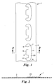
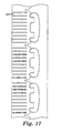
- Fig. 1 is a first preferred embodiment of the invention tab portion structure prior to formation in a precursor web 1.
- At least a semi-flexible tab carrier substrate web 2 is provided.
- the substrate web 2 can generally have a Gurley stiffness of 1-10 and is preferably formed of a nonwoven, woven or film, or laminate thereof.
- the overall tab carrier substrate should have a Gurley stiffness of from 1 to 500 and preferably 2 to 200, when used alone or in combination with other substrates or materials.
- the tab substrate 23 has a Gurley stiffness so as to provide that the tab member 3 of from 500 to 8000, preferably 1000 to 5000.
- the tab member has a Gurley stiffness at least two (2) times higher than that of the tab carrier substrate alone, or laminates including the substrate web 2, preferably at least five (5) times greater.
- the tab substrate is preferably formed out of a thermoplastic polymer which generally would have a thickness of from 0.1 mm to 1.0 mm, preferably 0.2 mm to 0.8 mm.
- the tab member also preferably has a tensile load at yield between 50 and 250 Newtons for a cross-sectional area of about 8 mm 2 and an elongation at yield of between 2% and 20%.
- the tab substrate 23 shown in Fig. 1 is generally in the form of the final tab member 3 and has an outer edge 4 and an inner edge 5 and ends 8, with a pivot point or region 7 that remains attached to the tab carrier substrate.
- the outer edge 4 is designed for insertion into a corresponding slot member 14 as disclosed in U.S. Patent No. 6,251,097 and the inner edge 5 includes one or more lip portions 6 which engage the outboard portion 15 of the slot member when tension is applied to the tab portion in a plane corresponding to the tab substrate web and/or the tab portion.
- Pivot point or region 7 is located between the outer edge 4 and the outermost edge of the lip portion 6 and is designed to allow the lip portions to move out of the plane with the tab carrier substrate 2 to create a V-shaped gap between the tab carrier substrate 12 and the lip portion 6.
- the lip portion extends at least 3mm preferable 3 to 10 mm from the pivot point or region 7, most preferably 4 to 8 mm.
- the portion of the tab member opposite the lip portion, along the pivot region also preferably will extend at least 2 mm, preferable 3 to 15 mm, from the pivot region, and generally would be at least 20 percent of the lip portion width, preferable at least 50 percent of the lip portion width. This is to provide rotational stability to the engaged tab member, so that when the lip portion is engaged it does not release by rotating around the engaged portion of the slot member when shear forces are applied.
- At least one layer of the tab carrier substrate 12 is continuous with a layer of the tab member, at least at the pivot region 7 of the tab member 3.
- one layer, forming a layer of both the tab carrier substrate and the tab member extends over at least 25 percent of the tab member, preferably at least 50 percent of the tab member and, in a preferred embodiment 100 percent of the tab member and the same layer also extends into at least 10 percent of the tab carrier substrate, preferably at least 25 percent and in a preferred embodiment at least 100 percent of the tab carrier substrate.
- the tab construction is also easy to manufacture by simple laminating techniques.
- the slot member 14 is similarly provided with a substrate web, which has flexibility similar to the tab carrier substrate 12 of the tab portion 11.
- the slot 18 includes a rigidifying element 13 around its periphery, which provides for easier insertion of the tab member and more secure engagement with the tab member 3 lip structure 6 and further defines the slot member outboard and inboard portions 15 and 16.
- the outboard portion 15 of the slot 18 engages at least one lip portion 6 when the slot member 14 and/or tab portion is placed under tension.
- the outer edge 4 of the tab member 3 is preferably curved or likewise tapered to allow for easier insertion into the slot 18.
- the lip portion(s) 6 are preferably curved or the like at their ends to ease the initiation of the gripping action with the outboard portion 15 of the slot 18.
- the tab substrates 23 forming the tab members can be joined to the substrate web(s) 2 and/or 9 by the use of adhesives, thermal or ultrasonic bonding, or by melt lamination of thermoplastic tab substrate material preferably onto porous substrate web(s).
- the substrate webs 2 and 9 as shown are separate webs but a single web could form both layers 2 and 9 where the web is folded adjacent the outer edge of the tab substrate 23.
- the tab substrate 23 is also preferably directly joined to the substrate web such that a substrate web will form an outer layer of the tab carrier substrate and the tab member creating a tab portion having a uniform outer surface, which in the case of a nonwoven substrate web would have the cloth-like feel of the nonwoven material.
- woven or film-like materials on laminates could be used as tab substrate webs.
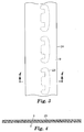
- the precursor material of Figs. 1 and 2 is then preferentially joined to a second tab substrate web 9 as shown in Figs. 3 and 4 where the two substrate webs are joined together by conventional lamination methods such as sonic bonding, adhesives, heat bonding, needle tacking or the like.
- the substrate web(s) and the tab substrate as shown are all mutually coplanar resulting a material having a relatively flat profile.
- the two webs 2 and 9 would preferably be joined together adjacent the inner edge 5 of the tab substrate 23 or tab member 3.
- the second substrate web 9 would likewise preferably be joined to an opposing outer face of the tab substrate 23 and could be formed of a like or similar material as substrate web 2.
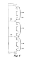
- the individual tab portions then could be cut from the precursor tab portion web 24 into the final form as shown in Fig. 6 by a suitably shaped knife blade or die or alternatively the tab could be partially cut from the finished precursor tab portion web 24, as will be described in more detail below.
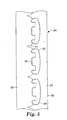
- Fig. 5 shows a laminate with a knife blade cut or die-cut suitable for partial trimming of the tab portions from a precursor tab portion web 24 so as to allow the formation of cut precursor tab portion web 24 where the tab portions are partially defined.
- the dotted or serrated lines 25 represent a perforated or serrated edge cut and the continuous lines 26 and 27 represent continuous knife blade or die edge cut.
- the curved continuous lines 26 represent continuous cutouts defining the lip portions of the tab member whereas the serrated line 25 represents a cutout for the outer edges of the tab member.
- the serrated cut portion 25 could be continuous. This would provide a continuous cut along an outer edge of the tab substrate web, which would allow removal of a waste edge trim 31 from the precursor tab portion web 24.
- this edge trim 31 can remain allowing the partially cut web to remain a continuous rectilinear web 30, which facilities even winding of the web into a roll form without formation of raggedy edges in the roll.
- the tapered continuous cut 27 can be of any suitable size or shape and merely defines the upper leading edge of the tab carrier substrate adjacent the tab member 3.
- Fig. 5 shows a tab substrate web 30, which has been cut by the knife blade or die.
- the portion 31 can either remain on the web leaving portion 32 or be subsequently removed such as shown in Fig. 6 where additional serrated cut lines 33 are shown which separates the individual tab portions 34. Shoulders 35 correspond to the knife blade cut 27.
- the tab substrate(s) 23 is sandwiched between two layers of the substrate webs 2 and 9.
- lines 33 are serrated, the individual tab portions are continuously separable from the web structure.
- the tab portions can subsequently be manually or automatically separated along the serrated edges 33 when needed.
- lines 33 could be continuous cuts made by the user of the tabs at the point of use.
- the cut around the tab members is outside the area containing the tab substrate at least at the outer edge of the tab substrate so that a tab substrate web edge extends out beyond the more rigid tab substrate by at least 0.5 mm. This softens the tab substrate edge making it more skin friendly.
- Fig. 17 shows a second embodiment of the invention similar to that shown in Figs. 1-8 where elastic strand structures 41 are provided on the substrate web 2 and/or 9 to provide for an elasticized or elasticizable structure.
- the elastic strands are printed onto either web 2 or 9 in accordance with U.S. Patent Application No. 10/012,698 and produced as show and described in Fig. 20 .
- the applied elastic strands can then be elasticized by suitable permanent deformation or elongation of the substrate webs 2 and/or 9 by any suitable elongation means such as interengaging rolls, external tension or the like.
- the substrate webs 2 and 9 could be made extensible by suitable methods as described below, or are provided as extensible when coated with the elastic strands.
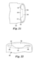
- Fig. 21 shows a third embodiment of the invention tab portion structure where a tab substrate 54 is in a form without predefined lip portions and the lip portions 56 are formed by a cutout edge 57.
- the remaining tab substrate 53 remains integral with the tab carrier substrate 59 where the inner edges of the lip portion cut-outs are preferably provided with a crease or indent 58 to allow the tab to bend or hinge out of the plane of the carrier substrate, for engagement of the lip portions 56 with a corresponding slot.
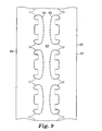
- Fig. 9 shows an alternative embodiment of a precursor web of the first embodiment tab portion where mirror image tab portions are provided on a single precursor tab portion web 60.
- mating precursor tab portions 63 and 67 are mirror image reflections of each other however they could also be offset or provided at other locations along the lengthwise direction of the completed precursor tab portion web.
- the center strip 61 can be subsequently removed along the perforated edges 64 and 65, where the continuous lines represent continuous cuts as per the description relative to Fig. 5 .
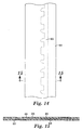
- Figs. 10 and 11 show a fifth embodiment of an invention precursor tab portion web where a continuous strip of a tab substrate 73 is laminated between substrate webs 72 and 79.
- the particular tab members can then be formed or defined in part by the knife blade or die (such as shown in embodiment of Fig. 5 ) cuts, as shown in Fig. 12 .
- Numeral 20 designates the continuous knife blade or die cuts of the tab carrier substrate 71 and the tab substrate 73 and 21 represents serrated cuts as per the Fig. 5 embodiment.
- the tab substrate could also be an extra layer of substrate web 72 or 79 that has been folded onto itself or the other substrate web or both, and laminated by adhesives ultrasonic or heat.
- a single substrate web 72 or 79 could be used and folded over onto itself and laminated to itself to form a tab substrate.
- tab substrate includes a separately applied strip of material or a laminate of an extra folded portion of a substrate web 72 or 79.
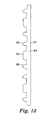
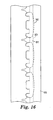
- Figs. 13-16 show a sixth embodiment of the invention where a continuous tab substrate 83 is joined to substrate webs where on one edge of the continuous tab substrate 83 the lip portions 86 are preformed.
- the tab substrate 83 has connecting portions 81 separating the yet to be formed tab member.
- Fig. 15 shows the tab substrate 83 joined between two substrate webs 82 and 88 by use of pressure-sensitive adhesives 89 and 84.
- the tab portions 90 would be partially formed by the use of a cut-out blade or die, as shown in embodiment of Fig. 5 for example, followed by separating the individual tab portions and discarding the connecting portions 81 and trim 85.
- Use of continuous tab substrates as per this embodiment are generally less advantageous than the use of discrete tab substrate materials.
- tab substrate material between the tab member is discarded, which is more costly in terms of material waste.
- Fig. 22 shows a seventh embodiment of the invention tab portion where a tab substrate 94 is joined to substrate webs 99, as shown in Fig. 21 , however, where only a single lip portion 96 is formed by die cutting or the like along line 92. Portion 95 of tab substrate 94 becomes detached as shown.
- the fastening device is fastened by passing the tab member 123 completely through the slot 18 of the slot member 14.
- the lip portion or portions 129 of the tab member 123 rotate into a plane generally parallel with the plane of the slot member 14 such that at least a part of a lip portion 129 overlaps at least a part of an outboard portion 15 of the slot member 14.
- the lip portion(s) 129 of the tab member 123 in combination with the remaining tab member carrier substrate 12 attached to the tab member 123 will prevent the tab member 123 from slipping back through the slot 18 and disengaging the fastening device.
- a portion of the tab member 123 will extend into the slot 18.
- the material forming the slot 13 will act to resist forces in shear, which tend to direct the tab member 123 and the slot member 14 apart.
- the tab member 123 is preferably an elongated member having wing elements 132 that remain integral with the carrier substrate 12 attached to the tab member 123.
- the wing elements 132 prevent slippage of the tab member in the slot while increasing the gripping action of the tab member lip portion(s) 129.
- the wing element 132 must be able to twist or bend along the pivot region 127 so as to allow the lip portion 129 to rotate away from the plane of the tab carrier substrate.
- the wing elements 132 can be made to bend by mechanical folding if needed to help the lip portions pivot away from the carrier substrate. Alternatively, a crease can be formed by scoring or other known methods, creating a weakened zone by decreasing the wing element thickness along pivot line or region 127.
- the wing elements 132 are generally provided along one or both outermost side edges of the tab member 123 outside of the tab member 123 region having the lip portion(s) 129 and are at least partially coextensive with the lip portion(s) 129 in the lengthwise direction L of the tab portion (i.e., in the region of the attached carrier substrate 12).
- the wing elements 132 also remain integral with the carrier substrate 12 in the main body of the tab portion.
- layers forming the tab carrier substrate 12 also generally form one or both outer faces of the tab member 123.
- the lip portion 129 lifts away from the tab member carrier substrate 12 forming a V-shaped catching surface between the lip portion 129 and the substrate 12 and wing elements 132.
- the bottom leg of the V is formed by the flexible tab carrier substrate 12 and wing elements 132.
- the upper portion of the leg of the V is formed at least by the more rigid tab member 123. Since the lip portion 129 of the tab member 123 is cut from the carrier substrate along lines 131, the lip portion 129 and the remaining cutout portion of the tab carrier substrate 12 are reverse mirror images of the other, the bottom leg of the V formed by the remaining carrier substrate is joined to the lip portion of the tab member at their respective terminal edges or ends and along pivot regions 127.
- the tab substrate material can be provided with elastic or inelastic reinforcing elements 141 printed on the carrier substrate as per the Fig. 17 embodiment. These elements prevent distortion of the tab substrate material when force is applied to the tab portion in the lengthwise direction L.
- These reinforcing elements preferably extend into the region of the tab portion containing the wing elements 32 in the lengthwise direction L so that forces applied to the tab portion in the lengthwise direction L are transferred from the reinforcing elements 141 to the wing portions, with no unreinforced carrier substrate 12 between the terminal end of the wing portion 132 and the terminal ends of the reinforcement elements in the lengthwise direction L.
- the reinforcing elements and the wing portions will overlap by at least 1 mm or more, preferably 2 mm or more.
- Additional reinforcing elements 130 could also be provided in the tab region between the wing portions 132 to provide further reinforcement of weak carrier substrate 12 material, if needed.
- This additional reinforcement element 30 preferably could also overlap with elements 141, or be an extension of the elements 141 and could extend up to, or be integral with, the tab member 123.
- the substrates which can be used in connection with the present invention may have a variety of constructions.
- the substrates may be a woven material, nonwoven material, knit material, paper, film, or any other continuous media.
- the substrates may have a wide variety of properties, such as extensibility, elasticity, flexibility, conformability, breathability, porosity, stiffness, etc.
- the substrates may include pleats, corrugations or other deformations from a flat planar sheet configuration.
- Suitable processes for making a nonwoven web include, but are not limited to, airlaying, spunbond, spunlace, bonded melt blown webs and bonded carded web formation processes.
- Spunbond nonwoven webs are made by extruding a molten thermoplastic, as filaments from a series of fine die orifices in a spinneret. The diameter of the extruded filaments is rapidly reduced under tension by, for example, by non-eductive or eductive fluid-drawing or other known spunbond mechanisms, such as described in U.S. Patent Nos.
- the spunbond web is preferably bonded (point or continuous bonding).
- the nonwoven web layer may also be made from bonded carded webs.
- Carded webs are made from separated staple fibers, which fibers are sent through a combing or carding unit which separates and aligns the staple fibers in the machine direction so as to form a generally machine direction-oriented fibrous nonwoven web.
- randomizers can be used to reduce this machine direction orientation.
- the carded web is then bonded by one or more of several bonding methods to give it suitable tensile properties.
- One bonding method is powder bonding wherein a powdered adhesive is distributed through the web and then activated, usually by heating the web and adhesive with hot air.
- Another bonding method is pattern bonding wherein heated calender rolls or ultrasonic bonding equipment are used to bond the fibers together, usually in a localized bond pattern though the web can be bonded across its entire surface if so desired.
- the more the fibers of a web are bonded together the greater the nonwoven web tensile properties.
- Airlaying is another process by which fibrous nonwoven webs useful in the present invention can be made.
- bundles of small fibers usually having lengths ranging between about 6 to about 19 millimeters are separated and entrained in an air supply and then deposited onto a forming screen, often with the assistance of a vacuum supply.
- the randomly deposited fibers are then bonded to one another using, for example, hot air or a spray adhesive.
- Meltblown nonwoven webs may be formed by extrusion of thermoplastic polymers from multiple die orifices, which polymer melt streams are immediately attenuated by hot high velocity air or steam along two faces of the die immediately at the location where the polymer exits from the die orifices.
- the resulting fibers are entangled into a coherent web in the resulting turbulent airstream prior to collection on a collecting surface.
- meltblown webs must be further bonded such as by through air bonding, heat or ultrasonic bonding as described above.
- a web can be made extensible by skip slitting as is disclosed in, e.g., International Publication No. WO 96/10481 . If an elastic, extensible web is desired, the slits are discontinuous and are generally cut on the web prior to the web being attached to any elastic component. Although more difficult, it is also possible to create slits in the nonelastic web layer after the nonelastic web is laminated to the elastic web. At least a portion of the slits in the nonelastic web should be generally perpendicular (or have a substantial perpendicular vector) to the intended direction of extensibility or elasticity (the at least first direction) of the elastic web layer.
- perpendicular it is meant that the angle between the longitudinal axis of the chosen slit or slits and the direction of extensibility is between 60 and 120 degrees.
- a sufficient number of the described slits are generally perpendicular such that the overall laminate is elastic. The provision of slits in two directions is advantageous when the elastic laminate is intended to be elastic in at least two different directions.
- a nonwoven web used in connection with the present invention can also be a necked or reversibly necked nonwoven web as described in U.S. Patent Nos. 4,965,122 ; 4,981,747 ; 5,114,781 ; 5,116,662 ; and 5,226,992 .
- the nonwoven web is elongated in a direction perpendicular to the desired direction of extensibility. When the nonwoven web is set in this elongated condition, it will have stretch and recovery properties in the direction of extensibility.
- the substrates may preferably exhibit some porosity on one or both of the major surfaces of the substrate such that when the tab substrate is formed by printing a molten thermoplastic composition as shown in Fig. 20 , a mechanical bond is formed between the molten thermoplastic composition and the substrate as the molten thermoplastic composition infiltrates and/or encapsulates a portion of the porous surface of the substrate.
- the term "porous" includes both structures that include voids formed therein, as well as structures formed of a collection of fibers (e.g., woven, nonwoven, knit, etc.) that allow for the infiltration of molten thermoplastic composition into the interstices between fibers. If the porous surface includes fibers, the thermoplastic composition may preferably encapsulate fibers or portions of fibers on the surface of the substrate.
- the type and construction of the material or materials in the substrate should be considered when selecting an appropriate substrate to which a molten thermoplastic composition is applied.
- such materials are of the type and construction that do not melt, soften, or otherwise disintegrate under the temperatures and pressures experienced during the step of transferring the thermoplastic composition to the substrate.
- the substrate should have sufficient internal strength such that it does not fall apart during the process.
- the substrate has sufficient strength in the machine direction at the temperature of the transfer roll to remove it intact from the transfer roll.
- substrates depicted in the various cross-sectional views of the articles manufactured according to the methods of the present invention are illustrated as single layer structures, it should be understood that the substrates might be of single or multi-layer construction. If a multi-layer construction is used, it will be understood that the various layers may have the same or different properties, constructions, etc.
- thermoplastic and variations thereof means a polymer or polymeric composition that softens when exposed to heat and returns to its original condition or near its original condition when cooled to room temperature.
- Preferred thermoplastic compositions are those that are melt processable. Such polymers are those that will flow, yet not significantly degrade during a melt process.
- nonelastomeric thermoplastic compositions that may be used in connection with the present invention include, but are not limited to, polyurethanes, polyolefins (e.g., polypropylenes, polyethylenes, etc.), polystyrenes, polycarbonates, polyesters, polymethacrylates, ethylene vinyl acetate copolymers, ethylene vinyl alcohol copolymers, polyvinylchlorides, acrylate modified ethylene vinyl acetate polymers, ethylene acrylic acid copolymers, nylons, fluorocarbons, or blends or copolymers thereof, etc.
- polyurethanes e.g., polypropylenes, polyethylenes, etc.
- polystyrenes e.g., polypropylenes, polyethylenes, etc.
- polystyrenes e.g., polystyrenes
- polycarbonates e.g., polypropylenes, polyethylenes, etc.
- polyesters e.g., polyprop
- a nonelastomeric thermoplastic polymer is one that melts and returns to its original condition or near its original condition upon cooling and which does not exhibit elastomeric properties at ambient conditions (e.g., room temperature and pressure).
- "nonelastomeric" means that the material will not substantially resume its original shape after being stretched.
- the nonelastomeric materials may preferably sustain permanent set following deformation and relaxation, which set is preferably at least about 20 percent or more, and more preferably at least about 30 percent or more of the original length at moderate elongation, e.g., about 50% (for those materials that can even be stretched up to 50% without fracture or other failure).
- the nonelastomeric thermoplastic compositions used in connection with the present invention can also be combined with various additives for desired effect. These include, for example, fillers, viscosity reducing agents, plasticizers, tackifiers, colorants (e.g., dyes or pigments), antioxidants, antistatic agents, bonding aids, antiblocking agents, slip agents, stabilizers (e.g., thermal and ultraviolet), foaming agents, microspheres, glass bubbles, reinforcing fibers (e.g., microfibers), internal release agents, thermally conductive particles, electrically conductive particles, and the like.
- additives for desired effect. These include, for example, fillers, viscosity reducing agents, plasticizers, tackifiers, colorants (e.g., dyes or pigments), antioxidants, antistatic agents, bonding aids, antiblocking agents, slip agents, stabilizers (e.g., thermal and ultraviolet), foaming agents, microspheres, glass bubbles, reinforcing fibers (e.g
- a transfer tool 101 or 102 that can be used to deposit the tab substrate.
- the transfer tools 101 and/or 102 generally include a depression formed therein.
- the depressions can be of the form of the tab substrate or other elements or multiple depressions can form the tab substrate or the like.
- the depressions can be of the same size or of differing sizes dispersed over the surface of the transfer rolls 101 or 102, both in terms of footprint as well as depression volume.
- the depressions used to form the tab substrate is preferably a composite of cells or smaller depressions formed in the surface by any suitable technique, e.g., machining, etching, laser ablation, etc.
- the depressions on transfer rolls 101 or 102 used in connection with the present invention may be characterized in terms of the area occupied by their footprint on the exterior surface of the forming tool, a maximum dimension of the footprint (in any direction on the surface of the roll), the volume of the depression, the shape of the footprint, etc.
- each of the depressions When characterized in terms of the area occupied by the footprint of the depressions, each of the depressions may have a footprint with an area of about 4 square millimeters (mm 2 ) or more. In other situations, each of the depressions may have footprints with an area of about 8 mm 2 or more.
- the depressions may be characterized is in terms of the largest footprint dimension as measured on the surface of the transfer roll.
- the largest footprint dimension of the footprint it may be that the depressions have a largest footprint dimension of about 2 mm or more, in some instances about 5 mm or more.
- the depressions used in connection with the present invention may be characterized is in terms of depression volume.
- the depressions may have a depression volume of at least about three (3) cubic millimeters (mm 3 ) or more, or alternatively a depression volume of about five (5) cubic millimeters or more.
- Volume may be important because at least some of the molten thermoplastic composition may be retained within the depression during the transfer process, i.e., the depression volume may preferably be oversized relative to the preferred volume of the discrete polymeric regions to be formed by the depressions to compensate for retention of thermoplastic composition within the depressions.
- the orientation of the depression on a transfer roll may be selected based on a variety of factors.
- the elongated depression may be aligned in the machine direction (i.e., the direction of travel of a substrate), in the cross-web direction (i.e., transverse to the direction of travel of the substrate), or any other orientation between machine direction and cross-web direction.
- Attachment of two substrates 105, 106 as shown in Fig. 20 may be accomplished using the deposited polymeric regions of the tab substrate alone when the lamination is performed, while the polymer regions are still in a somewhat molten state such that they can bond with counterpart polymeric regions on the opposing substrate or to the opposing substrate itself.
- One advantage of this construction is that the lamination may be accomplished without the need for additional materials and/or process steps.
- the lamination between substrates may alternatively be assisted by a variety of materials and/or techniques known to those skilled in the art, e.g., thermal bonding, adhesives, resins, tie films/webs, etc. See, e.g., U.S. Patent Nos. 2,787,244 ; 3,694,867 ; 4,906,492 ; 5,685,758 ; and 6,093,665 .
- the process of providing tab substrates includes delivering a supply of a molten thermoplastic composition to the exterior surface of one or both of transfer rolls 101 or 102 which include a one or more depressions formed in its exterior surface forming the tab substrate.
- the molten thermoplastic composition is supplied to the exterior surface of the transfer roll by a delivery apparatus in the form of a trough 111 and/or 112 (or other supply apparatus, e.g., extruder, gear pump, etc.).
- thermoplastic composition is wiped or removed from the exterior surface by a doctor blade acting against the exterior surface of the transfer roll. Although it may be ideal to remove all of the thermoplastic composition from the exterior surface of the transfer roll, some of the thermoplastic composition may remain on the exterior surface after wiping by the doctor blade.
- the depressions formed in the exterior surface of the transfer rolls 101 or 102 preferably receive a portion of the molten thermoplastic composition when the molten thermoplastic composition is deposited on the exterior surface of the transfer roll. If the depressions are not completely filled during or by the deposition of molten thermoplastic composition, the wiping action of the doctor blade on the exterior surface of the transfer roll may assist in substantially filling the depressions with molten thermoplastic composition.
- the transfer roll continues to rotate until the depressions and the molten thermoplastic composition they contain are forced into contact with the substrate against backup roll 103 or 104 at the transfer nip 113 or 114 (i.e., the nip formed by the transfer roll and the backup roll). It is at this point that transfer of the molten thermoplastic composition in the depressions to the substrate begins. It should be understood that under certain conditions, only a portion of the thermoplastic composition in the depressions might transfer to the substrate.
- porous includes both structures that include voids formed therein, as well as structures formed of a collection of fibers (e.g., woven, nonwoven or knit) that allow for the penetration of molten thermoplastic compositions.
- the nip pressure between the transfer roll and the backup roll is preferably sufficient such that a portion of the thermoplastic composition infiltrates and/or encapsulates a portion of the porous substrate to improve attachment of the tab substrate polymer to the substrate(s).
- the surface of the substrate includes fibers (e.g., where the substrate includes woven, nonwoven, or knit materials on its major surfaces)
- the thermoplastic composition encapsulate all or a portion of at least some of the fibers on the surface of the substrate to improve attachment of the discrete polymeric regions to the substrate.
- the molten thermoplastic composition in the depressions may completely permeate the substrate if, e.g., the substrate is porous throughout its thickness. In other instances, penetration of the molten thermoplastic composition may be limited to the outer layer or layers of the substrate.
- the outer surfaces of the substrate may exhibit some porosity, that porosity may not necessarily extend through the entire thickness of the substrate.
- the substrate may have a variety of different layers, with one of the layers being substantially non-porous.
- the overall thickness of the substrate may render it non-porous as a whole, even though the outer surfaces of the substrate exhibit some porosity as discussed above.
- the backup roll 103 or 104 may possess a variety of different characteristics depending on the types of substrate materials and/or molten thermoplastic compositions being processed.
- the exterior of the backup roll may be a rubber or other conformable material that conforms to the shape of the transfer roll. If a conformable material such as rubber is used, it may, e.g., have a durometer of, e.g., about 10-90 Shore A.
- the substrate 106 and/or 105 then continues around the backup roll.
- a portion of the molten thermoplastic composition in the depressions may remain in the depressions while the substrate is pulled away from the transfer roll.
- the molten thermoplastic composition in the depressions may tend to elongate or string between the depressions in transfer roll and the substrate.
- a device such as a hot wire may be used to sever any strands of thermoplastic composition that may be formed as the substrate separates from the transfer roll.
- Other devices and/or techniques may be used to accomplish the desired severing of any molten thermoplastic composition strands. Examples may include, but are not limited to hot air knives, lasers, etc.
- stringing of the thermoplastic composition may not be encountered during manufacturing.
- the formed precursor web 107 is then fed to a die cut station 108 to form a partially cut precursor web 109 which can then be wound into a roll.
- a nonextensible substrate can be made extensible by, e.g., providing slits in the substrate.
- the slits are preferably spanned by at least one of the discrete elastomeric polymeric regions.
- Some exemplary slitting processes to provide or improve extensibility of a substrate are described in International Publication No. WO 96/10481 .
- Other techniques may also be used to provide or improve the extensibility of substrates used in connection with the present invention.
- the mechanical stretching processes described in U.S. Patent Nos. 4,223,059 and 5,167,897 may be used to provide or improve extensibility.
- the system may also laminate substrates together, each using both the elastomeric and nonelastomeric printed discrete polymeric regions for the Fig. 17 embodiment or the like as described above.
- the Fig. 20 system could be used for the purpose where one transfer station deposits nonelastomeric discrete tab substrates onto a substrate 106 and the second transfer station produces elastomeric discrete polymeric regions on second substrate 105. Both substrates 105 and 106 are then directed into a laminating station 100 that produces a laminated composite web 107 which, in the depicted embodiment, would provide both the nonelastomeric tab element and the elastomeric discrete polymeric regions located within the surrounding layers of substrates as shown in Fig. 17 .
- elastomeric thermoplastic compositions used for elastic discrete polymeric regions should be capable of flowing or entering into depressions formed in a polymer transfer roll as will be described below.
- Suitable elastomeric thermoplastic compositions are those that are melt processable. Such polymers are those that will flow sufficiently to at least partially fill the depressions, yet not significantly degrade during a melt process.
- a wide variety of elastomeric thermoplastic compositions have suitable melt and flow characteristics for use in the process of the present invention depending on the geometry of the depressions and the processing conditions. It may further be preferred that the melt processable materials and conditions of processing are selected such that any viscoelastic recovery properties of the thermoplastic composition do not cause it to significantly withdraw from the wall(s) of the depressions until transfer of the thermoplastic composition to a substrate is desired.
- elastomeric means that the material will substantially resume its original shape after being stretched. Further, the elastomeric materials may preferably sustain only small permanent set following deformation and relaxation, which set is preferably no greater than about 30 percent and more preferably no greater than about 20 percent of the original length at moderate elongation, e.g., about 50%.
- the elastomeric materials can be both pure elastomers and blends with an elastomeric phase or content that will still exhibit substantial elastomeric properties at room temperature.
- U.S. Patent No. 5,501,679 provides some further discussion regarding elastomeric materials that may be considered for use in connection with the present invention.
- the elastomeric thermoplastic compositions can include one or more polymers.
- the elastomeric thermoplastic composition could be a blend with an elastomeric phase such that the composition exhibits elastomeric properties at room temperature.
- Suitable elastic thermoplastic polymers include block copolymers such as conventional A-B or A-B-A block copolymers (e.g., styrene-isoprene-styrene, styrenebutadiene-styrene, styrene-ethylene-butylene-styrene block copolymers), elastomeric polyurethanes, olefinic elastomers, particularly elastomeric ethylene copolymers (e.g., ethylene vinyl acetates, ethylene/octene copolymer elastomers, ethylene/propylene/diene terpolymer elastomers), as well as mixtures of these with each other, with other
- the elastomeric thermoplastic compositions used in connection with the present invention can also be combined with various additives for desired effect. These include, for example, fillers, viscosity reducing agents, plasticizers, tackifiers, colorants (e.g., dyes or pigments), antioxidants, antistatic agents, bonding aids, antiblocking agents, slip agents, stabilizers (e.g., thermal and ultraviolet), foaming agents, microspheres, glass bubbles, reinforcing fibers (e.g., microfibers), internal release agents, thermally conductive particles, electrically conductive particles, and the like.
- additives for desired effect. These include, for example, fillers, viscosity reducing agents, plasticizers, tackifiers, colorants (e.g., dyes or pigments), antioxidants, antistatic agents, bonding aids, antiblocking agents, slip agents, stabilizers (e.g., thermal and ultraviolet), foaming agents, microspheres, glass bubbles, reinforcing fibers (e.
- thermoplastic polymer in addition to the deposition of nonelastic or elastic thermoplastic polymer in discrete regions, it is also contemplated that additional materials can be coated onto a major surface of the substrate using known methods. Such materials could be, for example adhesives, as described in, e.g., U.S. Patent Nos. 5,019,071 ; 5,028,646 ; and 5,300,057 ; or cohesives as described in, e.g. U.S. Patent Nos. 5,389,438 and 6,261,278 .
Claims (26)
- Stratifié à languette de fixation (10) pour une utilisation dans un système de fermeture à fente et languette, comprenant une partie constituée d'une languette (11) comportant un élément de languette rigide (3) et un substrat support de languette flexible correspondant (12) dans lequel l'élément de languette rigide (3) comporte un bord externe (4) et un bord interne (5), le bord interne (5) formant au moins une partie constituée d'une lèvre (6), l'élément de languette (3) formé d'un substrat de languette rigide (23) étant appliqué par stratification sur au moins une bande de substrat flexible (2, 9),a) laquelle bande de substrat (2, 9) forme aussi au moins en partie le substrat support de languette (12),b) laquelle bande de substrat flexible (2, 9) est dans un seul plan à l'endroit où elle est continue entre le substrat support de languette (12) et l'élément de languette rigide (3) de sorte que le substrat support de languette (12) et l'élément de languette rigide (3) soient coplanaires ; etc) dans lequel la partie constituée d'une lèvre (6) est détachée du substrat support de languette (12) de façon à pouvoir pivoter en s'éloignant du substrat support de languette coplanaire (12).
- Stratifié à languette de fixation (10) selon la revendication 1, dans lequel ladite au moins une bande de substrat flexible (2, 9) est une bande poreuse.
- Stratifié à languette de fixation (10) selon la revendication 2, dans lequel ladite au moins une bande de substrat flexible (2, 9) est une bande fibreuse non tissée.
- Stratifié à languette de fixation (10) selon la revendication 2, dans lequel le substrat de languette rigide est un matériau polymère thermoplastique.
- Stratifié à languette de fixation (10) selon la revendication 4, dans lequel le matériau thermoplastique du substrat de languette rigide pénètre au moins en partie dans la structure poreuse de la bande de substrat flexible (2, 9).
- Stratifié à languette de fixation (10) selon la revendication 5, dans lequel ladite au moins une bande de substrat flexible (2, 9) est fixée aux éléments de languette pour s'étendre sur au moins 25 % de l'élément de languette (3).
- Stratifié à languette de fixation (10) selon la revendication 6, dans lequel la bande de substrat flexible (2, 9) s'étend sur au moins 50 % de l'élément de languette (3).
- Stratifié à languette de fixation (10) selon la revendication 6, dans lequel la bande de substrat flexible (2, 9) s'étend sur au moins 10 % du substrat support de languette (12).
- Stratifié à languette de fixation (10) selon la revendication 8, dans lequel la bande de substrat flexible (2, 9) s'étend sur au moins 25 % du substrat support de languette (12).
- Stratifié à languette de fixation (10) selon la revendication 1, dans lequel le substrat de languette rigide est appliqué par stratification sur deux bandes de substrat flexibles (2, 9) sur des faces opposées du substrat de languette rigide.
- Stratifié à languette de fixation (10) selon la revendication 10, dans lequel les deux bandes de substrat flexibles (2, 9) forment aussi au moins en partie le substrat support de languette (12).
- Stratifié à languette de fixation (10) selon la revendication 11, dans lequel au moins un élément élastique est fixé à une bande de substrat flexible (2, 9) formant le substrat support de languette (12), de façon à produire un stratifié à languette de fixation élastique.
- Stratifié à languette de fixation (10) selon la revendication 1, dans lequel l'élément de languette rigide (3) a un bord externe courbe.
- Stratifié à languette de fixation (10) selon la revendication 13, dans lequel l'élément de languette rigide (3) a un bord interne courbe formant la partie constituée d'une lèvre (6), laquelle partie constituée d'une lèvre (6) s'étend sur au moins 3 à 10 mm à partir d'un point ou d'une région de pivotement.
- Stratifié à languette de fixation (10) selon la revendication 1, dans lequel l'élément de languette rigide (3) a une rigidité Gurley de 500 à 8 000.
- Stratifié à languette de fixation (10) selon la revendication 15, dans lequel le substrat support de languette (12) a une rigidité Gurley de 1 à 500.
- Stratifié à languette de fixation (10) selon la revendication 16, dans lequel l'élément de languette rigide (3) a une rigidité Gurley au moins deux fois supérieure à celle du substrat support de languette (12).
- Stratifié à languette de fixation (10) selon la revendication 17, dans lequel la rigidité de l'élément de languette rigide (3) est au moins cinq fois supérieure à celle du substrat support de languette (12).
- Stratifié à languette de fixation (10) selon la revendication 17, dans lequel le substrat de languette (12) est un polymère thermoplastique ayant une épaisseur de 0,1 à 1,0 mm.
- Stratifié à languette de fixation (10) selon la revendication 19, dans lequel le substrat de languette (12) est un polymère thermoplastique ayant une épaisseur de 0,2 à 0,8 mm.
- Stratifié à languette de fixation (10) selon la revendication 1, dans lequel la partie constituée d'une lèvre (6) pivote en s'éloignant du substrat support de languette (12) en formant un espace en forme de V, laquelle partie constituée d'une lèvre (6) s'étend sur au moins 3 mm à partir d'un point ou d'une région de pivotement.
- Stratifié à languette de fixation (10) selon la revendication 1, dans lequel la partie constituée d'une lèvre (6) pivote en s'éloignant du substrat support de languette (12) en formant un espace en forme de V, laquelle partie constituée d'une lèvre (6) s'étend sur au moins 3 à 10 mm à partir d'un point ou d'une région de pivotement.
- Stratifié à languette de fixation (10) selon la revendication 21, dans lequel la partie constituée d'une lèvre (6) est une image miroir inverse d'une partie échancrée du substrat support de languette (12).
- Stratifié à languette de fixation (10) selon la revendication 1, dans lequel l'élément de languette comprend en outre au moins un élément formant une aile qui s'étend dans la portion de l'élément de languette comprenant la partie constituée d'une lèvre (6) dans la direction de la longueur de la partie constituée d'une languette, lesquels éléments formant une aile ne peuvent pas pivoter en s'éloignant du substrat support (12).
- Stratifié à languette de fixation (10) selon la revendication 24, dans lequel ledit au moins un élément formant une aile est fixé au substrat support de languette (12).
- Stratifié à languette de fixation (10) selon la revendication 25, dans lequel il y a deux éléments formant une aile sur les bords situés le plus à l'extérieur de l'élément de languette en dehors de toutes les parties constituées d'une lèvre (6).
Applications Claiming Priority (5)
| Application Number | Priority Date | Filing Date | Title |
|---|---|---|---|
| US170619 | 1993-12-20 | ||
| US350204 | 1994-12-02 | ||
| US17061902A | 2002-06-13 | 2002-06-13 | |
| US10/350,204 US6880211B2 (en) | 2002-06-13 | 2003-01-23 | Macro closure device for disposable articles |
| PCT/US2003/011708 WO2003105739A1 (fr) | 2002-06-13 | 2003-04-15 | Dispositif de macrofermeture pour articles jetables |
Publications (2)
| Publication Number | Publication Date |
|---|---|
| EP1511454A1 EP1511454A1 (fr) | 2005-03-09 |
| EP1511454B1 true EP1511454B1 (fr) | 2010-12-15 |
Family
ID=29738973
Family Applications (1)
| Application Number | Title | Priority Date | Filing Date |
|---|---|---|---|
| EP03728417A Expired - Lifetime EP1511454B1 (fr) | 2002-06-13 | 2003-04-15 | Dispositif de macrofermeture pour articles jetables |
Country Status (8)
| Country | Link |
|---|---|
| EP (1) | EP1511454B1 (fr) |
| JP (1) | JP2005529683A (fr) |
| CN (1) | CN1289046C (fr) |
| AU (1) | AU2003234111A1 (fr) |
| BR (1) | BR0311429A (fr) |
| MX (1) | MXPA04012352A (fr) |
| RU (1) | RU2318483C2 (fr) |
| WO (1) | WO2003105739A1 (fr) |
Families Citing this family (2)
| Publication number | Priority date | Publication date | Assignee | Title |
|---|---|---|---|---|
| JP4949618B2 (ja) * | 2004-03-31 | 2012-06-13 | ユニ・チャーム株式会社 | 着用物品 |
| EP2077813A2 (fr) * | 2006-11-03 | 2009-07-15 | The Procter and Gamble Company | Article avec un système de fixation secondaire |
Family Cites Families (4)
| Publication number | Priority date | Publication date | Assignee | Title |
|---|---|---|---|---|
| US4718900A (en) * | 1985-09-06 | 1988-01-12 | Kimberly-Clark Corporation | Form-fitting self-adjusting disposable garment with straight waist appearance |
| SE507111C2 (sv) * | 1995-07-07 | 1998-03-30 | Moelnlycke Ab | Fastsättningsorgan för att med varandra förbinda motstående främre och bakre sidopartier hos ett absorberande alster |
| CA2510940A1 (fr) * | 1997-09-04 | 1999-03-11 | The Procter & Gamble Company | Dispositif de fixation pour articles absorbants |
| US6251097B1 (en) * | 1997-09-04 | 2001-06-26 | The Procter & Gamble Company | Absorbent article fastening device |
-
2003
- 2003-04-15 EP EP03728417A patent/EP1511454B1/fr not_active Expired - Lifetime
- 2003-04-15 WO PCT/US2003/011708 patent/WO2003105739A1/fr active Application Filing
- 2003-04-15 AU AU2003234111A patent/AU2003234111A1/en not_active Abandoned
- 2003-04-15 MX MXPA04012352A patent/MXPA04012352A/es active IP Right Grant
- 2003-04-15 JP JP2004512649A patent/JP2005529683A/ja active Pending
- 2003-04-15 BR BR0311429-5A patent/BR0311429A/pt active Search and Examination
- 2003-04-15 RU RU2004133763/14A patent/RU2318483C2/ru not_active IP Right Cessation
- 2003-04-15 CN CNB03813764XA patent/CN1289046C/zh not_active Expired - Fee Related
Also Published As
| Publication number | Publication date |
|---|---|
| AU2003234111A1 (en) | 2003-12-31 |
| EP1511454A1 (fr) | 2005-03-09 |
| BR0311429A (pt) | 2005-03-22 |
| WO2003105739A1 (fr) | 2003-12-24 |
| CN1658813A (zh) | 2005-08-24 |
| RU2318483C2 (ru) | 2008-03-10 |
| CN1289046C (zh) | 2006-12-13 |
| MXPA04012352A (es) | 2005-04-08 |
| JP2005529683A (ja) | 2005-10-06 |
| RU2004133763A (ru) | 2005-07-10 |
Similar Documents
| Publication | Publication Date | Title |
|---|---|---|
| US6880211B2 (en) | Macro closure device for disposable articles | |
| EP1451013B1 (fr) | Bandes composites presentant des zones polymeres elastiques | |
| EP1444093B1 (fr) | toiles composites comprenant des ilots de polymeres de renfort et des ilots de polymeres elastiques | |
| TWI571250B (zh) | 繫固帶及其製造方法 | |
| JP4275859B2 (ja) | 弾性タブ積層品 | |
| US7947358B2 (en) | Method and an arrangement for producing basic fastener tab material, such basic starting material, and fastener tabs | |
| US6715188B1 (en) | Hinged tab for slot and tab closure systems | |
| JP5996123B2 (ja) | 積層体を含む吸収性物品及びその作製方法 | |
| US7875012B2 (en) | Elastic disposal means | |
| US20090142577A1 (en) | Composite webs and methods of manufacturing the same | |
| WO2019207544A1 (fr) | Feuille stratifiée élastique, élément de languette et matériau hygiénique | |
| EP1511454B1 (fr) | Dispositif de macrofermeture pour articles jetables | |
| JP2022550766A (ja) | 廃棄用タブ、廃棄用タブを製造する方法、廃棄用テープ、及び廃棄用タブを有する吸収性物品 |
Legal Events
| Date | Code | Title | Description |
|---|---|---|---|
| PUAI | Public reference made under article 153(3) epc to a published international application that has entered the european phase |
Free format text: ORIGINAL CODE: 0009012 |
|
| 17P | Request for examination filed |
Effective date: 20041208 |
|
| AK | Designated contracting states |
Kind code of ref document: A1 Designated state(s): AT BE BG CH CY CZ DE DK EE ES FI FR GB GR HU IE IT LI LU MC NL PT RO SE SI SK TR |
|
| AX | Request for extension of the european patent |
Extension state: AL LT LV MK |
|
| DAX | Request for extension of the european patent (deleted) | ||
| 17Q | First examination report despatched |
Effective date: 20070209 |
|
| GRAP | Despatch of communication of intention to grant a patent |
Free format text: ORIGINAL CODE: EPIDOSNIGR1 |
|
| GRAS | Grant fee paid |
Free format text: ORIGINAL CODE: EPIDOSNIGR3 |
|
| GRAA | (expected) grant |
Free format text: ORIGINAL CODE: 0009210 |
|
| AK | Designated contracting states |
Kind code of ref document: B1 Designated state(s): AT BE BG CH CY CZ DE DK EE ES FI FR GB GR HU IE IT LI LU MC NL PT RO SE SI SK TR |
|
| REG | Reference to a national code |
Ref country code: GB Ref legal event code: FG4D Ref country code: CH Ref legal event code: EP |
|
| REG | Reference to a national code |
Ref country code: IE Ref legal event code: FG4D |
|
| REF | Corresponds to: |
Ref document number: 60335366 Country of ref document: DE Date of ref document: 20110127 Kind code of ref document: P |
|
| REG | Reference to a national code |
Ref country code: NL Ref legal event code: VDEP Effective date: 20101215 |
|
| PG25 | Lapsed in a contracting state [announced via postgrant information from national office to epo] |
Ref country code: SI Free format text: LAPSE BECAUSE OF FAILURE TO SUBMIT A TRANSLATION OF THE DESCRIPTION OR TO PAY THE FEE WITHIN THE PRESCRIBED TIME-LIMIT Effective date: 20101215 Ref country code: AT Free format text: LAPSE BECAUSE OF FAILURE TO SUBMIT A TRANSLATION OF THE DESCRIPTION OR TO PAY THE FEE WITHIN THE PRESCRIBED TIME-LIMIT Effective date: 20101215 Ref country code: SE Free format text: LAPSE BECAUSE OF FAILURE TO SUBMIT A TRANSLATION OF THE DESCRIPTION OR TO PAY THE FEE WITHIN THE PRESCRIBED TIME-LIMIT Effective date: 20101215 Ref country code: FI Free format text: LAPSE BECAUSE OF FAILURE TO SUBMIT A TRANSLATION OF THE DESCRIPTION OR TO PAY THE FEE WITHIN THE PRESCRIBED TIME-LIMIT Effective date: 20101215 Ref country code: CY Free format text: LAPSE BECAUSE OF FAILURE TO SUBMIT A TRANSLATION OF THE DESCRIPTION OR TO PAY THE FEE WITHIN THE PRESCRIBED TIME-LIMIT Effective date: 20101215 Ref country code: NL Free format text: LAPSE BECAUSE OF FAILURE TO SUBMIT A TRANSLATION OF THE DESCRIPTION OR TO PAY THE FEE WITHIN THE PRESCRIBED TIME-LIMIT Effective date: 20101215 Ref country code: BG Free format text: LAPSE BECAUSE OF FAILURE TO SUBMIT A TRANSLATION OF THE DESCRIPTION OR TO PAY THE FEE WITHIN THE PRESCRIBED TIME-LIMIT Effective date: 20110315 |
|
| PG25 | Lapsed in a contracting state [announced via postgrant information from national office to epo] |
Ref country code: PT Free format text: LAPSE BECAUSE OF FAILURE TO SUBMIT A TRANSLATION OF THE DESCRIPTION OR TO PAY THE FEE WITHIN THE PRESCRIBED TIME-LIMIT Effective date: 20110415 Ref country code: EE Free format text: LAPSE BECAUSE OF FAILURE TO SUBMIT A TRANSLATION OF THE DESCRIPTION OR TO PAY THE FEE WITHIN THE PRESCRIBED TIME-LIMIT Effective date: 20101215 Ref country code: GR Free format text: LAPSE BECAUSE OF FAILURE TO SUBMIT A TRANSLATION OF THE DESCRIPTION OR TO PAY THE FEE WITHIN THE PRESCRIBED TIME-LIMIT Effective date: 20110316 Ref country code: ES Free format text: LAPSE BECAUSE OF FAILURE TO SUBMIT A TRANSLATION OF THE DESCRIPTION OR TO PAY THE FEE WITHIN THE PRESCRIBED TIME-LIMIT Effective date: 20110326 Ref country code: CZ Free format text: LAPSE BECAUSE OF FAILURE TO SUBMIT A TRANSLATION OF THE DESCRIPTION OR TO PAY THE FEE WITHIN THE PRESCRIBED TIME-LIMIT Effective date: 20101215 |
|
| PG25 | Lapsed in a contracting state [announced via postgrant information from national office to epo] |
Ref country code: RO Free format text: LAPSE BECAUSE OF FAILURE TO SUBMIT A TRANSLATION OF THE DESCRIPTION OR TO PAY THE FEE WITHIN THE PRESCRIBED TIME-LIMIT Effective date: 20101215 Ref country code: SK Free format text: LAPSE BECAUSE OF FAILURE TO SUBMIT A TRANSLATION OF THE DESCRIPTION OR TO PAY THE FEE WITHIN THE PRESCRIBED TIME-LIMIT Effective date: 20101215 |
|
| PLBE | No opposition filed within time limit |
Free format text: ORIGINAL CODE: 0009261 |
|
| STAA | Information on the status of an ep patent application or granted ep patent |
Free format text: STATUS: NO OPPOSITION FILED WITHIN TIME LIMIT |
|
| BERE | Be: lapsed |
Owner name: 3M INNOVATIVE PROPERTIES CY Effective date: 20110430 |
|
| PG25 | Lapsed in a contracting state [announced via postgrant information from national office to epo] |
Ref country code: DK Free format text: LAPSE BECAUSE OF FAILURE TO SUBMIT A TRANSLATION OF THE DESCRIPTION OR TO PAY THE FEE WITHIN THE PRESCRIBED TIME-LIMIT Effective date: 20101215 |
|
| 26N | No opposition filed |
Effective date: 20110916 |
|
| PG25 | Lapsed in a contracting state [announced via postgrant information from national office to epo] |
Ref country code: MC Free format text: LAPSE BECAUSE OF NON-PAYMENT OF DUE FEES Effective date: 20110430 |
|
| REG | Reference to a national code |
Ref country code: CH Ref legal event code: PL |
|
| GBPC | Gb: european patent ceased through non-payment of renewal fee |
Effective date: 20110415 |
|
| PG25 | Lapsed in a contracting state [announced via postgrant information from national office to epo] |
Ref country code: IT Free format text: LAPSE BECAUSE OF FAILURE TO SUBMIT A TRANSLATION OF THE DESCRIPTION OR TO PAY THE FEE WITHIN THE PRESCRIBED TIME-LIMIT Effective date: 20101215 |
|
| REG | Reference to a national code |
Ref country code: DE Ref legal event code: R097 Ref document number: 60335366 Country of ref document: DE Effective date: 20110916 |
|
| REG | Reference to a national code |
Ref country code: FR Ref legal event code: ST Effective date: 20111230 |
|
| PG25 | Lapsed in a contracting state [announced via postgrant information from national office to epo] |
Ref country code: BE Free format text: LAPSE BECAUSE OF NON-PAYMENT OF DUE FEES Effective date: 20110430 Ref country code: FR Free format text: LAPSE BECAUSE OF NON-PAYMENT OF DUE FEES Effective date: 20110502 Ref country code: LI Free format text: LAPSE BECAUSE OF NON-PAYMENT OF DUE FEES Effective date: 20110430 Ref country code: DE Free format text: LAPSE BECAUSE OF NON-PAYMENT OF DUE FEES Effective date: 20111101 Ref country code: CH Free format text: LAPSE BECAUSE OF NON-PAYMENT OF DUE FEES Effective date: 20110430 |
|
| REG | Reference to a national code |
Ref country code: IE Ref legal event code: MM4A |
|
| REG | Reference to a national code |
Ref country code: DE Ref legal event code: R119 Ref document number: 60335366 Country of ref document: DE Effective date: 20111101 |
|
| PG25 | Lapsed in a contracting state [announced via postgrant information from national office to epo] |
Ref country code: GB Free format text: LAPSE BECAUSE OF NON-PAYMENT OF DUE FEES Effective date: 20110415 |
|
| PG25 | Lapsed in a contracting state [announced via postgrant information from national office to epo] |
Ref country code: IE Free format text: LAPSE BECAUSE OF NON-PAYMENT OF DUE FEES Effective date: 20110415 |
|
| PG25 | Lapsed in a contracting state [announced via postgrant information from national office to epo] |
Ref country code: LU Free format text: LAPSE BECAUSE OF NON-PAYMENT OF DUE FEES Effective date: 20110415 |
|
| PG25 | Lapsed in a contracting state [announced via postgrant information from national office to epo] |
Ref country code: TR Free format text: LAPSE BECAUSE OF FAILURE TO SUBMIT A TRANSLATION OF THE DESCRIPTION OR TO PAY THE FEE WITHIN THE PRESCRIBED TIME-LIMIT Effective date: 20101215 |
|
| PG25 | Lapsed in a contracting state [announced via postgrant information from national office to epo] |
Ref country code: HU Free format text: LAPSE BECAUSE OF FAILURE TO SUBMIT A TRANSLATION OF THE DESCRIPTION OR TO PAY THE FEE WITHIN THE PRESCRIBED TIME-LIMIT Effective date: 20101215 |