EP1511369A2 - Flüssigkeits-Kühlsystem und elektronischer Gerät mit diesem system - Google Patents
Flüssigkeits-Kühlsystem und elektronischer Gerät mit diesem system Download PDFInfo
- Publication number
- EP1511369A2 EP1511369A2 EP04005161A EP04005161A EP1511369A2 EP 1511369 A2 EP1511369 A2 EP 1511369A2 EP 04005161 A EP04005161 A EP 04005161A EP 04005161 A EP04005161 A EP 04005161A EP 1511369 A2 EP1511369 A2 EP 1511369A2
- Authority
- EP
- European Patent Office
- Prior art keywords
- ion exchange
- heat
- bag
- liquid
- cooling
- Prior art date
- Legal status (The legal status is an assumption and is not a legal conclusion. Google has not performed a legal analysis and makes no representation as to the accuracy of the status listed.)
- Withdrawn
Links
Images




Classifications
-
- H—ELECTRICITY
- H10—SEMICONDUCTOR DEVICES; ELECTRIC SOLID-STATE DEVICES NOT OTHERWISE PROVIDED FOR
- H10W—GENERIC PACKAGES, INTERCONNECTIONS, CONNECTORS OR OTHER CONSTRUCTIONAL DETAILS OF DEVICES COVERED BY CLASS H10
- H10W40/00—Arrangements for thermal protection or thermal control
- H10W40/40—Arrangements for thermal protection or thermal control involving heat exchange by flowing fluids
- H10W40/47—Arrangements for thermal protection or thermal control involving heat exchange by flowing fluids by flowing liquids, e.g. forced water cooling
-
- E—FIXED CONSTRUCTIONS
- E01—CONSTRUCTION OF ROADS, RAILWAYS, OR BRIDGES
- E01F—ADDITIONAL WORK, SUCH AS EQUIPPING ROADS OR THE CONSTRUCTION OF PLATFORMS, HELICOPTER LANDING STAGES, SIGNS, SNOW FENCES, OR THE LIKE
- E01F15/00—Safety arrangements for slowing, redirecting or stopping errant vehicles, e.g. guard posts or bollards; Arrangements for reducing damage to roadside structures due to vehicular impact
- E01F15/003—Individual devices arranged in spaced relationship, e.g. buffer bollards
-
- E—FIXED CONSTRUCTIONS
- E01—CONSTRUCTION OF ROADS, RAILWAYS, OR BRIDGES
- E01F—ADDITIONAL WORK, SUCH AS EQUIPPING ROADS OR THE CONSTRUCTION OF PLATFORMS, HELICOPTER LANDING STAGES, SIGNS, SNOW FENCES, OR THE LIKE
- E01F9/00—Arrangement of road signs or traffic signals; Arrangements for enforcing caution
- E01F9/60—Upright bodies, e.g. marker posts or bollards; Supports for road signs
- E01F9/604—Upright bodies, e.g. marker posts or bollards; Supports for road signs specially adapted for particular signalling purposes, e.g. for indicating curves, road works or pedestrian crossings
- E01F9/608—Upright bodies, e.g. marker posts or bollards; Supports for road signs specially adapted for particular signalling purposes, e.g. for indicating curves, road works or pedestrian crossings for guiding, warning or controlling traffic, e.g. delineator posts or milestones
-
- E—FIXED CONSTRUCTIONS
- E01—CONSTRUCTION OF ROADS, RAILWAYS, OR BRIDGES
- E01F—ADDITIONAL WORK, SUCH AS EQUIPPING ROADS OR THE CONSTRUCTION OF PLATFORMS, HELICOPTER LANDING STAGES, SIGNS, SNOW FENCES, OR THE LIKE
- E01F9/00—Arrangement of road signs or traffic signals; Arrangements for enforcing caution
- E01F9/60—Upright bodies, e.g. marker posts or bollards; Supports for road signs
- E01F9/658—Upright bodies, e.g. marker posts or bollards; Supports for road signs characterised by means for fixing
- E01F9/673—Upright bodies, e.g. marker posts or bollards; Supports for road signs characterised by means for fixing for holding sign posts or the like
- E01F9/681—Upright bodies, e.g. marker posts or bollards; Supports for road signs characterised by means for fixing for holding sign posts or the like the sign posts being fastened by removable means, e.g. screws or bolts
-
- E—FIXED CONSTRUCTIONS
- E01—CONSTRUCTION OF ROADS, RAILWAYS, OR BRIDGES
- E01F—ADDITIONAL WORK, SUCH AS EQUIPPING ROADS OR THE CONSTRUCTION OF PLATFORMS, HELICOPTER LANDING STAGES, SIGNS, SNOW FENCES, OR THE LIKE
- E01F9/00—Arrangement of road signs or traffic signals; Arrangements for enforcing caution
- E01F9/60—Upright bodies, e.g. marker posts or bollards; Supports for road signs
- E01F9/658—Upright bodies, e.g. marker posts or bollards; Supports for road signs characterised by means for fixing
- E01F9/673—Upright bodies, e.g. marker posts or bollards; Supports for road signs characterised by means for fixing for holding sign posts or the like
- E01F9/685—Subsoil means, e.g. foundations
-
- G—PHYSICS
- G06—COMPUTING OR CALCULATING; COUNTING
- G06F—ELECTRIC DIGITAL DATA PROCESSING
- G06F1/00—Details not covered by groups G06F3/00 - G06F13/00 and G06F21/00
- G06F1/16—Constructional details or arrangements
- G06F1/20—Cooling means
- G06F1/203—Cooling means for portable computers, e.g. for laptops
-
- G—PHYSICS
- G06—COMPUTING OR CALCULATING; COUNTING
- G06F—ELECTRIC DIGITAL DATA PROCESSING
- G06F2200/00—Indexing scheme relating to G06F1/04 - G06F1/32
- G06F2200/20—Indexing scheme relating to G06F1/20
- G06F2200/201—Cooling arrangements using cooling fluid
Definitions
- the present invention relates to an electronic apparatus for cooling a semiconductor element therein, with using a liquid cooling system.
- the semiconductor element generates heat during the operation thereof, which is used in an electronic apparatus, such as a computer, etc.
- the semiconductor element looses the function of as the semiconductor element, remarkably, when exceeding over a predetermined level in temperature thereof, and therefore it is necessary to make compulsive cooling, in particular, on the semiconductor having a large amount of heat generation thereof.
- cooling applying a liquid cooling is most effective for the semiconductor element having large heat-generation.
- liquid cooling system comes to be large in the scale due to the fact that it needs a large number of parts for exclusive use of cooling, such as a pump, a piping system, a radiator, etc., and it is difficult to maintain the reliability in respect of applying the liquid into cooling thereof.
- An object, according to the present invention is to provide a liquid cooling system enabling to maintain corrosion resistance for a long time period (for example, from 5 to 10 years), and also an electronic apparatus using the same therein.
- a liquid cooling system comprising: a pump for supplying a cooling liquid; a heat-receiving jacket, being supplied with said cooling liquid, for receiving heat from an electronic parts; a radiator, being supplied with said cooling liquid passing'through said heat-receiving jacket, for radiation heat therefrom; and flow passages for circulating said cooling liquid in a route passing through said radiator back to said pump, wherein: an ion exchange bag, having a bag enclosing an ion exchange resin therein, is disposed in a part of said route.
- the object mentioned above is accomplished with the liquid cooling system, as mentioned above, wherein: the ion exchange bag, having the bag enclosing the ion exchange resin therein, is held within a container, and said ion exchange holder being exchangeable with the ion exchange bag is provided in said container.
- the object mentioned above is accomplished with the liquid cooling system, as mentioned above, wherein: said ion exchange bag or said ion exchange holder are disposed within an inside or a downstream of said radiator, and also in one of parts building up the liquid cooling system in an upstream of said heat-receiving jacket.
- an electronic apparatus comprising: a heat-generation element mounted on a substrate; a heat-receiving jacket, being thermally connected to said heat-generation element; a heat radiation jacket for radiating heat of a heated liquid supplied from said heat-receiving jacket; a pump for circulating the liquid to those jackets; and a piping for connecting said pump and said both jackets, wherein: an ion exchange bag, having a bag enclosing ion exchange resin therein, is provided on way of said piping.
- Fig. 1 is a perspective view of a personal computer of notebook type, with using the cooling system according to the present invention therein.
- a semiconductor element 6 installed within a main housing 7 is connected with a heat-receiving jacket 2, within an inside of which is formed a flow passage for a cooling liquid.
- a pump 5 On a rear surface of a hous ing 8 of a display device, there are provided a heat radiation pipe 4 and a tank 5.
- the pump 1, the heat-receiving jacket 2, the heat radiation pipe 4 and the tank 5 are connected to builds up a closed-loop through connector pipes 3, as shown in the figure, and within an inside of those is filled up with a cooling liquid 10 (will be described by referring to Fig. 2).
- an ion exchange bag 9 Within the tank 5 is provided an ion exchange bag 9. Between the main housing 7 and the display device housing 8, the piping is connected by using flexible tubes 3'.
- Fig. 2 is a view for showing the liquid cooling system of the notebook type personal computer, which is shown in Fig. 1 mentioned above, according to the first embodiment, but in the form of a block diagram thereof.
- the ion exchange bag 9 is made from a bag having water permeability, and being formed rod-like in the shape thereof and containing the ion exchange resin therein.
- the ion exchange bag it is preferable to dispose the ion exchange bag within an inside of the radiator, being low in temperature thereof, or in the downstream thereof, and also within the constituent parts of the liquid cooling system in the upstream of the heat-receiving jacket.
- the conventional ion exchanger is built up with filling the ion exchange resin into a cylindrical container, so that the cooling water passes through this ion exchange resin, to be treated with the ion exchange with high efficiency thereof, thereby improving the liquid quality of the cooling liquid.
- This structure is applied into the liquid cooling system for the large-scaled computer, for example.
- a small-sized computer because of application of a small-sized motor therein, it is impossible to use an ion exchanger of such the water-conducting type having a large pressure loss therein.
- a dipping type ion exchange bag 9 is applied therein, wherein ions within the cooling liquid are adsorbed due to diffusion.
- the corrosive ions flow out from the organic materials used within, such as, the pump 1, the tank 5, the flexible tubes 3', etc.
- Fig. 3 is a graph for showing change in a halogen ion concentration with using ion exchange bag in the small-sized liquid cooling system, with respect to the passage of time.
- 1cc of the ion exchange bag tested can adsorb all 300ppm of chlorine ion within 50cc of the cooling liquid during a time period of 100 hours.
- an amount of chlorine ions flowing out for five (5) years is equal to 300ppm or less than that.
- the dipping-type ion exchange bag can be an effective means for corrosion control in the small-sided liquid cooling system.
- Fig. 4 is a view for showing an example of the ion exchange bag 9 mentioned above therein.
- the ion exchange bag is made up with an ion exchange resin 11, mixing up a positive ion (i.e. , a cation) exchange rein for adsorbing the positive ions and a negative (i.e., an anion) ion exchange resin for adsorbing the negative ions, and a water-permeable bag 12, which contains the ion exchange resins therein and is formed to be rod-like in the shape thereof.
- a positive ion (i.e. , a cation) exchange rein for adsorbing the positive ions
- a negative (i.e., an anion) ion exchange resin for adsorbing the negative ions
- a water-permeable bag 12 which contains the ion exchange resins therein and is formed to be rod-like in the shape thereof.
- a teabag of green tea or black tea enclosing the tea leaves by the water-permeable cloth or paper
- it also encloses the ion exchange resins by the water-permeable cloth or paper, and it is bonded on the periphery thereof, or welded through heating (in Fig. 4, being indicted by a white outlined portion surrounding the ion exchange resin 11).
- This ion exchange bag 9 is effective for ion adsorbing within the cooling water, if putting it into the tank, for example, since almost of the cooling liquid circulating around passes through the ion exchange bag 9.
- the ion exchange bag 9 floats up to the surface within the tank if only put into the tank, therefore it is preferable to fix the ion exchange bag 9 at a predetermined position within an inside of the tank.
- the ion exchange bag may be made up with only the positive ion exchange resin.
- the ion flowing out is only the negative ion (i.e., the anion), such as, halogen ion or the like, the ion exchange bag may be made up with only the negative ion exchange resin.
- the ion exchange bag contains therein the ion exchange resin being equal or less than 10cc in the volume.
- the water-permeable bag is sealed up through, such as, the thermo-welding, etc.
- the water-permeable bag is made from mesh or non-woven fabric, on which treated with a water permeability processing, then it comes into the cooling liquid swiftly; therefore it sinks down, but without remaining a bubble within the bag.
- the corrosive ions within the cooling liquid can permeate through the water-permeable bag together with the cooling liquid, thereby being adsorbed by the ion exchange resin within the bag.
- An amount of the ion exchange resin to be filled up within the bag is determined by paying the consideration upon the expansion of the cooling liquid when it is frozen. Also, sizes of a small cavity of the mesh or the non-woven fabric are determined, so that the cracking ion exchange resin cannot passes therethrough. This cracking ion exchange resin comes to be a reason of causing a trouble within the pump, if it reached to the movable portion thereof, for example.
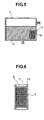
- Fig. 5 is a view for showing the condition, in a case where the ion exchange bag is located at the predetermined position within the tank.
- the ion exchange bag 9 will not comes up to the surface if a gaseous layer remains in an inside thereof, thereby enabling to adsorb the corrosive ions within the cooling liquid. Also, with provision of the partition plate 13 at the central portion of the tank 5, it is possible to hold the ion exchange bag 9 within the cooling liquid if the cooling system is used in any posture thereof. For this reason, the corrosive ions within the cooling liquid can pass through the water-permeable bag together with the cooling liquid, to be adsorbed by the ion exchange resin within the bag.
- Fig. 6 is a view for showing other embodiment of the ion. exchange bag therein.
- the water-permeable bag 12 having a hole 14 for use of fixing thereof, can be holed within the liquid, but without floating up when a gaseous layer is formed within the bag because of the low water-permeability thereof. For this reason, the corrosive ions within the cooling liquid can pass through the water-permeable bag together with the cooling liquid, to be adsorbed by the ion exchange resin within the bag.
- Fig. 7 is a view for showing further other embodiment of the ion exchange bag therein.
- the water-permeable bag 12, having a weight 15 for use of prevention of floating can be held within the liquid, but without floating up even if a gaseous layer is formed therein because of the low water-permeability thereof.
- the ion exchange bag can be held within the liquid when the cooling system is used in any posture thereof. For this reason, the corrosive ions within the cooling liquid can pass through the water-permeable bag together with the cooling liquid, to be adsorbed by the ion exchange resin within the bag.
- the tank is made of a metal, such as, iron, the weight 15 can be attached, easily if making it from a permanent magnet.
- Fig. 8 is a view for showing an example of an ion exchange holder 16 therein.
- the ion exchange holder 16 has the ion exchange bag 9, a part for holing that ion exchange bag 9 therein, and a part 18 to be fixed onto a part of cooling parts (such as, the tank).
- the part for holding the ion exchange bag 9 therein is made of a metal mesh, for example, and the part 18 to be fixed onto the cooling part is a flange, for example.
- the flange has a function of sealing up therethrough, with using such as, packing or an "O" ring, for example.
- the ion exchange holder 16 has an advantage that the ion exchange bag can be exchanged, easily, when the capacity of adsorbing the corrosive ions is reduced down due to the degradation of the ion exchange resin. Also, using of the holder in common with, as a water supply opening, brings about an advantage that the water can be supply in addition, easily when the cooling liquid is lowered down in the amount thereof.
- Fig. 9 is a view for showing an example, in which the ion exchange holder 16 is installed in the tank 5.
- the ion exchange holder 16 is located in the vicinity of the center of the tank, the ion exchange holder can be held within the cooling liquid if the cooling system is used in any posture thereof. For this reason, the corrosive ions within the cooling liquid can pass through the water-permeable bag together with the cooling water, thereby being adsorbed by the ion exchange resin within the bag.
- Fig. 10 is a view for showing other embodiment of the ion exchange holder 16 therein.
- the water-permeable bag 12 attached with the anti-floating weight 15 is fixed on a fixing part 18, such as, the flange, etc., with us ing the fixing hole 14.
- the ion exchange bag 14 is soft, therefore the ion exchange bag can be held within the cooling liquid even if the cooling system is used in any posture thereof. For this reason, the corrosive ions within the cooling liquid can pass through the water-permeable bag together with the cooling liquid, to be adsorbed by the ion exchange resin within the bag.
- Fig. 11 is a view for showing other embodiment of the ion exchange holder 16, therein.
- Fig. 12 is a view for showing an embodiment, in which the ion exchange holder 16 is inserted into a container having a connect opening thereof.
- the ion exchange holder 15 is attached onto the container 19 having the connect opening between the conduit 3.
- the ion exchange holder 16 does not block the flow passage of the cooling liquid, therefore there is caused no such the pressure loss within the ion exchange holder 16.
- the ion exchange holder 16 can be replaced with the ion exchange bag 9, easily, when the capacity of adsorbing the ions falls down due to the degradation of the ion exchange resin.
- Fig. 13 is a view for showing an embodiment, in which the ion exchange holder 16 and the container having the connect opening with the conduit are formed into a one body.
- the ion exchange holder 16 and the container having the connect opening with the conduit may be formed into a one body, as is shown in the present embodiment.
- Those ion exchange holders 16 show a large effect, in particular, when they are positioned in an upstream of the heat-receiving jacket, for example, being made of the material in need of corrosion control thereof, since it can adsorb those ions, easily.
- Fig. 14 shows an example of building up the container 19 with using a conduit 20 having a small capillary in a part thereof and also a cover 21.
- This container can be manufacture through the drawing process, easily, thereby obtaining a low cost thereof.
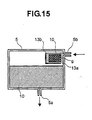
- Fig. 15 is a view for showing the ion exchange bag 9 or the ion exchange holder 16, being disposed within the tank.
- a partition plate 13 around the periphery of the ion exchange bag 9 is provided a partition plate 13.
- the cooling liquid flows into an inside of the tank from a discharge opening 5b, and is stayed or accumulated within the partition plate.
- the cooling liquid accumulted within the partition plate drips down from a drip opening 13a opened in the partition plate, gradually. Due to the flow of the cooling liquid dripping therefrom, the corrosive ions within the cooling liquid are adsorbed on the ion exchange resin within the ion exchange bag 9 or the ion exchange holder 16, with superior or high efficiency.
- the cooling liquid flowing into the tank 5 overflows from an overflow opening 13b formed in the partition plate.
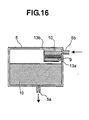
- Fig. 16 shows an example, in which the drip opening 13a of the partition plate and the ion exchange bag 9 or the ion exchange holder 16 are disposed in series.
- the liquid cooling system or an electronic apparatus using the same therein, enabling to maintain the corrosion resistance for a long time period (from 5 to 10 years) suitable for the electronic apparatus, which has the heat-generation body therein, such as, the semiconductor element, being microminiaturized and very thin in the thickness and also having a large amount of heat-generation thereof.
Landscapes
- Engineering & Computer Science (AREA)
- Architecture (AREA)
- Civil Engineering (AREA)
- Structural Engineering (AREA)
- Theoretical Computer Science (AREA)
- Computer Hardware Design (AREA)
- Human Computer Interaction (AREA)
- Physics & Mathematics (AREA)
- General Engineering & Computer Science (AREA)
- General Physics & Mathematics (AREA)
- Cooling Or The Like Of Electrical Apparatus (AREA)
- Cooling Or The Like Of Semiconductors Or Solid State Devices (AREA)
Applications Claiming Priority (2)
| Application Number | Priority Date | Filing Date | Title |
|---|---|---|---|
| JP2003299430 | 2003-08-25 | ||
| JP2003299430A JP2005072216A (ja) | 2003-08-25 | 2003-08-25 | 液冷システムおよびこれを用いた電子機器 |
Publications (2)
| Publication Number | Publication Date |
|---|---|
| EP1511369A2 true EP1511369A2 (de) | 2005-03-02 |
| EP1511369A3 EP1511369A3 (de) | 2009-01-07 |
Family
ID=34101145
Family Applications (1)
| Application Number | Title | Priority Date | Filing Date |
|---|---|---|---|
| EP04005161A Withdrawn EP1511369A3 (de) | 2003-08-25 | 2004-03-04 | Flüssigkeits-Kühlsystem und elektronischer Gerät mit diesem system |
Country Status (6)
| Country | Link |
|---|---|
| US (1) | US7296618B2 (de) |
| EP (1) | EP1511369A3 (de) |
| JP (1) | JP2005072216A (de) |
| KR (1) | KR20050022245A (de) |
| CN (1) | CN1591851A (de) |
| TW (1) | TWI289647B (de) |
Families Citing this family (8)
| Publication number | Priority date | Publication date | Assignee | Title |
|---|---|---|---|---|
| JP2006057920A (ja) * | 2004-08-20 | 2006-03-02 | Hitachi Ltd | 電子機器の液冷システム、及び、これを用いた電子機器 |
| JP2006261457A (ja) * | 2005-03-17 | 2006-09-28 | Fujitsu Ltd | 受熱体、受熱装置及び電子機器 |
| JP4439441B2 (ja) * | 2005-07-01 | 2010-03-24 | 富士通株式会社 | 熱交換器 |
| JP2008103263A (ja) * | 2006-10-20 | 2008-05-01 | Denso Corp | 燃料電池システム |
| US20110186266A1 (en) * | 2010-02-01 | 2011-08-04 | Suna Display Co. | Heat transfer device with anisotropic thermal conducting structures |
| US8711563B2 (en) * | 2011-10-25 | 2014-04-29 | International Business Machines Corporation | Dry-cooling unit with gravity-assisted coolant flow |
| US9831641B2 (en) * | 2013-03-15 | 2017-11-28 | G-Ro Technologies, Llc | Variable ion generation and delivery |
| JP7478528B2 (ja) * | 2019-10-09 | 2024-05-07 | 株式会社荏原製作所 | キャンドモータポンプ |
Family Cites Families (8)
| Publication number | Priority date | Publication date | Assignee | Title |
|---|---|---|---|---|
| US2917685A (en) * | 1957-07-01 | 1959-12-15 | Ite Circuit Breaker Ltd | Recirculating water system for cooling electrical components |
| US3965000A (en) * | 1972-11-16 | 1976-06-22 | Industrial Filter & Pump Mfg. Co. | Method for operating ion exchange columns |
| JPH0682941B2 (ja) * | 1987-10-22 | 1994-10-19 | 富士通株式会社 | 冷却液供給装置 |
| JPH06342990A (ja) * | 1991-02-04 | 1994-12-13 | Internatl Business Mach Corp <Ibm> | 統合冷却システム |
| US5572538A (en) * | 1992-01-20 | 1996-11-05 | Miyachi Technos Corporation | Laser apparatus and accessible, compact cooling system thereof having interchangeable flow restricting members |
| US5406807A (en) * | 1992-06-17 | 1995-04-18 | Hitachi, Ltd. | Apparatus for cooling semiconductor device and computer having the same |
| JP2002099356A (ja) * | 2000-09-21 | 2002-04-05 | Toshiba Corp | 電子機器用冷却装置および電子機器 |
| JP2003185321A (ja) * | 2001-12-14 | 2003-07-03 | Tada Denki Kk | 純水冷却装置 |
-
2003
- 2003-08-25 JP JP2003299430A patent/JP2005072216A/ja active Pending
-
2004
- 2004-02-25 TW TW093104812A patent/TWI289647B/zh not_active IP Right Cessation
- 2004-03-03 KR KR1020040014160A patent/KR20050022245A/ko not_active Ceased
- 2004-03-04 EP EP04005161A patent/EP1511369A3/de not_active Withdrawn
- 2004-03-04 US US10/791,823 patent/US7296618B2/en not_active Expired - Fee Related
- 2004-03-05 CN CNA2004100077705A patent/CN1591851A/zh active Pending
Also Published As
| Publication number | Publication date |
|---|---|
| TW200508555A (en) | 2005-03-01 |
| US20050047091A1 (en) | 2005-03-03 |
| KR20050022245A (ko) | 2005-03-07 |
| EP1511369A3 (de) | 2009-01-07 |
| TWI289647B (en) | 2007-11-11 |
| US7296618B2 (en) | 2007-11-20 |
| CN1591851A (zh) | 2005-03-09 |
| JP2005072216A (ja) | 2005-03-17 |
Similar Documents
| Publication | Publication Date | Title |
|---|---|---|
| CN100413390C (zh) | 电子设备的液冷系统和使用它的电子设备 | |
| US20060157225A1 (en) | High turbulence heat exchanger | |
| JP6046294B1 (ja) | 処理機および再生機 | |
| US7296618B2 (en) | Liquid cooling system and electronic apparatus using the same | |
| TW201210439A (en) | Extruded server case | |
| TWI749813B (zh) | 液體冷卻系統及裝置 | |
| CN206686504U (zh) | 热管水冷散热装置 | |
| US9310113B2 (en) | Thermoelectric heat pump apparatus | |
| CN108471699A (zh) | 一种深海电源散热系统 | |
| CN114916192A (zh) | 胶囊换热器、液冷罐及液冷系统 | |
| JP2005072216A5 (de) | ||
| CN118099113A (zh) | 一种可更换散热模块的晶上系统散热装置 | |
| JP2005009837A (ja) | 蓄熱装置 | |
| CN210292917U (zh) | 一种换热模块及空调衣 | |
| US10935321B2 (en) | Energy transfer systems and energy transfer methods | |
| JP2959951B2 (ja) | 液循環式恒温装置 | |
| JPH08210748A (ja) | 冷却器 | |
| CN111854467A (zh) | 一种换热模块及空调衣 | |
| JP7675857B2 (ja) | タンク、および給湯機 | |
| KR100741478B1 (ko) | 반도체 공정액 항온기 | |
| WO2012082115A1 (en) | Polishing head retaining ring | |
| BR102012026490A2 (pt) | Sistema de transferência térmica para líquidos por meio direto, e reservatório provido de sistema de transferência térmica direta para líquidos | |
| JP3369770B2 (ja) | 流体用冷却器 | |
| JP2002189536A (ja) | 液冷システムおよび液冷システムを用いたパーソナルコンピュータ | |
| CN120741325A (zh) | 冷却液检测装置 |
Legal Events
| Date | Code | Title | Description |
|---|---|---|---|
| PUAI | Public reference made under article 153(3) epc to a published international application that has entered the european phase |
Free format text: ORIGINAL CODE: 0009012 |
|
| AK | Designated contracting states |
Kind code of ref document: A2 Designated state(s): AT BE BG CH CY CZ DE DK EE ES FI FR GB GR HU IE IT LI LU MC NL PL PT RO SE SI SK TR |
|
| AX | Request for extension of the european patent |
Extension state: AL LT LV MK |
|
| PUAL | Search report despatched |
Free format text: ORIGINAL CODE: 0009013 |
|
| AK | Designated contracting states |
Kind code of ref document: A3 Designated state(s): AT BE BG CH CY CZ DE DK EE ES FI FR GB GR HU IE IT LI LU MC NL PL PT RO SE SI SK TR |
|
| AX | Request for extension of the european patent |
Extension state: AL LT LV MK |
|
| RIC1 | Information provided on ipc code assigned before grant |
Ipc: H05K 7/20 20060101ALI20081128BHEP Ipc: G06F 1/20 20060101AFI20081128BHEP |
|
| 17P | Request for examination filed |
Effective date: 20090130 |
|
| AKX | Designation fees paid |
Designated state(s): DE |
|
| 17Q | First examination report despatched |
Effective date: 20101203 |
|
| STAA | Information on the status of an ep patent application or granted ep patent |
Free format text: STATUS: THE APPLICATION IS DEEMED TO BE WITHDRAWN |
|
| 18D | Application deemed to be withdrawn |
Effective date: 20110414 |