EP1511183B1 - Tragbares drahtloses endgerät - Google Patents
Tragbares drahtloses endgerät Download PDFInfo
- Publication number
- EP1511183B1 EP1511183B1 EP03730801A EP03730801A EP1511183B1 EP 1511183 B1 EP1511183 B1 EP 1511183B1 EP 03730801 A EP03730801 A EP 03730801A EP 03730801 A EP03730801 A EP 03730801A EP 1511183 B1 EP1511183 B1 EP 1511183B1
- Authority
- EP
- European Patent Office
- Prior art keywords
- antenna
- section
- lower housing
- housing
- finger
- Prior art date
- Legal status (The legal status is an assumption and is not a legal conclusion. Google has not performed a legal analysis and makes no representation as to the accuracy of the status listed.)
- Expired - Lifetime
Links
Images


Classifications
-
- H—ELECTRICITY
- H01—ELECTRIC ELEMENTS
- H01Q—ANTENNAS, i.e. RADIO AERIALS
- H01Q1/00—Details of, or arrangements associated with, antennas
- H01Q1/08—Means for collapsing antennas or parts thereof
- H01Q1/084—Pivotable antennas
-
- H—ELECTRICITY
- H04—ELECTRIC COMMUNICATION TECHNIQUE
- H04B—TRANSMISSION
- H04B1/00—Details of transmission systems, not covered by a single one of groups H04B3/00 - H04B13/00; Details of transmission systems not characterised by the medium used for transmission
- H04B1/38—Transceivers, i.e. devices in which transmitter and receiver form a structural unit and in which at least one part is used for functions of transmitting and receiving
-
- H—ELECTRICITY
- H01—ELECTRIC ELEMENTS
- H01Q—ANTENNAS, i.e. RADIO AERIALS
- H01Q1/00—Details of, or arrangements associated with, antennas
- H01Q1/12—Supports; Mounting means
- H01Q1/22—Supports; Mounting means by structural association with other equipment or articles
- H01Q1/24—Supports; Mounting means by structural association with other equipment or articles with receiving set
- H01Q1/241—Supports; Mounting means by structural association with other equipment or articles with receiving set used in mobile communications, e.g. GSM
- H01Q1/242—Supports; Mounting means by structural association with other equipment or articles with receiving set used in mobile communications, e.g. GSM specially adapted for hand-held use
- H01Q1/243—Supports; Mounting means by structural association with other equipment or articles with receiving set used in mobile communications, e.g. GSM specially adapted for hand-held use with built-in antennas
Definitions
- Portable wireless terminals for communication between mobile units such as a mobile phone (in the present specification, a terminal apparatus is simply referred to as a terminal) tend to have a reduced size and thickness.
- an antenna section mounted on the terminal is closer to a human body during a telephone call, so that concerns are rising that antenna radiation characteristics are degraded.
- terminals which employ an accommodation/extension type of whip antenna provided externally to the terminal instead of terminals which employ an accommodation/extension type of whip antenna provided externally to the terminal, terminals which employ a so-called built-in antenna provided inside the terminal have come on the market as an antenna having advantages such as a low probability of breakage resulting from a drop or the like or the ability to improve design of the portable wireless terminal.
- WO-A-99/43041 discloses the use of an internal substrate antenna in a wireless device in which a parasitic element is used to improve energy coupling characteristics. It goes without saying that degradation of characteristics caused by a human body is also a concern in the terminal employing the built-in antenna.
- the clamshell type terminal generally has a receiver section and a liquid crystal display section provided in an upper housing unit and a keyboard section and a microphone section provided in a lower housing unit.
- a position where an antenna is provided is often (1) an upper portion of the upper housing or (2) an upper portion of the lower housing (that is, a hinge section).
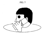
- the hinge section provided type antenna While the distance between the antenna and the head of a human body is long during a telephone call, a user often holds the lower housing or the boundary between the upper and lower housings (that is, near the hinge section) for the call, so that the antenna section is close to a hand or fingers of the user.
- the keyboard section is generally provided in the lower housing unit as described above, the antenna section is also closer to the hand of the user when the user manipulates the keyboard.
- the hinge section provided type antenna has the disadvantage in terms of the antenna characteristics that, when the portion of the housing including the antenna projects, the user conveniently uses the terminal by putting his finger on the projected portion since his hand is stable.
- An example of a mobile phone with a speaker on the front of the housing is D1: JP-2002-141287-A .
- Fig. 11 shows a side view of a conventional clamshell type of mobile phone having an upper housing and a lower housing connected through a hinge section.
- a speaker section abuts on or is close to the placing surface.
- the speaker section abuts on or is close to the placing surface, so that a magnetic substance may be absorbed due to magnetism of the speaker, or dust or the like may enter a number of holes provided in the sound emitting port. This problem applies to a so-called stick type of mobile phone.
- a speaker section may be lifted separately from a placing surface when the mobile phone is placed on a desk or the like.
- the size of open space formed between the housing and the placing surface for transmitting sound from the speaker is tilted in some directions, so that the problem occurs that sound is not necessarily radiated in the surroundings uniformly.
- a portable wireless terminal having a hinge section provided type antenna suitable for a clamshell type which can maintain spacing from the head of a human body and alleviate the influence of the hand of a user.
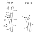
- the portable wireless terminal according to the present invention is defined by a clamshell type portable wireless terminal having an upper housing and a lower housing connected to each other through a hinge, comprising: a projection section that projects outward near a hinge section of the lower housing; a built-in antenna housed in the projection section and having an antenna element in a linear or plate shape, the antenna element being formed of a first element portion having a base end side connected to a feed point and a second element portion which defines an open end side; and a sound emitting port of a speaker on a back side of the lower housing, the speaker being operable to generate a ringtone, in which: the second element portion has a main surface that forms a predetermined angle with a main surface of the first element portion; the second element portion is connected to a side portion
- the portable wireless terminal Since the portable wireless terminal has the built-in antenna housed in the projection section near the hinge section of the clamshell type portable wireless terminal, space for providing the antenna can be ensured. In addition, a relatively long distance between the antenna and the head is maintained during a telephone call. Furthermore, since a user often makes a call by holding a portion near the hinge section, the hand or finger of the user is closer to the antenna section in this structure. However, the antenna open end portion of the antenna element which is likely to be effected by a human body particularly is disposed at a position which is unlikely to be covered by the hand or finger of the user, thereby significantly reducing degradation of antenna characteristics when the terminal is used.
- the single antenna element has surfaces at different angles. This structure avoids a situation in which both main surfaces are simultaneously covered by the hand or finger of the user depending on how the user holds the housing.
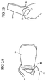
- Fig. 2A shows the external appearance of the terminal when the terminal 100 in the opened state shown in Fig. 1A is viewed from an outward upper direction (1).
- Fig. 2B shows the external appearance of the terminal when the terminal 100 in the same state is viewed from an outward side direction (2). Both figures show the state in which the lower housing 20 is hold by a hand (a left hand) of a user. As seen from these figures, the projection section 30 is formed to extend in a width direction of the housing of the terminal 100.
- This clamshell type terminal has the structure in which fingers are easily put on the projection section (antenna area) 30 having the antenna provided therein.
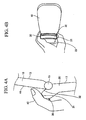
- fingers are easily put on the projection section 30 as shown in Fig. 3B , not in the state in which the projection section 30 is exposed as shown in Fig. 2A and Fig. 2B or Fig. 3A .
- a thumb may be put on the projection section as shown in Fig. 6A and Fig. 6B
- a finger other than the thumb for example, a forefinger
- Whether or not the finger is likely to put on the portion of the housing relates to the size of the area of the surface of an antenna element covered by the finger depending on the structure and arrangement of the antenna element positioned inside.
- "unlikely to be covered” means that this area is reduced. While the outline shape of the projection section is shown as a polygonal line in the figures, the shape as shown is not necessarily used.
- Fig. 4B shows both of the surfaces 31 and 32 in the external appearance of an actual terminal.
- an antenna element 52 in a linear or plate shape is disposed along the inner wall of the surface (A) 31 shown in Fig. 4A and Fig. 4B to separate the antenna element 52 from a ground 56 within the lower housing as much as possible.
- a linear or plate shape thin plate shape
- the hand or finger of a user is most likely put on the surface (A) 31.
- the antenna surface is covered by the finger as shown in Fig. 5C , and it is thought that significant degradation of the antenna characteristics occurs.
- the present invention is not limited thereto, and separate elements 53 and 54 may be conductively bonded. Alternatively, they may be formed by metal foil, not by the metal sheet.
- the element portion 53 on the feed point side is disposed along the inner wall surface of the surface (A) 31 which is the upper surface of the projection section 30, and only the element portion 54 on the open end side is disposed along the inner wall surface of the surface (B) 32 on which the hand or finger of a user is hardly to be put. This is because, even in a single antenna element, a portion with a high impedance generally presents greater degradation of characteristics when the portion is covered by the hand or finger than a portion with a low impedance.
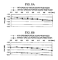
- the structure in Figs. 5A, 5C, and 5E has the substantially equal characteristics to the structure in Figs. 5B, 5D, and 5F .
- the results when the finger is put on the side of the antenna open end has a difference of as much as 4 dB between both structures.
- the structure of the present embodiment in Figs. 5B, 5D, and 5F shows degradation of only 1 dB as compared with when the finger is put on the side of the antenna feed point, while the structure in Figs. 5A, 5C, and 5E shows significant degradation. From the facts, the significance of the influence when the finger is put on the side of the antenna open end can be seen.
- the escape structure of the antenna open end portion which is the high impedance portion, from the hand or finger of the user can significantly reduce degradation of the antenna radiation characteristics when the finger is put on the portion where the antenna is provided.
- Fig. 10A to Fig. 10C show the structure of the mobile phone according to an embodiment of the present invention.
- Fig. 10A is a diagram showing the state in which the mobile phone is folded and placed on a placing surface 40 from the front.
- Fig. 10B is a diagram showing the state from the back.
- Fig. 10C is a diagram showing the state from the side.
- This is a clamshell type mobile phone and has the upper housing 10 and the lower housing 20 connected to be foldable through the hinge 15 as described above.
- the view seen from the front means a view seen from the side of the hinge 15.
- the mobile phone in the present embodiment has the projection section 30 on the front end of the lower housing 20, that is, on the side of the hinge 15, as described above.
- the projection section 30 extends in the width direction of the housing as apparent in Fig. 10A .
- the projection section 30 is in contact with the placing surface 40 linearly at its lower end.
- the rear end side of the lower housing 20 is also in contact with the placing surface 40 at its lower end linearly.
- the mobile phone is placed stably on the placing surface 40 in a plane shape.
- a space is formed between the lower housing 20 and the placing surface 40 in the state in which the mobile phone is placed on the placing surface 40.
- This space forms an opening section 63 which is laterally symmetric, that is, has the equal sizes and shapes on both side portions of the housing.
- Fig. 13A to Fig. 13C show the structure of a mobile phone according to a second embodiment of the present invention. While this is similar to the mobile phone of the first embodiment except for the following point.
- projection sections 61 at an end of a lower housing 20 on the side of a hinge have two separate parts and an opening section 62 is formed between them on a placing surface 40. While the projection section 30 of the first embodiment is in contact with the placing surface 40 linearly, each of the projections 61 of the present embodiment is in contact with the placing surface 40, so to speak, in a point form.
- the end portion on the opposite side to the hinge section of the lower housing 20 is in direct contact with the placing surface without projection.
- An opening section 63 symmetric on both sides is formed identically to the first embodiment.
- An element 16 such as a sub display section or an incoming LED is disposed on the main surface on the outer side of the upper housing 10 as an example.
- this element 16 is not essential in the present invention.
- an antenna member for example a helical antenna, can be fixedly disposed in at least one of them. This allows effective use of the space occupied by the projection section.
- Each antenna as described in the first or second embodiment can be also housed or disposed in a projection section depending on the form of the projection section in the following embodiments.
- Figs. 14A to 14C shows the structure of a mobile phone according to a third embodiment of the present invention. While this is similar to the mobile phone of the second embodiment except for the following point. Specifically, projection sections 64 in two separate parts are also provided at an end portion on the opposite side to an end portion on the side of a hinge of a lower housing 20. This forms an opening section 65 symmetric on both sides on a placing section 40 and forms an opening 62 which is substantially symmetric in the front-to-back direction. Since the space below a speaker section 18 is released in fourth directions of the front, back, left, and right in this embodiment, sound can be transmitted in the surroundings more uniformly as compared with the second embodiment.
- Fig. 15A to Fig. 15C shows the structure of a mobile phone according to a fourth embodiment of the present invention. While this is similar to the mobile phone of the third embodiment except for the following point. Specifically, projection sections 81 and 82 are provided to extend in the width direction at both end portions on the side of a hinge and the opposite side of a lower housing 20. This forms an opening section 84 symmetric on both sides on a placing section 40. Since the space below a speaker section 18 is released in two directions of the left and right in this embodiment, sound can be transmitted in the surroundings more uniformly than the conventional one.
- Fig. 16A to Fig. 16C shows the structure of a mobile phone according to a fifth embodiment of the present invention. While this is similar to the mobile phone of the first embodiment except for the following point. Specifically, a projection section 81 is provided to extend in the width direction at an end portion on the opposite side to an end portion on the side of a hinge of a lower housing 20. The end portion on the side of the hinge section of the lower housing 20 is in direct contact with a placing surface without projection. This forms an opening section 94 symmetric on both sides on a placing section 40. Since the space below a speaker section 18 is released in two directions of the left and right in this embodiment, sound can be transmitted in the surroundings more uniformly than the conventional one.
- Fig. 17A to Fig. 17C shows the structure of a mobile phone according to a sixth embodiment of the present invention. While this is similar to the mobile phone of the fifth embodiment except for the following point. Specifically, projection sections 101 in two separate parts are provided at an end portion on the opposite side to an end portion on the side of a hinge of a lower housing 20. The end portion on the side of the hinge section of the lower housing 20 is in direct contact with a placing surface without projection. This forms an opening section 63 symmetric on both sides and forms an opening section 62 on the rear side on a placing section 40. Since the space below a speaker section 18 is released in three directions of the left and right in this embodiment, sound can be transmitted in the surroundings more uniformly as compared with the fifth embodiment.
- Fig. 18A to Fig. 18C shows the structure of a mobile phone according to a seventh embodiment of the present invention.
- This is a mobile phone which has a projection section 116 accommodating a whip antenna 114 and has a projection section 111 with the equal size to this projection on the side portion on the opposite side.
- the projection section 111 has no antenna accommodated therein.
- the antenna 114 may be a fixed antenna which cannot be extended.
- This structure allow the mobile phone to be stably placed on a placing surface and forms opening sections 112 symmetric on both sides and an opening section 62 in front in which the space facing a speaker section 18 connects to the surroundings. In other words, the space facing the speaker section 18 is released in three directions of the opening section 62 and the two opening sections 112.
- sound can be transmitted in the surroundings more uniformly than the conventional one.
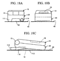
- Fig. 19A to Fig. 19C shows the structure of a mobile phone according to an eighth embodiment of the present invention.
- This is not a clamshell type but a straight type mobile phone.
- Projection sections 113 in separate two parts are provided on the rear side of a housing, that is, on the opposite side to the side where a liquid crystal display section 13 is positioned.
- the projection sections 113 form an opening section 62 opened to the rear side and opening sections 105 opened symmetrically on both sides on a placing surface 40.
- the space facing a speaker section 18 is released in three directions of the opening section 62 and the two opening sections 105.
- the projection section 113 may be formed to extend in the width direction of the housing.
- the built-in antenna is disposed in the projection section of the housing near the hinge section of the clamshell type mobile phone, the advantages of the hinge section provided type antenna are maintained such as a relatively large interval between the built-in antenna and the head of a user during use for a telephone call. Also, the surface of the projection surface forming a predetermined angle with the main surface on the outer side of the upper housing in the opened state is effectively used for arranging at least the open end side of the antenna element, it is possible to alleviate degradation of antenna characteristics which is a disadvantage of the hinge section provided type antenna due to the antenna section approaching a hand or finger of a user.
- the antenna element is formed of the first element portion in a flat plane shape with its base end connected to the feed point and the second element portion in a flat plate shape connecting to the side portion on the end side of the element portion and having a main surface forming a predetermined angle with a main surface of the first element portion.
Landscapes
- Engineering & Computer Science (AREA)
- Computer Networks & Wireless Communication (AREA)
- Signal Processing (AREA)
- Telephone Set Structure (AREA)
Claims (3)
- Tragbares drahtloses Endgerät (100) vom Klapptyp mit einem oberen Gehäuse (10) und einem unteren Gehäuse (20), das mit dem oberen Gehäuse durch ein Gelenk (15) verbunden ist, umfassend:einen Vorsprungsabschnitt (30), der nahe eines Gelenkabschnitts des unteren Gehäuses (20) nach außen vorsteht;eine eingebaute Antenne, die in dem Vorsprungsabschnitt (30) untergebracht ist unddie ein Antennenelement (50) in einer geradlinigen Form oder einer Plattenform aufweist,wobei das Antennenelement (50) aus einem ersten Elementteil (53) mit einer Grundendseite, welche mit einem Speisepunkt (51) verbunden ist, und einem zweiten Elementteil (54) gebildet ist, der bzw. das eine offene Endseite festlegt;
und eine Schallabgabe-Öffnung eines Lautsprechers (18) in einer Rückseite des unteren Gehäuses (20), wobei der Lautsprecher (18) für die Erzeugung eines Klingeltones betreibbar ist;
wobei das zweite Elementteil (54) eine Hauptfläche aufweist, die einen bestimmten Winkel mit einer Hauptfläche des ersten Elementteiles (53) bildet;
wobei das zweite Elementteil (54) mit einem Seitenteil an einer Endseite des ersten Elementteiles (53) verbunden ist;
wobei zumindest ein Teil des Antennenelements auf der offenen Endseite an einer Stelle angeordnet ist, die kaum durch eine Hand oder einen Finger (42) eines Benutzers bedeckt ist, wenn der Benutzer das Endgerät nutzt;
wobei in dem Fall, dass die Rückseite des unteren Gehäuses (20) auf eine eben geformte Fläche (20) gelegt ist, der Vorsprungsabschnitt (30) die Schallabgabeöffnung des Lautsprechers (18) von der eben geformten Fläche (40) zumindest auf beiden Seiten des unteren Gehäuses trennt;
und wobei die Trennung zwischen der Schallabgabeöffnung und der eben geformten Fläche auf beiden Seiten des unteren Gehäuses symmetrisch ist. - Tragbares drahtloses Endgerät nach Anspruch 1, bei dem das Antennenelement durch ein leitendes plattenförmiges Glied gebildet ist, wobei ein mittlerer Bereich des plattenförmigen Gliedes in einer gekröpften Form gefaltet ist.
- Tragbares drahtloses Endgerät nach Anspruch 1, wobei der Vorsprungsabschnitt eine Außenfläche aufweist, die sich in Richtung einer Gehäusebreite erstreckt,
wobei die Außenfläche mit einer äußeren Hauptfläche des oberen Gehäuses einen spitzen Winkel bildet, wenn das obere Gehäuse und das untere Gehäuse geöffnet sind, und wobei das Antennenelement derart angeordnet ist, dass die Hauptfläche des zweiten Elementteiles sich längs einer inneren Wandfläche dieser äußeren Fläche erstreckt.
Applications Claiming Priority (5)
| Application Number | Priority Date | Filing Date | Title |
|---|---|---|---|
| JP2002161078 | 2002-06-03 | ||
| JP2002161078A JP4266100B2 (ja) | 2002-06-03 | 2002-06-03 | 携帯無線端末 |
| JP2002237969 | 2002-08-19 | ||
| JP2002237969A JP4136533B2 (ja) | 2002-08-19 | 2002-08-19 | 携帯通信端末装置 |
| PCT/JP2003/007022 WO2003103173A1 (ja) | 2002-06-03 | 2003-06-03 | 携帯無線端末 |
Publications (3)
| Publication Number | Publication Date |
|---|---|
| EP1511183A1 EP1511183A1 (de) | 2005-03-02 |
| EP1511183A4 EP1511183A4 (de) | 2005-08-31 |
| EP1511183B1 true EP1511183B1 (de) | 2008-10-01 |
Family
ID=29714322
Family Applications (1)
| Application Number | Title | Priority Date | Filing Date |
|---|---|---|---|
| EP03730801A Expired - Lifetime EP1511183B1 (de) | 2002-06-03 | 2003-06-03 | Tragbares drahtloses endgerät |
Country Status (6)
| Country | Link |
|---|---|
| US (2) | US7082324B2 (de) |
| EP (1) | EP1511183B1 (de) |
| KR (1) | KR100973624B1 (de) |
| CN (1) | CN1543713B (de) |
| DE (1) | DE60323833D1 (de) |
| WO (1) | WO2003103173A1 (de) |
Families Citing this family (30)
| Publication number | Priority date | Publication date | Assignee | Title |
|---|---|---|---|---|
| US7031762B2 (en) * | 2000-12-28 | 2006-04-18 | Mitsubishi Denki Kabushiki Kaisha | Mobile terminal including first and second housings and an antenna |
| WO2003103173A1 (ja) * | 2002-06-03 | 2003-12-11 | ソニー・エリクソン・モバイルコミュニケーションズ株式会社 | 携帯無線端末 |
| EP1445821A1 (de) * | 2003-02-06 | 2004-08-11 | Matsushita Electric Industrial Co., Ltd. | Tragbares Funkkommunikationsgerät mit einem Auslegerteil |
| FI115573B (fi) * | 2003-06-11 | 2005-05-31 | Filtronic Lk Oy | Taitettavan radiolaitteen antenni |
| JP2005303542A (ja) * | 2004-04-08 | 2005-10-27 | Fujitsu Ltd | 無線通信装置 |
| TWI239751B (en) * | 2004-05-28 | 2005-09-11 | Benq Corp | Foldable electronic device |
| US8633864B2 (en) | 2004-06-21 | 2014-01-21 | Motorola Mobility Llc | Antenna having an antenna to radome relation which minimizes user loading effect |
| USD518012S1 (en) * | 2004-09-16 | 2006-03-28 | Siemens Aktiengesellschaft | Mobile phone |
| USD518013S1 (en) * | 2004-09-16 | 2006-03-28 | Siemens Aktiengesellschaft | Mobile phone |
| JP4159533B2 (ja) * | 2004-10-28 | 2008-10-01 | 埼玉日本電気株式会社 | 携帯電話機、携帯電話機の製造方法 |
| USD536318S1 (en) * | 2004-12-10 | 2007-02-06 | Samsung Electronics Co., Ltd. | Cellular phone |
| KR100671302B1 (ko) | 2005-03-08 | 2007-01-19 | 삼성전자주식회사 | 모바일 디스플레이장치 |
| USD523833S1 (en) * | 2005-03-29 | 2006-06-27 | Samsung Electronics Co., Ltd. | Portable telephone |
| USD540766S1 (en) * | 2005-04-05 | 2007-04-17 | Samsung Electronics Co., Ltd. | Portable telephone |
| USD537427S1 (en) * | 2005-04-05 | 2007-02-27 | Samsung Electronics Co., Ltd. | Portable telephone |
| USD552057S1 (en) * | 2005-04-12 | 2007-10-02 | Lg Electronics Inc. | Mobile phone |
| US20060276135A1 (en) * | 2005-06-03 | 2006-12-07 | Accton Technology Corporation | Antenna control method and system |
| USD549680S1 (en) * | 2005-06-22 | 2007-08-28 | Lg Electronics Inc. | Mobile phone |
| US8363012B2 (en) | 2007-07-31 | 2013-01-29 | Microsoft Corporation | Pointing device for interface with a graphical display |
| US20100053084A1 (en) * | 2008-08-27 | 2010-03-04 | Microsoft Corporation | Collapsible mouse with pinch-risk solution |
| USD608331S1 (en) * | 2008-12-04 | 2010-01-19 | Samsung Electronics Co., Ltd. | Mobile phone |
| TWI390942B (zh) * | 2009-05-26 | 2013-03-21 | Htc Corp | 行動通訊裝置 |
| CN101909093B (zh) * | 2009-06-04 | 2013-09-25 | 宏达国际电子股份有限公司 | 移动通讯装置 |
| CN102457787B (zh) * | 2010-10-21 | 2016-05-04 | 鸿富锦精密工业(深圳)有限公司 | 便携式电子装置 |
| US20120321117A1 (en) * | 2010-10-21 | 2012-12-20 | Hon Hai Precision Industry Co., Ltd. | Portable electronic device having sound emission holes aligned with speaker at recess of rear cover |
| US9407984B2 (en) * | 2011-02-24 | 2016-08-02 | Htc Corporation | Method and apparatus for adjusting sound quality |
| KR101731375B1 (ko) * | 2015-11-20 | 2017-04-28 | 엘지전자 주식회사 | 이동 단말기 |
| CN106067593B (zh) * | 2016-08-19 | 2020-07-24 | 联想(北京)有限公司 | 一种电子设备和天线控制方法 |
| EP3583482A4 (de) | 2017-04-20 | 2020-11-18 | Hewlett-Packard Development Company, L.P. | Vorrichtungsantennen |
| US20230247349A1 (en) * | 2022-01-28 | 2023-08-03 | Apple Inc. | Electronic device |
Family Cites Families (12)
| Publication number | Priority date | Publication date | Assignee | Title |
|---|---|---|---|---|
| JPH0697713A (ja) * | 1992-07-28 | 1994-04-08 | Mitsubishi Electric Corp | アンテナ |
| US6285327B1 (en) * | 1998-04-21 | 2001-09-04 | Qualcomm Incorporated | Parasitic element for a substrate antenna |
| WO1999043041A1 (en) | 1998-02-20 | 1999-08-26 | Qualcomm Incorporated | Substrate antenna incorporating an element preventing the coupling of energy between antenna and conductors |
| GB2344969B (en) * | 1998-12-19 | 2003-02-26 | Nec Technologies | Mobile phone with incorporated antenna |
| JP2001274717A (ja) * | 2000-03-24 | 2001-10-05 | Mitsubishi Electric Corp | 携帯無線機 |
| JP2001284934A (ja) * | 2000-03-28 | 2001-10-12 | Kyocera Corp | 携帯無線機 |
| JP3642261B2 (ja) * | 2000-05-16 | 2005-04-27 | 日本電気株式会社 | 無線端末 |
| CN100559810C (zh) * | 2000-06-30 | 2009-11-11 | 松下电器产业株式会社 | 携带电话机 |
| US20020006809A1 (en) * | 2000-07-14 | 2002-01-17 | Tetsuya Kubo | Portable radio terminal device |
| JP2002125021A (ja) * | 2000-10-13 | 2002-04-26 | Nec Saitama Ltd | 携帯無線端末 |
| JP2002141987A (ja) * | 2000-10-31 | 2002-05-17 | Kyocera Corp | 折畳式携帯無線通信装置 |
| WO2003103173A1 (ja) * | 2002-06-03 | 2003-12-11 | ソニー・エリクソン・モバイルコミュニケーションズ株式会社 | 携帯無線端末 |
-
2003
- 2003-06-03 WO PCT/JP2003/007022 patent/WO2003103173A1/ja not_active Ceased
- 2003-06-03 KR KR1020047001603A patent/KR100973624B1/ko not_active Expired - Fee Related
- 2003-06-03 EP EP03730801A patent/EP1511183B1/de not_active Expired - Lifetime
- 2003-06-03 DE DE60323833T patent/DE60323833D1/de not_active Expired - Lifetime
- 2003-06-03 CN CN038007754A patent/CN1543713B/zh not_active Expired - Fee Related
- 2003-06-03 US US10/485,224 patent/US7082324B2/en not_active Expired - Fee Related
-
2006
- 2006-05-26 US US11/441,640 patent/US7266399B2/en not_active Expired - Fee Related
Also Published As
| Publication number | Publication date |
|---|---|
| EP1511183A1 (de) | 2005-03-02 |
| US7266399B2 (en) | 2007-09-04 |
| WO2003103173A1 (ja) | 2003-12-11 |
| US20050176475A1 (en) | 2005-08-11 |
| US7082324B2 (en) | 2006-07-25 |
| CN1543713B (zh) | 2010-05-12 |
| KR100973624B1 (ko) | 2010-08-02 |
| EP1511183A4 (de) | 2005-08-31 |
| KR20050002795A (ko) | 2005-01-10 |
| US20060217164A1 (en) | 2006-09-28 |
| CN1543713A (zh) | 2004-11-03 |
| DE60323833D1 (de) | 2008-11-13 |
Similar Documents
| Publication | Publication Date | Title |
|---|---|---|
| EP1511183B1 (de) | Tragbares drahtloses endgerät | |
| KR101186094B1 (ko) | 핸드헬드 전자 장치용 안테나 | |
| US5945954A (en) | Antenna assembly for telecommunication devices | |
| KR100652620B1 (ko) | 내장형 안테나가 구비된 휴대용 단말기 | |
| US7187959B2 (en) | Antenna structure for devices with conductive chassis | |
| JP2009118027A (ja) | アンテナ装置の取付構造 | |
| US6725070B2 (en) | Portable radio device | |
| US7840243B2 (en) | Antenna arrangement in a mobile terminal apparatus | |
| US6970728B2 (en) | Extended antenna support for a wireless communications device | |
| CN101385198A (zh) | 便携式无线机 | |
| JP2008227560A (ja) | 携帯無線機 | |
| US8160658B2 (en) | Cellular phone | |
| JP2009188714A (ja) | 携帯電話装置 | |
| EP1646109B1 (de) | Kleine hochintegrierte drahtlose Hör-Sprechgarnitur | |
| JP4266100B2 (ja) | 携帯無線端末 | |
| KR100681759B1 (ko) | 안테나 성능 개선을 위한 도전체를 갖는 휴대용 무선단말기 | |
| JP3715607B2 (ja) | 携帯無線装置 | |
| JP2003037411A (ja) | 携帯用無線機 | |
| JP2004128604A (ja) | 無線通信装置 | |
| JP2006115419A (ja) | 折畳式携帯無線機 | |
| JP2011120228A (ja) | 携帯通信端末 | |
| JP2006050044A (ja) | 開閉式通信端末装置 | |
| JP2004023362A (ja) | 携帯無線機 | |
| JP2003283625A (ja) | 情報通信機器 |
Legal Events
| Date | Code | Title | Description |
|---|---|---|---|
| PUAI | Public reference made under article 153(3) epc to a published international application that has entered the european phase |
Free format text: ORIGINAL CODE: 0009012 |
|
| 17P | Request for examination filed |
Effective date: 20040202 |
|
| AK | Designated contracting states |
Kind code of ref document: A1 Designated state(s): AT BE BG CH CY CZ DE DK EE ES FI FR GB GR HU IE IT LI LU MC NL PT RO SE SI SK TR |
|
| A4 | Supplementary search report drawn up and despatched |
Effective date: 20050715 |
|
| RIC1 | Information provided on ipc code assigned before grant |
Ipc: 7H 01Q 1/00 B Ipc: 7H 04B 1/38 A |
|
| RBV | Designated contracting states (corrected) |
Designated state(s): DE FR GB |
|
| GRAP | Despatch of communication of intention to grant a patent |
Free format text: ORIGINAL CODE: EPIDOSNIGR1 |
|
| GRAS | Grant fee paid |
Free format text: ORIGINAL CODE: EPIDOSNIGR3 |
|
| GRAA | (expected) grant |
Free format text: ORIGINAL CODE: 0009210 |
|
| AK | Designated contracting states |
Kind code of ref document: B1 Designated state(s): DE FR GB |
|
| REG | Reference to a national code |
Ref country code: GB Ref legal event code: FG4D |
|
| REF | Corresponds to: |
Ref document number: 60323833 Country of ref document: DE Date of ref document: 20081113 Kind code of ref document: P |
|
| PLBE | No opposition filed within time limit |
Free format text: ORIGINAL CODE: 0009261 |
|
| STAA | Information on the status of an ep patent application or granted ep patent |
Free format text: STATUS: NO OPPOSITION FILED WITHIN TIME LIMIT |
|
| 26N | No opposition filed |
Effective date: 20090702 |
|
| PGFP | Annual fee paid to national office [announced via postgrant information from national office to epo] |
Ref country code: DE Payment date: 20130620 Year of fee payment: 11 Ref country code: GB Payment date: 20130619 Year of fee payment: 11 |
|
| PGFP | Annual fee paid to national office [announced via postgrant information from national office to epo] |
Ref country code: FR Payment date: 20130703 Year of fee payment: 11 |
|
| REG | Reference to a national code |
Ref country code: DE Ref legal event code: R119 Ref document number: 60323833 Country of ref document: DE |
|
| GBPC | Gb: european patent ceased through non-payment of renewal fee |
Effective date: 20140603 |
|
| REG | Reference to a national code |
Ref country code: DE Ref legal event code: R119 Ref document number: 60323833 Country of ref document: DE Effective date: 20150101 |
|
| REG | Reference to a national code |
Ref country code: FR Ref legal event code: ST Effective date: 20150227 |
|
| PG25 | Lapsed in a contracting state [announced via postgrant information from national office to epo] |
Ref country code: DE Free format text: LAPSE BECAUSE OF NON-PAYMENT OF DUE FEES Effective date: 20150101 |
|
| PG25 | Lapsed in a contracting state [announced via postgrant information from national office to epo] |
Ref country code: GB Free format text: LAPSE BECAUSE OF NON-PAYMENT OF DUE FEES Effective date: 20140603 Ref country code: FR Free format text: LAPSE BECAUSE OF NON-PAYMENT OF DUE FEES Effective date: 20140630 |