EP1511157B1 - Elektromotor - Google Patents
Elektromotor Download PDFInfo
- Publication number
- EP1511157B1 EP1511157B1 EP04017105.0A EP04017105A EP1511157B1 EP 1511157 B1 EP1511157 B1 EP 1511157B1 EP 04017105 A EP04017105 A EP 04017105A EP 1511157 B1 EP1511157 B1 EP 1511157B1
- Authority
- EP
- European Patent Office
- Prior art keywords
- sensors
- fan wheel
- rotor
- ring
- asynchronous motor
- Prior art date
- Legal status (The legal status is an assumption and is not a legal conclusion. Google has not performed a legal analysis and makes no representation as to the accuracy of the status listed.)
- Expired - Lifetime
Links
- 238000011156 evaluation Methods 0.000 claims description 12
- 239000004033 plastic Substances 0.000 claims description 8
- 238000000034 method Methods 0.000 claims description 4
- 239000002245 particle Substances 0.000 claims description 4
- 238000001816 cooling Methods 0.000 description 4
- 229910000859 α-Fe Inorganic materials 0.000 description 4
- 230000005540 biological transmission Effects 0.000 description 2
- 230000005415 magnetization Effects 0.000 description 2
- 239000000463 material Substances 0.000 description 2
- 238000004026 adhesive bonding Methods 0.000 description 1
- 230000004888 barrier function Effects 0.000 description 1
- 238000005266 casting Methods 0.000 description 1
- 238000010276 construction Methods 0.000 description 1
- 238000011109 contamination Methods 0.000 description 1
- 230000001419 dependent effect Effects 0.000 description 1
- 238000001514 detection method Methods 0.000 description 1
- 238000005538 encapsulation Methods 0.000 description 1
- 210000003746 feather Anatomy 0.000 description 1
- 239000003292 glue Substances 0.000 description 1
- 238000002347 injection Methods 0.000 description 1
- 239000007924 injection Substances 0.000 description 1
- 239000002184 metal Substances 0.000 description 1
- 239000000843 powder Substances 0.000 description 1
- 230000002441 reversible effect Effects 0.000 description 1
- 239000004065 semiconductor Substances 0.000 description 1
- 229920005992 thermoplastic resin Polymers 0.000 description 1
- 238000004804 winding Methods 0.000 description 1
Images

Classifications
-
- H—ELECTRICITY
- H02—GENERATION; CONVERSION OR DISTRIBUTION OF ELECTRIC POWER
- H02K—DYNAMO-ELECTRIC MACHINES
- H02K11/00—Structural association of dynamo-electric machines with electric components or with devices for shielding, monitoring or protection
- H02K11/20—Structural association of dynamo-electric machines with electric components or with devices for shielding, monitoring or protection for measuring, monitoring, testing, protecting or switching
- H02K11/21—Devices for sensing speed or position, or actuated thereby
- H02K11/225—Detecting coils
-
- H—ELECTRICITY
- H02—GENERATION; CONVERSION OR DISTRIBUTION OF ELECTRIC POWER
- H02K—DYNAMO-ELECTRIC MACHINES
- H02K11/00—Structural association of dynamo-electric machines with electric components or with devices for shielding, monitoring or protection
- H02K11/20—Structural association of dynamo-electric machines with electric components or with devices for shielding, monitoring or protection for measuring, monitoring, testing, protecting or switching
- H02K11/21—Devices for sensing speed or position, or actuated thereby
- H02K11/215—Magnetic effect devices, e.g. Hall-effect or magneto-resistive elements
-
- H—ELECTRICITY
- H02—GENERATION; CONVERSION OR DISTRIBUTION OF ELECTRIC POWER
- H02K—DYNAMO-ELECTRIC MACHINES
- H02K11/00—Structural association of dynamo-electric machines with electric components or with devices for shielding, monitoring or protection
- H02K11/30—Structural association with control circuits or drive circuits
- H02K11/33—Drive circuits, e.g. power electronics
-
- H—ELECTRICITY
- H02—GENERATION; CONVERSION OR DISTRIBUTION OF ELECTRIC POWER
- H02K—DYNAMO-ELECTRIC MACHINES
- H02K5/00—Casings; Enclosures; Supports
- H02K5/04—Casings or enclosures characterised by the shape, form or construction thereof
- H02K5/10—Casings or enclosures characterised by the shape, form or construction thereof with arrangements for protection from ingress, e.g. water or fingers
-
- H—ELECTRICITY
- H02—GENERATION; CONVERSION OR DISTRIBUTION OF ELECTRIC POWER
- H02K—DYNAMO-ELECTRIC MACHINES
- H02K9/00—Arrangements for cooling or ventilating
- H02K9/02—Arrangements for cooling or ventilating by ambient air flowing through the machine
- H02K9/04—Arrangements for cooling or ventilating by ambient air flowing through the machine having means for generating a flow of cooling medium
- H02K9/06—Arrangements for cooling or ventilating by ambient air flowing through the machine having means for generating a flow of cooling medium with fans or impellers driven by the machine shaft
-
- H—ELECTRICITY
- H02—GENERATION; CONVERSION OR DISTRIBUTION OF ELECTRIC POWER
- H02K—DYNAMO-ELECTRIC MACHINES
- H02K9/00—Arrangements for cooling or ventilating
- H02K9/14—Arrangements for cooling or ventilating wherein gaseous cooling medium circulates between the machine casing and a surrounding mantle
Definitions
- the invention relates to an asynchronous motor.
- a speed sensor system is known, which is particularly simple and inexpensive.
- the wings of a fan of an engine are detected by sensors.
- the generated data rate is so low that a cost-effective bus system for transmitting the data can be used.
- the disadvantage here is that the angle resolution depends on the number of fans and is therefore limited.
- the sensors require a lot of space outside the engine.
- the machine has at least one stator housing, a rotor and a fan wheel
- the stator housing comprises a B-bearing flange, in particular for receiving a B-side bearing of the rotor, wherein the fan wheel is connected to the rotor, in particular thus rotates with the rotor, and a ring is connected to the fan wheel on a side of the fan wheel facing the B bearing flange
- an evaluation is releasably connected to the stator housing and sensors are connected to the evaluation and so arranged that the sensors cooperate with the ring such that information about the angular position and / or speed of the rotor by means of a data line can be transmitted from the transmitter.
- a brushless motor in which a power transistor is arranged on a control circuit board, wherein the control circuit board is arranged between a fan and a B-end shield.
- a control method for a reversible motor-generator of a vehicle is known, wherein a data bus comprises lines to Hall sensors and control valves.
- EP 1 156 496 A1 The use of a resin-bonded magnet comprising a ferrite powder and a thermoplastic resin is known.
- the invention is therefore the object of developing a motor that should have a robust and cost-effective encoder system.
- the object is achieved in the electric motor according to the features indicated in claim 1.
- the asynchronous motor comprises at least one stator housing, a rotor and a fan wheel
- the stator housing comprises a B-bearing flange, in particular for receiving a B-side bearing of the rotor
- the fan wheel is connected to the rotor, in particular thus rotates with the rotor
- a ring is connected to the fan wheel on a side of the fan wheel facing the B bearing flange
- an evaluation is releasably connected to the stator housing and sensors are connected to the evaluation and arranged such that the sensors cooperate with the ring such that from the transmitter information about the angular position of the rotor by means of a data line can be transmitted
- the ring (11 ) is designed integrated in the fan wheel (7) and the fan (7) is made of a plastic with magnetizable particles, wherein the fan (7) is alternately magnetized differently on the circumference, said magnetizing takes place at approximately
- the advantage here is that the resolution is not dependent on the number of blades of the fan but is arbitrary selectable.
- the required volume of construction is much smaller and both the sensors and the transmitter and the ring are protected within the fan guard vorsehbar.
- the resolution of the invention Encoder by means of the choice of magnetized areas can be fixed. For example, 12 or even 50 or more areas can be formed. Thus, the invention provides a resolution of 30 ° or even 7.2 ° or less. This is sufficient for a simple industrial positioning task. Thus, even an asynchronous motor can be used as an electric motor for positioning, ie can be used in a positioning drive.
- the sensors are designed as Hall sensors, as Wieganddrähte, as pulse wires or other, magnetic-sensitive sensors.
- the advantage here is that the sensors are insensitive to contamination and / or moisture and temperature compensated providable.
- power supplies are dispensable in the Wiegand or pulse wires.
- the data line runs at least partially in a hybrid cable or can be effected by modulating on power cables.
- the advantage here is that no special cable must be laid, but the power cables that have to be laid anyway, either in modified form as a hybrid cable or in the usual form with Augmodulationsvorraumen be provided. Overall, this is simple and inexpensive and compact executable. In addition, the wiring is simple and robust executable.
- the transmitter processes the signals of the sensors such that data in a bus format, such as fieldbus or the like, can be transmitted via the data line.
- a bus format such as fieldbus or the like
- the data line leads to a power converter, inverter and / or an electronic circuit.
- power converters, converters and / or an electronic circuit for control and / or regulation can use the data on the angular position of the rotor and thereby support the calculations.
- the control and regulation can be formed as positioning control.
- the motor can even be used as an asynchronous motor, in particular in conjunction with an electric work brake.
- an inverter and / or a power converter is provided on the electric motor.
- the advantage here is that such an integrated converter or inverter motor to form a compact robust positioning drive is providable.
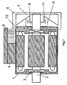
- FIG. 1 is an electric motor in sectional view schematically drawn, which serves to explain the technical background.
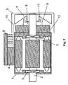
- FIG. 2 is an electric motor with brake, so a brake motor, drawn in sectional view schematically to explain the technical background.
- FIG. 3 shows the embodiment according to FIG. 1 more accurate.
- the electric motor comprises a stator housing 1 and a rotor 2 mounted rotatably relative thereto by means of two bearings 3.
- a terminal box 4 for connection devices is mounted, on which a power converter 6 with cooling device is mounted.
- the electric motor is also executable as a converter motor.
- at least one thermal barrier is provided between the stator windings and the electronics of the power converter or converter.
- the dissipation of the heat generated by the power semiconductors of the power converter or inverter is essentially via the heat sink, the cooling fins in the FIGS. 1 and 2 directed towards the engine. In further embodiments, additionally or alternatively directed away from the engine cooling fins are providable.
- the invention also relates to pure electric motors without converters or converters, said converter or inverter is mounted in the field or in a cabinet and is connected at least with electrical supply lines to the electric motor.
- the rotor 2 is releasably connected to a fan wheel 7 with wings, which is rotatable in a protected area of the fan cover 5 area.
- the fan wheel is connected by means of feather key connection with the rotor shaft of the rotor 2
- a transmitter 8 is detachably connected to the B-bearing flange, comprising sensors.
- a pole ring At the fan 7, a pole ring, so a ring 11 is mounted on the circumference alternating magnetization direction.
- the sensors detect the magnetic field of the ring which is rotatable relative to them and are offset relative to one another at the circumference, as a result of which direction of rotation detection can be realized.
- the pole ring consists of 12 areas, 6 of which have their magnetic north pole facing the sensors, and 6 areas with their south magnetic pole Sensors are turned around, the sensors are advantageously arranged offset by 15 ° on the circumference of the pole ring.
- the transmitter is protected by a surrounding electronics housing 9.
- a protection by encapsulation or casting with a plastic can be achieved.
- the transmitter is connected to a data line 10, which leads to the power converter and this information about the angle of the fan wheel zu lake.
- the data line is also integrated with the supply lines executable.
- the power lines for supplying the motor and signal lines for data transmission and / or transmission of control signals comprises.
- a modulation of the data to be transmitted on the supply lines themselves can be executed.
- the evaluation electronics including sensors and ring thus made compact, protected by the fan guard and in the resolution regardless of the number of fan blades of the impeller 7.
- the ring is executable that not only 12 but 50 or more pulses per revolution providable are.
- FIG. 2 a corresponding embodiment with brake 12 is shown, wherein the evaluation electronics is not arranged between B-bearing flange of the stator housing 1 and fan 7 but between the brake 12 and fan 7.
- the evaluation electronics can be used in a modular system of electric motors, which includes electric motors and motors with brake and inverter motors and inverter motors with brake.
- inverter motors are electric motors with integrated inverter as in the FIGS. 1 and 2 shown schematically.
- the ring is designed so that it can be used in at least two sizes of the series, ie at least two different performance classes of electric motors.
- the fan wheel is designed differently sizes for both sizes, but with the same receptacle for the ring. So it can always be the same ring used in at least two different sized fan wheels of the series. Thus, the number of parts in the series is kept small overall and the storage space and costs are reduced.
- the ring is connected to the fan with Befest onlysklipsen.
- the fan is made of plastic and the ring of ferrite or a ferrite.
- the ring is made of a plastic in which ferrite particles were mixed in before the injection process.
- the fan made of a plastic with magnetizable particles.
- the ring is so to speak executable integrated in the fan.
- the fan wheel is then alternately magnetized differently on the circumference, wherein this magnetization takes place at approximately the radius at which the sensors are arranged.
- the ring is not made of alternately magnetizable material, such as ferromagnet, ferrimagnet and / or permanent magnets, but it is provided a material in which a physical parameter, such as electrical conductivity or dielectric constant or an electrical or magnetic Suzeptibiltician, at the periphery of the ring is varying.
- the sensors must then be selected accordingly.
- the varying of the physical parameter is preferably to be carried out periodically in such a way that a changed value of the parameter is assigned to each adjacent angular range and thus the alternating of the angular ranges can be detected by means of the sensors during rotation of the rotor and thus information about the angular position and / or angular velocity can be determined.
- the ring of alternately arranged on the circumference pieces of metal and plastic can be produced.
- sensors field plate sensors or other sensitive to the electrical conductivity sensors can be used.
- FIG. 3 shows an embodiment again in more detail.
- the ring is pushed onto a survey on the fan and fixable with a glue point or an elastic and protruding plastic nose on the fan.
- the ring has a certain excess.
- the housing 9 is screwed to the B-bearing flange. But it is also connectable with other embodiments of the invention with gluing or riveting.
Landscapes
- Engineering & Computer Science (AREA)
- Microelectronics & Electronic Packaging (AREA)
- Power Engineering (AREA)
- Connection Of Motors, Electrical Generators, Mechanical Devices, And The Like (AREA)
Description
- Die Erfindung betrifft einen Asynchronmotor.
- Aus der
DE 199 24 201 C2 ist ein Drehzahlgebersystem bekannt, das besonders einfach und kostengünstig aufgebaut ist. Dabei werden die Flügel eines Lüfterrads eines Motors von Sensoren detektiert. Vorteiligerweise ist die generierte Datenrate derart gering, dass ein kostengünstiges Bussystem zum Übertragen der Daten verwendbar ist. Nachteilig ist dabei, dass die Winkel-Auflösung von der Anzahl der Lüfter abhängt und dadurch auch begrenzt ist. Außerdem benötigen die Sensoren viel Bauraum außerhalb des Motors. - Aus
US 2002/0158523 A1 ist eine mehrphasige elektrische Maschine bekannt, bei welcher ein Lüfterrad mit einem Rotorkörper durch Nieten verbunden ist. - Dabei weist die Maschine zumindest ein Statorgehäuse, einen Rotor und ein Lüfterrad auf,
wobei das Statorgehäuse einen B-Lagerflansch umfasst, insbesondere zur Aufnahme eines B-seitigen Lagers des Rotors,
wobei das Lüfterrad mit dem Rotor verbunden ist, insbesondere also mit dem Rotor mitdreht,
und ein Ring an einer dem B-Lagerflansch zugewandten Seite des Lüfterrads mit dem Lüfterrad verbunden ist,
wobei mit dem Statorgehäuse eine Auswerteelektronik lösbar verbunden ist und Sensoren mit der Auswertelektronik derart verbunden und angeordnet sind, dass die Sensoren mit dem Ring derart zusammenwirken, dass von der Auswerteelektronik Informationen über die Winkellage und/oder Drehzahl des Rotors mittels einer Datenleitung übertragbar sind. - Aus
JP 08-275483 A - Aus
JP 62091697 A - Aus
FR 2 745 444 A1 - Aus
US 4 803 376 A ist ein Steuerungsverfahren für einen umkehrbaren Motor-Generator eines Fahrzeugs bekannt, wobei ein Datenbus Leitungen zu Hall-Sensoren und Steuerventilen umfasst. - Aus
EP 1 156 496 A1 ist die Verwendung eines harzgeklebten Magneten bekannt, welcher ein Ferritpulver und ein thermoplastisches Harz umfasst. - Der Erfindung liegt daher die Aufgabe zugrunde, einen Motor weiterzubilden, der ein robustes und kostengünstiges Gebersystem aufweisen soll.
- Erfindungsgemäß wird die Aufgabe bei dem Elektromotor nach den in Anspruch 1 angegebenen Merkmalen gelöst.
- Wesentliche Merkmale der Erfindung bei dem Elektromotor sind in Anspruch 1 angegeben. Insbesondere wird somit vorgeschlagen, dass der Asynchronmotor zumindest ein Statorgehäuse, einen Rotor und ein Lüfterrad umfasst,
wobei das Statorgehäuse einen B-Lagerflansch umfasst, insbesondere zur Aufnahme eines B-seitigen Lagers des Rotors,
wobei das Lüfterrad mit dem Rotor verbunden ist, insbesondere also mit dem Rotor mitdreht und ein Ring an einer dem B-Lagerflansch zugewandten Seite des Lüfterrads mit dem Lüfterrad verbunden ist,
wobei mit dem Statorgehäuse eine Auswerteelektronik lösbar verbunden ist und Sensoren mit der Auswertelektronik derart verbunden und angeordnet sind, dass die Sensoren mit dem Ring derart zusammenwirken, dass von der Auswerteelektronik Informationen über die Winkellage des Rotors mittels einer Datenleitung übertragbar sind, wobei der Ring (11) im Lüfterrad (7) integriert ausgeführt ist und das Lüfterrad (7) aus einem Kunststoff mit magnetisierbaren Partikeln hergestellt ist, wobei das Lüfterrad (7) am Umfang abwechselnd verschieden aufmagnetisiert ist, wobei dieses Magnetisieren auf ungefähr demjenigen Radius erfolgt, auf welchem die Sensoren angeordnet sind. - Von Vorteil ist dabei, dass die Auflösung nicht von der Anzahl der Flügel des Lüfterrades abhängig ist sondern beliebig wählbar ist. Außerdem ist das benötigten Bauvolumen viel kleiner und sowohl die Sensoren als auch die Auswerteelektronik und der Ring sind geschützt innerhalb der Lüfterhaube vorsehbar.
- Von Vorteil ist zweiter, dass die Auflösung des erfindungsgemäßen Gebers mittels der Wahl der magnetisierten Bereiche festlegbar ist. Beispielsweise sind 12 oder sogar 50 oder mehr Bereiche ausbildbar. Somit wird durch die Erfindung eine Auflösung von 30° oder sogar 7,2° oder weniger zur Verfügung gestellt. Dies ist für eine einfache industrielle Positionieraufgabe ausreichend. Somit ist sogar ein Asynchronmotor als Elektromotor zum Positionieren verwendbar, also in einem Positionierantrieb einsetzbar.
- Die Sensoren sind als Hallsensoren, als Wieganddrähte, als Impulsdrähte oder als andere, Magnetfeld-sensitive Sensoren ausgeführt. Von Vorteil ist dabei, dass die Sensoren unempfindlich gegen Verschmutzung und/oder Feuchtigkeit und temperaturkompensiert vorsehbar sind. Vorteiligerweise sind bei den Wiegand- oder Impulsdrähten Spannungsversorgungen verzichtbar.
- Bei einer vorteilhaften Ausgestaltung verläuft ist die Datenleitung zumindest teilweise in einem Hybridkabel oder ist durch Aufmodulation auf Starkstromkabel bewirkbar. Von Vorteil ist dabei, dass kein spezielles Kabel verlegt werden muss, sondern die Starkstromkabel, die sowieso verlegt werden müssen, entweder in modifizierter Form als Hybridkabel oder in üblicher Form mit Augmodulationsvorrichtungen versehen werden. Insgesamt ist dies einfach und kostengünstig und kompakt ausführbar. Außerdem ist die Verdrahtung einfach und robust ausführbar.
- Bei einer vorteilhaften Ausgestaltung verarbeitet die Auswerteelektronik die Signale der Sensoren derart, dass über die Datenleitung Daten in einem Busformat, wie Feldbus oder dergleichen, übertragbar sind. Von Vorteil ist dabei, dass nicht die Signale der Sensoren in Echtzeit übertragen werden müssen sondern die Information über den Winkel in digitalisierter Form als Daten in Feldbusformat übertragbar sind.
- Bei einer vorteilhaften Ausgestaltung führt die Datenleitung zu einem Stromrichter, Umrichter und/oder einer elektronischen Schaltung. Von Vorteil ist dabei, dass Stromrichter, Umrichter und/oder einer elektronischen Schaltung zur Steuerung und/oder Regelung die Daten über die Winkellage des Rotors verwenden können und die Berechnungen dadurch stützen können. Insbesondere ist die Steuerung und Regelung als Positioniersteuerung ausbildbar. Dabei ist der Motor sogar als Asynchronmotor, insbesondere in Verbindung mit einer elektrischen Arbeitsbremse, verwendbar.
- Bei einer vorteilhaften Ausgestaltung ist am Elektromotor ein Umrichter und/oder ein Stromrichter vorgesehen. Von Vorteil ist dabei, dass ein solcher integrierter Stromrichter- oder Umrichtermotor zur Bildung eines kompakten robusten Positionierantriebs vorsehbar ist.
-
- 1
- Statorgehäuse
- 2
- Rotor
- 3
- Lager
- 4
- Klemmenkasten
- 5
- Lüfterhaube
- 6
- Stromrichter mit Kühlvorrichtung
- 7
- Lüfterrad mit Flügeln
- 8
- Auswerteelektronik
- 9
- Elektronikgehäuse
- 10
- Datenleitung
- 11
- Ring
- 12
- Bremse
- In der
Figur 1 ist ein Elektromotor in Schnittansicht schematisch gezeichnet, der zur Erläuterung des technischen Hintergrunds dient. - In der
Figur 2 ist ein Elektromotor mit Bremse, also ein Bremsmotor, in Schnittansicht schematisch gezeichnet zur Erläuterung des technischen Hintergrunds. -
Figur 3 zeigt das Ausführungsbeispiel nachFigur 1 genauer. - Der Elektromotor umfasst ein Statorgehäuse 1 und einen relativ zu diesem drehbar über zwei Lager 3 gelagerten Rotor 2. Am Statorgehäuse 1 ist ein Klemmenkasten 4 für Anschlussvorrichtungen angebracht, auf dem ein Stromrichter 6 mit Kühlvorrichtung montiert ist. Somit ist der Elektromotor auch als Umrichtermotor ausführbar. Dabei ist zwischen Statorwicklungen und der Elektronik des Stromrichters oder Umrichters zumindest eine Wärmesperre vorgesehen. Die Abfuhr der von den Leistungshalbleitern des Stromrichters oder Umrichters erzeugten Wärme erfolgt im Wesentlichen über den Kühlkörper, dessen Kühlrippen in den
Figuren 1 und2 zum Motor hin gerichtet sind. In weiteren Ausführungsbeispielen sind zusätzlich oder alternativ vom Motor weg gerichtete Kühlrippen vorsehbar. Darüber hinaus bezieht sich die Erfindung auch auf reine Elektromotoren ohne Stromrichter oder Umrichter, wobei dieser Stromrichter oder Umrichter im Feld oder in einem Schaltschrank montierbar ist und zumindest mit elektrischen Versorgungsleitungen mit dem Elektromotor verbunden ist. - Der Rotor 2 ist mit einem Lüfterrad 7 mit Flügeln lösbar verbunden, das in einem von der Lüfterhaube 5 geschützten Bereich drehbar ist. Insbesondere ist das Lüfterrad mittels Passfederverbindung mit der Rotorwelle des Rotors 2 verbunden
- Am B-Lagerflansch des Statorgehäuses 1, insbesondere an der dem Abtrieb abgewandten Seite, also B-seitig, ist eine Auswerteelektronik 8 lösbar mit dem B-Lagerflansch verbunden, die Sensoren umfasst. Am Lüfterrad 7 ist ein Polring, also ein Ring 11 mit am Umfang abwechselnder Magnetisierungsrichtung, angebracht. Die Sensoren detektieren das Magnetfeld des relativ zu ihnen drehbaren Rings und sind am Umfang zueinander versetzt angebracht, wodurch eine Drehrichtungserkennung realisierbar ist. Wenn der Polring beispielsweise aus 12 Bereichen besteht, von denen 6 Bereiche mit ihrem magnetischen Nordpol zu den Sensoren hingewandt und 6 Bereiche mit ihrem magnetischen Südpol zu den Sensoren hingewandt sind, werden die Sensoren am Umfang des Polrings vorteiligerweise um 15 ° versetzt angeordnet.
- Bei einem erfindungsgemäßen Ausführungsbeispiel ist die Auswerteelektronik von einem diese umgebenden Elektronikgehäuse 9 geschützt. Alternativ ist auch ein Schutz durch Umspritzen oder Vergießen mit einem Kunststoff erreichbar.
- Die Auswerteelektronik ist mit einer Datenleitung 10 verbunden, die zum Stromrichter führt und diesem Informationen über den Winkel des Lüfterrades zuleitet. Zumindest bei denjenigen Ausführungsbeispielen, bei welchen der Stromrichter oder Umrichter separat vom Motor, also im Feld oder Schaltschrank, montiert ist, ist die Datenleitung auch mit den Versorgungsleitungen integriert ausführbar. Dazu ist in einer erster Variante die Verwendung eines Hybridkabels ausführbar, das Starkstromleitungen zur Versorgung des Motors und Signalleitungen zur Datenübertragung und/oder zur Übertragung von Steuersignalen umfasst. In einer zweiten Variante ist eine Aufmodulation der zu übertragenden Daten auf die Versorgungsleitungen selbst ausführbar.
- Bei dem Ausführungsbeispiel nach
Figur 1 ist die Auswertelektronik samt Sensoren und Ring somit kompakt ausgeführt, von der Lüfterhaube geschützt und in der Auflösung unabhängig von der Anzahl der Lüfterflügel des Lüfterrades 7. Je nach Anforderung ist der Ring derart ausführbar, dass nicht nur 12 sondern 50 oder mehr Pulse pro Umdrehung vorsehbar sind. - In der
Figur 2 ist eine entsprechende Ausführung mit Bremse 12 gezeigt, wobei die Auswertelektronik nicht zwischen B-Lagerflansch des Statorgehäuses 1 und Lüfterrad 7 sondern zwischen Bremse 12 und Lüfterrad 7 angeordnet ist. - Somit ist die Auswertelektronik bei einem Baukasten von Elektromotoren einsetzbar, der Elektromotoren und Elektromotoren mit Bremse umfasst sowie Umrichtermotoren und Umrichtermotoren mit Bremse. Dabei sind Umrichtermotoren Elektromotoren mit integriertem Umrichter wie in den
Figuren 1 und2 schematisch dargestellt. - Der Ring ist derart ausgeführt, dass er bei mindestens zwei Baugrößen der Baureihe, also bei mindestens zwei verschiedenen Leistungsklassen von Elektromotoren, verwendbar ist.
- Dazu ist das Lüfterrad bei beiden Baugrößen verschieden groß ausgeführt, aber mit derselben Aufnahme für den Ring. Es kann also der immer gleiche Ring bei mindestens zwei verschieden großen Lüfterrädern der Baureihe verwendet werden. Somit ist die Anzahl der Teile in der Baureihe insgesamt klein gehalten und der Lagerplatz sowie die Kosten sind verringert.
- Bei weiteren Ausführungsbeispielen ist der Ring mit Befestigungsklipsen mit dem Lüfterrad verbunden.
- Bei weiteren Ausführungsbeispielen ist das Lüfterrad aus Kunststoff und der Ring aus Ferrit oder einem Ferritplast. Bei letzterer Variante ist der Ring aus einem Kunststoff hergestellt, in den Ferritpartikel vor dem Spritzvorgang eingemischt wurden.
- In Abweichung zu den
Figuren 1 bis 3 ist erfindungsgemäß vorgesehen daß das Lüfterrad aus einem Kunststoff mit magnetisierbaren Partikeln hergestellt. Somit ist der Ring sozusagen im Lüfterrad integriert ausführbar. Das Lüfterrad wird dann am Umfang abwechselnd verschieden aufmagnetisiert, wobei dieses Magnetisieren auf ungefähr demjenigen Radius erfolgt, auf welchem die Sensoren angeordnet sind. - Bei weiteren Ausführungsbeispielen ist der Ring nicht aus abwechselnd magnetisierbarem Material, wie Ferromagnet, Ferrimagnet und/oder Permanentmagneten, vorgesehen sondern es ist ein Material vorgesehen, bei dem ein physikalischer Parameter, wie beispielsweise elektrische Leitfähigkeit oder Dielektrizitätskonstante oder eine elektrische oder magnetische Suzeptibilität, am Umfang des Rings variierend ausgeprägt ist. Die Sensoren sind dann entsprechend zu wählen. Das Variieren des physikalischen Parameters ist vorzugsweise periodisch derart auszuführen, dass jedem benachbarten Winkelbereich ein geänderter Wert des Parameters zugeordnet ist und somit mittels der Sensoren beim Drehen des Rotors das Abwechseln der Winkelbereiche detektierbar ist und somit Information über die Winkellage und/oder Winkelgeschwindigkeit bestimmbar ist. Beispielsweise ist der Ring aus am Umfang abwechselnd angeordneten Stücken von Metall und Kunststoff herstellbar. Somit sind als Sensoren Feldplattensensoren oder andere, auf die elektrische Leitfähigkeit sensitive Sensoren verwendbar.
-
Figur 3 zeigt ein Ausführungsbeispiel nochmals genauer. Dabei ist der Ring aufgeschoben auf eine Erhebung am Lüfterrad und fixierbar mit einem Klebepunkt oder einer elastischen und hervorstehenden Kunststoffnase am Lüfterrad. Der Ring hat dazu ein gewisses Übermaß. Das Gehäuse 9 ist an den B-Lagerflansch angeschraubt ausgeführt. Es ist aber auch bei anderen erfindungsgemäßen Ausführungsbeispielen mit Kleben oder Nieten verbindbar.
Claims (7)
- Asynchronmotor, umfassend zumindest ein Statorgehäuse (1), einen Rotor (1) und ein Lüfterrad (7),
wobei das Statorgehäuse (1) einen B-Lagerflansch umfasst, insbesondere zur Aufnahme eines B-seitigen Lagers des Rotors,
wobei das Lüfterrad (7) mit dem Rotor (1) verbunden ist, insbesondere also mit dem Rotor (1) mitdreht,
und ein Ring (11) an einer dem B-Lagerflansch zugewandten Seite des Lüfterrads (7) mit dem Lüfterrad (7) verbunden ist,
wobei mit dem Statorgehäuse (1) eine Auswerteelektronik (8) lösbar verbunden ist und Sensoren mit der Auswertelektronik (8) derart verbunden und angeordnet sind, dass die Sensoren mit dem Ring (11) derart zusammenwirken, dass von der Auswerteelektronik (8) Informationen über die Winkellage und/oder Drehzahl des Rotors (1) mittels einer Datenleitung (10) übertragbar sind,
wobei der Ring (11) im Lüfterrad (7) integriert ausgeführt ist und das Lüfterrad (7) aus einem Kunststoff mit magnetisierbaren Partikeln hergestellt ist, wobei das Lüfterrad (7) am Umfang abwechselnd verschieden aufmagnetisiert ist, wobei dieses Magnetisieren auf ungefähr demjenigen Radius erfolgt, auf welchem die Sensoren angeordnet sind. - Asynchronmotor nach mindestens einem der vorangegangenen Ansprüche,
dadurch gekennzeichnet, dass
die Sensoren als Hallsensoren, als Wiegand- oder Impulsdrähte oder als andere, Magnetfeld-sensitive Sensoren ausgeführt sind. - Asynchronmotor nach mindestens einem der vorangegangenen Ansprüche,
dadurch gekennzeichnet, dass
die Datenleitung (10) zumindest teilweise in einem Hybridkabel verläuft oder durch Aufmodulation auf Starkstromkabel bewirkbar ist. - Asynchronmotor nach mindestens einem der vorangegangenen Ansprüche,
dadurch gekennzeichnet, dass
die Auswerteelektronik die Signale der Sensoren derart verarbeitet, dass über die Datenleitung (10) Daten in einem Busformat, wie Feldbus oder dergleichen, übertragbar sind. - Asynchronmotor nach mindestens einem der vorangegangenen Ansprüche,
dadurch gekennzeichnet, dass
die Datenleitung (10) zu einem Stromrichter, Umrichter und/oder einer elektronischen Schaltung führt. - Asynchronmotor nach mindestens einem der vorangegangenen Ansprüche,
dadurch gekennzeichnet, dass
der Motor von einem Positionierantrieb umfasst ist, insbesondere also der Motor zum Positionieren eines Gegenstandes verwendbar ist. - Asynchronmotor nach mindestens einem der vorangegangenen Ansprüche,
dadurch gekennzeichnet, dass
am Elektromotor ein Umrichter und/oder ein Stromrichter vorgesehen ist.
Applications Claiming Priority (2)
| Application Number | Priority Date | Filing Date | Title |
|---|---|---|---|
| DE10340325A DE10340325B4 (de) | 2003-08-29 | 2003-08-29 | Elektromotor |
| DE10340325 | 2003-08-29 |
Publications (3)
| Publication Number | Publication Date |
|---|---|
| EP1511157A2 EP1511157A2 (de) | 2005-03-02 |
| EP1511157A3 EP1511157A3 (de) | 2006-03-22 |
| EP1511157B1 true EP1511157B1 (de) | 2014-04-09 |
Family
ID=34089293
Family Applications (1)
| Application Number | Title | Priority Date | Filing Date |
|---|---|---|---|
| EP04017105.0A Expired - Lifetime EP1511157B1 (de) | 2003-08-29 | 2004-07-20 | Elektromotor |
Country Status (2)
| Country | Link |
|---|---|
| EP (1) | EP1511157B1 (de) |
| DE (1) | DE10362051B4 (de) |
Cited By (1)
| Publication number | Priority date | Publication date | Assignee | Title |
|---|---|---|---|---|
| WO2025228591A1 (de) * | 2024-04-29 | 2025-11-06 | Sew-Eurodrive Gmbh & Co Kg | Antrieb, aufweisend einen elektromotor mit einem anschlusskasten |
Families Citing this family (15)
| Publication number | Priority date | Publication date | Assignee | Title |
|---|---|---|---|---|
| WO2008104345A2 (de) | 2007-02-28 | 2008-09-04 | Sew-Eurodrive Gmbh & Co. Kg | Elektromotor |
| WO2008104274A2 (de) | 2007-02-28 | 2008-09-04 | Sew-Eurodrive Gmbh & Co. Kg | Elektromotor |
| DE102007051105B4 (de) * | 2007-10-24 | 2025-10-02 | Sew-Eurodrive Gmbh & Co Kg | Elektromotor und Verwendung eines auf dem Rotor eines Elektromotors vorgesehenen Permanentmagnetbereichs |
| DE102011089243B4 (de) | 2011-12-20 | 2025-05-28 | Schaeffler Technologies AG & Co. KG | Magnetrad |
| DE102012206898A1 (de) * | 2012-04-26 | 2013-10-31 | Robert Bosch Gmbh | Elektrische Maschine |
| DE102013208538A1 (de) * | 2013-05-08 | 2014-11-13 | Lenze Drives Gmbh | Antriebssystem |
| DE102013011299A1 (de) * | 2013-07-08 | 2015-01-08 | Sew-Eurodrive Gmbh & Co Kg | Antrieb, umfassend eine Antriebskomponente, insbesondere Elektromotor oder Getriebe |
| EP3301405A1 (de) * | 2016-09-29 | 2018-04-04 | Siemens Aktiengesellschaft | Verbinden einer motorwelle eines motors mit einem drehgeber |
| EP3719972A1 (de) * | 2019-04-04 | 2020-10-07 | Siemens Aktiengesellschaft | Antriebseinheit mit einer kühleinheit |
| EP3719973A1 (de) * | 2019-04-04 | 2020-10-07 | Siemens Aktiengesellschaft | Antriebseinheit mit einer lüftereinheit |
| EP3731385A1 (de) * | 2019-04-24 | 2020-10-28 | Siemens Aktiengesellschaft | Verbesserte anordnung einer motor-umrichter-einheit |
| DE102020006365A1 (de) | 2020-10-16 | 2022-04-21 | KSB SE & Co. KGaA | Kreiselpumpe mit einem Antrieb |
| DE102020006366A1 (de) | 2020-10-16 | 2022-04-21 | KSB SE & Co. KGaA | Kreiselpumpe mit einem Antrieb |
| WO2023143820A1 (de) * | 2022-01-27 | 2023-08-03 | Sew-Eurodrive Gmbh & Co. Kg | Elektromotor mit gehäuse, winkellagesensor und steuerelektronik |
| US12510080B2 (en) * | 2022-12-15 | 2025-12-30 | Agilent Technologies, Inc. | Fluid pump and enclosure providing stator holder and cooling for motor and electronics |
Family Cites Families (14)
| Publication number | Priority date | Publication date | Assignee | Title |
|---|---|---|---|---|
| DE1513293B2 (de) * | 1965-07-12 | 1972-11-16 | Licentia Patent-Verwaltungs-Gmbh, 6000 Frankfurt | In seiner drehzahl durch pulse gesteuerter eletromotor, der mit einem impulsgeber zusammenarbeitet |
| JPS56129864A (en) * | 1980-03-14 | 1981-10-12 | Matsushita Electric Ind Co Ltd | Motor rotation detector for dehydration-combined washing |
| DE8414396U1 (de) * | 1984-05-11 | 1985-09-05 | Robert Bosch Gmbh, 7000 Stuttgart | Polrad für Magnetgenerator |
| JPS6291697A (ja) * | 1985-10-16 | 1987-04-27 | Akaishi Kinzoku Kogyo Kk | エンコ−ダ−を備えたフアン |
| FR2604041B1 (fr) * | 1986-09-11 | 1988-10-28 | Valeo | Procede de commande d'une machine electrique reversible generateur-moteur, pour vehicule automobile, et installation de commande pour la mise en oeuvre d'un tel procede |
| DE3825035B4 (de) * | 1988-07-09 | 2006-11-23 | Flux-Geräte GmbH | Bürstenloser, elektrisch kommutierter Motor für eine Faß- oder eine Behälterpumpe zum Betieb an einem Wechselspannungsnetz |
| JPH08275483A (ja) * | 1995-03-29 | 1996-10-18 | Hitachi Ltd | インナ−ロ−タ形ブラシレスモ−タ |
| FR2745444B1 (fr) * | 1996-02-28 | 1998-05-07 | Valeo Electronique | Alternateur de vehicule automobile fonctionnant comme generateur et comme moteur electrique et procede pour la commande d'un tel alternateur |
| US6011331A (en) * | 1997-04-22 | 2000-01-04 | Emerson Electric Co. | Electric motor having an improved airflow cooling system |
| US6388346B1 (en) * | 1998-10-14 | 2002-05-14 | Air Concepts, Inc. | Axial fluid flow inducing device with multiple magnetically driven impellers |
| DE19924201C2 (de) * | 1999-05-27 | 2001-05-10 | Sew Eurodrive Gmbh & Co | Verfahren und Vorrichtung zur Drehzahl- und/oder Drehrichtungserfassung von Motoren |
| DE19926542B4 (de) * | 1999-06-10 | 2016-06-09 | Sew-Eurodrive Gmbh & Co Kg | Steckverbindereinheit für einen Anschlußkasten eines Elektromotors |
| EP1156496A1 (de) * | 1999-11-24 | 2001-11-21 | Hitachi Metals, Ltd. | Isotrope zusammenstellung und herstellungsverfahren; isotrope verbundmagnet; rotationsmachine und magnetrolle. |
| FR2806223B1 (fr) * | 2000-03-10 | 2003-10-03 | Valeo Equip Electr Moteur | Machine electrique tournante polyphasee |
-
2003
- 2003-08-29 DE DE10362051.6A patent/DE10362051B4/de not_active Expired - Lifetime
-
2004
- 2004-07-20 EP EP04017105.0A patent/EP1511157B1/de not_active Expired - Lifetime
Cited By (1)
| Publication number | Priority date | Publication date | Assignee | Title |
|---|---|---|---|---|
| WO2025228591A1 (de) * | 2024-04-29 | 2025-11-06 | Sew-Eurodrive Gmbh & Co Kg | Antrieb, aufweisend einen elektromotor mit einem anschlusskasten |
Also Published As
| Publication number | Publication date |
|---|---|
| DE10362051A1 (de) | 2005-07-07 |
| EP1511157A2 (de) | 2005-03-02 |
| EP1511157A3 (de) | 2006-03-22 |
| DE10362051B4 (de) | 2016-05-19 |
Similar Documents
| Publication | Publication Date | Title |
|---|---|---|
| DE10362051B4 (de) | Elektromotor und Verfahren zur Herstellung | |
| EP1422809B1 (de) | Elektromotor für einen Pumpenantrieb | |
| DE102011056364B4 (de) | Antriebsvorrichtung | |
| DE102010036652B4 (de) | Elektrischer Motor | |
| DE102011050405B4 (de) | Halbleitermoduleinrichtung und Antriebsvorrichtung, welche dieselbe aufweist | |
| EP2678922B1 (de) | Anordnung zur bestimmung der winkelstellung einer welle und elektromotor | |
| DE102015214474A1 (de) | Ansteuereinheit und die ansteuereinheit aufweisende elektrische servolenkungsvorrichtung | |
| EP0065614B1 (de) | Reaktionsschneller Servoantrieb | |
| DE112017000791B4 (de) | Elektronische Steuereinheit und elektrische Servolenkvorrichtung unter Verwendung derselben | |
| DE102015214465A1 (de) | Ansteuervorrichtung und die ansteuervorrichtung aufweisende elektrische servolenkungsvorrichtung | |
| DE102011056365A1 (de) | Antriebsvorrichtung | |
| DE102011050404A1 (de) | Wechselrichtervorrichtung und Ansteuereinheit hierfür | |
| WO2015067497A2 (de) | Elektromaschine | |
| CN112673557B (zh) | 电机 | |
| EP0452556B1 (de) | Messwertaufnehmer für eine elektromotorisch angetriebene Servolenkung | |
| DE10220913A1 (de) | Elektromotor | |
| DE10340325B4 (de) | Elektromotor | |
| US20140339943A1 (en) | Energy harvester and rotating shaft vibration sensor | |
| EP3452345B1 (de) | Aktuatoreinrichtung für ein fahrzeug, bremssystem | |
| DE10362261B4 (de) | Elektromotor | |
| DE4218888C2 (de) | Elektrische Maschine | |
| EP2130289B1 (de) | Elektromotor | |
| EP2633618B1 (de) | Antrieb | |
| DE102008016942A1 (de) | Elektromotor und Haltevorrichtung für eine Leiterplatte | |
| EP1949525B1 (de) | Elektromotor |
Legal Events
| Date | Code | Title | Description |
|---|---|---|---|
| PUAI | Public reference made under article 153(3) epc to a published international application that has entered the european phase |
Free format text: ORIGINAL CODE: 0009012 |
|
| AK | Designated contracting states |
Kind code of ref document: A2 Designated state(s): AT BE BG CH CY CZ DE DK EE ES FI FR GB GR HU IE IT LI LU MC NL PL PT RO SE SI SK TR |
|
| AX | Request for extension of the european patent |
Extension state: AL HR LT LV MK |
|
| PUAL | Search report despatched |
Free format text: ORIGINAL CODE: 0009013 |
|
| AK | Designated contracting states |
Kind code of ref document: A3 Designated state(s): AT BE BG CH CY CZ DE DK EE ES FI FR GB GR HU IE IT LI LU MC NL PL PT RO SE SI SK TR |
|
| AX | Request for extension of the european patent |
Extension state: AL HR LT LV MK |
|
| 17P | Request for examination filed |
Effective date: 20060922 |
|
| AKX | Designation fees paid |
Designated state(s): AT BE BG CH CY CZ DE DK EE ES FI FR GB GR HU IE IT LI LU MC NL PL PT RO SE SI SK TR |
|
| 17Q | First examination report despatched |
Effective date: 20070828 |
|
| GRAP | Despatch of communication of intention to grant a patent |
Free format text: ORIGINAL CODE: EPIDOSNIGR1 |
|
| INTG | Intention to grant announced |
Effective date: 20131125 |
|
| GRAS | Grant fee paid |
Free format text: ORIGINAL CODE: EPIDOSNIGR3 |
|
| GRAA | (expected) grant |
Free format text: ORIGINAL CODE: 0009210 |
|
| AK | Designated contracting states |
Kind code of ref document: B1 Designated state(s): AT BE BG CH CY CZ DE DK EE ES FI FR GB GR HU IE IT LI LU MC NL PL PT RO SE SI SK TR |
|
| REG | Reference to a national code |
Ref country code: GB Ref legal event code: FG4D Free format text: NOT ENGLISH |
|
| REG | Reference to a national code |
Ref country code: CH Ref legal event code: NV Representative=s name: HEPP WENGER RYFFEL AG, CH Ref country code: AT Ref legal event code: REF Ref document number: 661801 Country of ref document: AT Kind code of ref document: T Effective date: 20140415 Ref country code: CH Ref legal event code: EP |
|
| REG | Reference to a national code |
Ref country code: IE Ref legal event code: FG4D Free format text: LANGUAGE OF EP DOCUMENT: GERMAN |
|
| REG | Reference to a national code |
Ref country code: DE Ref legal event code: R096 Ref document number: 502004014578 Country of ref document: DE Effective date: 20140522 |
|
| REG | Reference to a national code |
Ref country code: NL Ref legal event code: VDEP Effective date: 20140409 |
|
| PG25 | Lapsed in a contracting state [announced via postgrant information from national office to epo] |
Ref country code: BG Free format text: LAPSE BECAUSE OF FAILURE TO SUBMIT A TRANSLATION OF THE DESCRIPTION OR TO PAY THE FEE WITHIN THE PRESCRIBED TIME-LIMIT Effective date: 20140709 Ref country code: FI Free format text: LAPSE BECAUSE OF FAILURE TO SUBMIT A TRANSLATION OF THE DESCRIPTION OR TO PAY THE FEE WITHIN THE PRESCRIBED TIME-LIMIT Effective date: 20140409 Ref country code: GR Free format text: LAPSE BECAUSE OF FAILURE TO SUBMIT A TRANSLATION OF THE DESCRIPTION OR TO PAY THE FEE WITHIN THE PRESCRIBED TIME-LIMIT Effective date: 20140710 Ref country code: NL Free format text: LAPSE BECAUSE OF FAILURE TO SUBMIT A TRANSLATION OF THE DESCRIPTION OR TO PAY THE FEE WITHIN THE PRESCRIBED TIME-LIMIT Effective date: 20140409 |
|
| PG25 | Lapsed in a contracting state [announced via postgrant information from national office to epo] |
Ref country code: ES Free format text: LAPSE BECAUSE OF FAILURE TO SUBMIT A TRANSLATION OF THE DESCRIPTION OR TO PAY THE FEE WITHIN THE PRESCRIBED TIME-LIMIT Effective date: 20140409 Ref country code: PL Free format text: LAPSE BECAUSE OF FAILURE TO SUBMIT A TRANSLATION OF THE DESCRIPTION OR TO PAY THE FEE WITHIN THE PRESCRIBED TIME-LIMIT Effective date: 20140409 Ref country code: SE Free format text: LAPSE BECAUSE OF FAILURE TO SUBMIT A TRANSLATION OF THE DESCRIPTION OR TO PAY THE FEE WITHIN THE PRESCRIBED TIME-LIMIT Effective date: 20140409 |
|
| PG25 | Lapsed in a contracting state [announced via postgrant information from national office to epo] |
Ref country code: PT Free format text: LAPSE BECAUSE OF FAILURE TO SUBMIT A TRANSLATION OF THE DESCRIPTION OR TO PAY THE FEE WITHIN THE PRESCRIBED TIME-LIMIT Effective date: 20140811 |
|
| REG | Reference to a national code |
Ref country code: DE Ref legal event code: R097 Ref document number: 502004014578 Country of ref document: DE |
|
| PG25 | Lapsed in a contracting state [announced via postgrant information from national office to epo] |
Ref country code: SK Free format text: LAPSE BECAUSE OF FAILURE TO SUBMIT A TRANSLATION OF THE DESCRIPTION OR TO PAY THE FEE WITHIN THE PRESCRIBED TIME-LIMIT Effective date: 20140409 Ref country code: DK Free format text: LAPSE BECAUSE OF FAILURE TO SUBMIT A TRANSLATION OF THE DESCRIPTION OR TO PAY THE FEE WITHIN THE PRESCRIBED TIME-LIMIT Effective date: 20140409 Ref country code: RO Free format text: LAPSE BECAUSE OF FAILURE TO SUBMIT A TRANSLATION OF THE DESCRIPTION OR TO PAY THE FEE WITHIN THE PRESCRIBED TIME-LIMIT Effective date: 20140409 Ref country code: EE Free format text: LAPSE BECAUSE OF FAILURE TO SUBMIT A TRANSLATION OF THE DESCRIPTION OR TO PAY THE FEE WITHIN THE PRESCRIBED TIME-LIMIT Effective date: 20140409 Ref country code: CZ Free format text: LAPSE BECAUSE OF FAILURE TO SUBMIT A TRANSLATION OF THE DESCRIPTION OR TO PAY THE FEE WITHIN THE PRESCRIBED TIME-LIMIT Effective date: 20140409 |
|
| PLBE | No opposition filed within time limit |
Free format text: ORIGINAL CODE: 0009261 |
|
| STAA | Information on the status of an ep patent application or granted ep patent |
Free format text: STATUS: NO OPPOSITION FILED WITHIN TIME LIMIT |
|
| PG25 | Lapsed in a contracting state [announced via postgrant information from national office to epo] |
Ref country code: LU Free format text: LAPSE BECAUSE OF FAILURE TO SUBMIT A TRANSLATION OF THE DESCRIPTION OR TO PAY THE FEE WITHIN THE PRESCRIBED TIME-LIMIT Effective date: 20140720 |
|
| 26N | No opposition filed |
Effective date: 20150112 |
|
| REG | Reference to a national code |
Ref country code: IE Ref legal event code: MM4A |
|
| REG | Reference to a national code |
Ref country code: DE Ref legal event code: R097 Ref document number: 502004014578 Country of ref document: DE Effective date: 20150112 |
|
| REG | Reference to a national code |
Ref country code: FR Ref legal event code: PLFP Year of fee payment: 12 |
|
| PG25 | Lapsed in a contracting state [announced via postgrant information from national office to epo] |
Ref country code: SI Free format text: LAPSE BECAUSE OF FAILURE TO SUBMIT A TRANSLATION OF THE DESCRIPTION OR TO PAY THE FEE WITHIN THE PRESCRIBED TIME-LIMIT Effective date: 20140409 |
|
| PG25 | Lapsed in a contracting state [announced via postgrant information from national office to epo] |
Ref country code: IE Free format text: LAPSE BECAUSE OF NON-PAYMENT OF DUE FEES Effective date: 20140720 |
|
| PG25 | Lapsed in a contracting state [announced via postgrant information from national office to epo] |
Ref country code: MC Free format text: LAPSE BECAUSE OF FAILURE TO SUBMIT A TRANSLATION OF THE DESCRIPTION OR TO PAY THE FEE WITHIN THE PRESCRIBED TIME-LIMIT Effective date: 20140409 |
|
| REG | Reference to a national code |
Ref country code: FR Ref legal event code: PLFP Year of fee payment: 13 |
|
| PG25 | Lapsed in a contracting state [announced via postgrant information from national office to epo] |
Ref country code: CY Free format text: LAPSE BECAUSE OF FAILURE TO SUBMIT A TRANSLATION OF THE DESCRIPTION OR TO PAY THE FEE WITHIN THE PRESCRIBED TIME-LIMIT Effective date: 20140409 |
|
| PG25 | Lapsed in a contracting state [announced via postgrant information from national office to epo] |
Ref country code: HU Free format text: LAPSE BECAUSE OF FAILURE TO SUBMIT A TRANSLATION OF THE DESCRIPTION OR TO PAY THE FEE WITHIN THE PRESCRIBED TIME-LIMIT; INVALID AB INITIO Effective date: 20040720 Ref country code: TR Free format text: LAPSE BECAUSE OF FAILURE TO SUBMIT A TRANSLATION OF THE DESCRIPTION OR TO PAY THE FEE WITHIN THE PRESCRIBED TIME-LIMIT Effective date: 20140409 Ref country code: BE Free format text: LAPSE BECAUSE OF FAILURE TO SUBMIT A TRANSLATION OF THE DESCRIPTION OR TO PAY THE FEE WITHIN THE PRESCRIBED TIME-LIMIT Effective date: 20140731 |
|
| REG | Reference to a national code |
Ref country code: FR Ref legal event code: PLFP Year of fee payment: 14 |
|
| REG | Reference to a national code |
Ref country code: FR Ref legal event code: PLFP Year of fee payment: 15 |
|
| PGFP | Annual fee paid to national office [announced via postgrant information from national office to epo] |
Ref country code: IT Payment date: 20230612 Year of fee payment: 20 Ref country code: FR Payment date: 20230608 Year of fee payment: 20 |
|
| PGFP | Annual fee paid to national office [announced via postgrant information from national office to epo] |
Ref country code: GB Payment date: 20230601 Year of fee payment: 20 Ref country code: AT Payment date: 20230711 Year of fee payment: 20 |
|
| PGFP | Annual fee paid to national office [announced via postgrant information from national office to epo] |
Ref country code: DE Payment date: 20230731 Year of fee payment: 20 |
|
| PGFP | Annual fee paid to national office [announced via postgrant information from national office to epo] |
Ref country code: CH Payment date: 20231005 Year of fee payment: 20 |
|
| REG | Reference to a national code |
Ref country code: DE Ref legal event code: R071 Ref document number: 502004014578 Country of ref document: DE |
|
| REG | Reference to a national code |
Ref country code: CH Ref legal event code: PL |
|
| REG | Reference to a national code |
Ref country code: GB Ref legal event code: PE20 Expiry date: 20240719 |
|
| REG | Reference to a national code |
Ref country code: AT Ref legal event code: MK07 Ref document number: 661801 Country of ref document: AT Kind code of ref document: T Effective date: 20240720 |
|
| PG25 | Lapsed in a contracting state [announced via postgrant information from national office to epo] |
Ref country code: GB Free format text: LAPSE BECAUSE OF EXPIRATION OF PROTECTION Effective date: 20240719 |
|
| PG25 | Lapsed in a contracting state [announced via postgrant information from national office to epo] |
Ref country code: GB Free format text: LAPSE BECAUSE OF EXPIRATION OF PROTECTION Effective date: 20240719 |