EP1511139A2 - Verfahren und Vorrichtung zum Befetten eines Schlauchpakets - Google Patents
Verfahren und Vorrichtung zum Befetten eines Schlauchpakets Download PDFInfo
- Publication number
- EP1511139A2 EP1511139A2 EP04020006A EP04020006A EP1511139A2 EP 1511139 A2 EP1511139 A2 EP 1511139A2 EP 04020006 A EP04020006 A EP 04020006A EP 04020006 A EP04020006 A EP 04020006A EP 1511139 A2 EP1511139 A2 EP 1511139A2
- Authority
- EP
- European Patent Office
- Prior art keywords
- tube
- hose
- grease
- fat
- protective tube
- Prior art date
- Legal status (The legal status is an assumption and is not a legal conclusion. Google has not performed a legal analysis and makes no representation as to the accuracy of the status listed.)
- Withdrawn
Links
Images


Classifications
-
- H—ELECTRICITY
- H02—GENERATION; CONVERSION OR DISTRIBUTION OF ELECTRIC POWER
- H02G—INSTALLATION OF ELECTRIC CABLES OR LINES, OR OF COMBINED OPTICAL AND ELECTRIC CABLES OR LINES
- H02G1/00—Methods or apparatus specially adapted for installing, maintaining, repairing or dismantling electric cables or lines
- H02G1/06—Methods or apparatus specially adapted for installing, maintaining, repairing or dismantling electric cables or lines for laying cables, e.g. laying apparatus on vehicle
- H02G1/08—Methods or apparatus specially adapted for installing, maintaining, repairing or dismantling electric cables or lines for laying cables, e.g. laying apparatus on vehicle through tubing or conduit, e.g. rod or draw wire for pushing or pulling
-
- H—ELECTRICITY
- H02—GENERATION; CONVERSION OR DISTRIBUTION OF ELECTRIC POWER
- H02G—INSTALLATION OF ELECTRIC CABLES OR LINES, OR OF COMBINED OPTICAL AND ELECTRIC CABLES OR LINES
- H02G11/00—Arrangements of electric cables or lines between relatively-movable parts
Definitions
- the invention relates to a method and a device for greasing a hose package from a protective hose and through these guided lines, in particular as Power supply.
- the invention is therefore the object of avoidance the aforementioned disadvantages, a method and a Device to create a greasing of the hose package in the assembled and in particular also on a machine, as a robot, built-in state allows.
- the object is achieved with a method solved the type mentioned, which characterized is that at least one fat tube over the entire length of the protective hose between the lines is moved and during the movement by at least one Drain the grease from the grease hose into the protective hose is pressed.
- To achieve the object of the invention is still a generic device characterized by at least a grease hose provided with at least one outlet.
- the fat after pushing the fat tube through the whole Protective hose during retraction of the grease hose expressed through the protective hose from the grease hose becomes.
- the fat tube when passing through the Protective tube substantially in a fixed radial position is held relative to the lines or that the Grease tube with interposition of Radialan algebran one with its star connected through the protective tube becomes.
- the device is provided that the Grease hose with a star provided with radial ribs is, wherein the star preferably between hose body and an outlet body of the grease tube rotatably arranged is.
- the invention provides Procedure that the fat tube with a order him freely rotatable star moves through the protective tube is, in particular during the passage of the Grease hose through the protective hose Grease through radial directed outlets from the grease hose into the protective hose is pressed and the grease hose by a feed device is moved through the protective tube.
- a development of the method according to the invention is characterized This is because the fat from the fat tube is pushed out by means of a pumping process, either The fat is pumped manually or the fat is electrically pneumatically conveyed.
- Device-related training is characterized by that the grease hose a nozzle body with radially directed Outlets, preferably in the form of nozzles and / or by a feed device.
- a preferred Further development is characterized by a pumping device.
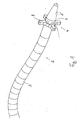
- the device 1 has a grease hose 2, which consists of a conventional hose body 3, a at the front end 4 thereof in this inserted outlet body 5 and an intermediate tube body 3 and outlet body 5 arranged guide star 6 consists.
- the outlet body 5 indicates immediately before the guide star 6 their periphery radially directed outlets 7, in particular in Shape of nozzles, on, through which the grease from the grease hose 2 can be pushed out.
- the guide star 6 has radially directed star ribs 8.
- the guide star 6 preferably sits freely rotatable between hose body 3 and nozzle body 5.
- the outlet body 5 has a subsequent to an outlet head 5a rear insertion lug 9 on, with to the outlets 7 rising trained annular ribs 10 provided is.
- To assemble the grease hose is first the star, the one the diameter of the annular ribs 10 superior Breakthrough 11 has the approach 9 and the Ribs 10 pushed to the outlet head 5a out. Subsequently is the hose body 3 via the neck 9 and the Rippen 10 pushed and by this force and form fit held on the outlet body 5 such that the star itself can turn.
- Fig. 3 shows the entire device according to the invention in a schematic representation.
- the device according to the invention 1 shows next to the fat tube shown here schematically 2 with the outlet body 5 a fat reservoir 21, a Pump 22 and a feed device 23 for the Hose body 3 on.
- FIGS. 4a and 4b show the use of the invention Device 1 in a power supply 30, which consists of a Protective tube 31 and passed through these lines 32 exists.
- the ready-made energy supply 30 in the form of a from the protective tube 31 and passed therethrough Lines 32 existing hose package is possible stretched and straightened or when greasing the already attached to a robot power supply the robot is placed in a position in which the hose package bent as little as possible, but rather runs as straight as possible.
- the outlet body 5 with the Star 6 is at one end of the guide tube 31 as possible placed in the middle of the pipes and the grease hose 2 with the outlet body 5 is then in a Protective tube 31 energy supply in the illustrated Embodiment inserted by the feed device 23.
- the feed device 23 can, as shown, two Rollers 32 which rotate in opposite directions and between the hose body 3 frictionally corresponding to their Advance the direction of rotation.
- the outlet body 5 is removed from the protective tube 31 taken out again.
- the Hose package on the protective tube 31 and lines 32 then a few times in several directions bent back and forth to the grease inside the protective tube 31 and around the lines 32 better to distribute.
- the protective tube package 31, 32 is attached to the robot, its parts be moved slowly relative to each other to this distribution effect to effect for the fat.
Landscapes
- Protection Of Pipes Against Damage, Friction, And Corrosion (AREA)
- Reciprocating Pumps (AREA)
- Guides For Winding Or Rewinding, Or Guides For Filamentary Materials (AREA)
- Loading And Unloading Of Fuel Tanks Or Ships (AREA)
Abstract
Description
- Fig. 1
- eine bevorzugte Ausführungsform des erfindungsgemäßen Fettschlauches mit Führungsstern und Auslasskörper;
- Fig. 2
- den Fettschlauch der Fig. 1 vor Zusammenbau;
- Fig. 3
- eine schematische Gesamtdarstellung der erfindungsgemäßen Vorrichtung zum Befetten;
- Fig. 4a
- eine schematische Darstellung der Durchführung des Fettschlauches durch einen Leitungen aufweisenden Führungsschlauch in Seitenansicht und
- Fig. 4b
- einen Querschnitt durch den Gegenstand der Fig. 4a.
- 1
- Vorrichtung
- 2
- Fettschlauch
- 3
- zwischenschlauchkörper
- 4
- Ende
- 5
- Auslasskörper
- 5a
- Auslasskopf
- 6
- Führungsstern
- 7
- Auslässe
- 8
- Stern-Rippen
- 9
- Einsteckansatz
- 10
- Rippen
- 11
- Öffnung
- 21
- Fettvorrat
- 22
- Pumpe
- 23
- Vorschubeinrichtung
- 30
- Energiezuführung
- 31
- Schutzschlauch
- 32
- Leitungen
Claims (20)
- Verfahren zum Befetten eines Schlauchpakets aus einem Schutzschlauch und durch diesen geführten Leitungen, insbesondere als Energiezuführung, dadurch gekennzeichnet, dass zumindest ein Fettschlauch über die gesamte Länge des Schutzschlauches zwischen den Leitungen bewegt wird und während der Bewegung durch mindestens einen Auslass das Fett aus dem Fettschlauch in den Schutzschlauch eingedrückt wird.
- Verfahren nach Anspruch 1, dadurch gekennzeichnet, dass das Fett nach Hindurchschieben des Fettschlauches durch den gesamten Schutzschlauch während des Zurückziehens des Fettschlauches durch den Schutzschlauch aus dem Fettschlauch ausgedrückt wird.
- Verfahren nach Anspruch 1 oder 2, dadurch gekennzeichnet, dass der Fettschlauch beim Hindurchbewegen durch den Schutzschlauch im wesentlichen in einer festen Radialposition relativ zu den Leitungen gehalten wird.
- Verfahren nach einem der Ansprüche 1 bis 3, dadurch gekennzeichnet, dass der Fettschlauch unter Zwischengreifen von Radialansätzen eines mit ihm verbundenen Sterns durch den Schutzschlauch bewegt wird.
- Verfahren nach Anspruch 4, dadurch gekennzeichnet, dass der Fettschlauch mit einem um ihn frei drehbaren Stern durch den Schutzschlauch bewegt wird.
- Verfahren nach einem der vorangehenden Ansprüche, dadurch gekennzeichnet, dass während des Hindurchbewegens des Fettschlauches durch den Schutzschlauch Fett durch radial gerichtete Auslässe aus dem Fettschlauch in den Schutzschlauch gedrückt wird.
- Verfahren nach einem der Ansprüche 1 bis 6, dadurch gekennzeichnet, dass der Fettschlauch automatisch durch den Schutzschlauch bewegt wird.
- Verfahren nach einem der vorangehenden Ansprüche, dadurch gekennzeichnet, dass der Fettschlauch mittels einer Vorschubeinrichtung durch den Schutzschlauch bewegt wird.
- Verfahren nach einem der vorangehenden Ansprüche, dadurch gekennzeichnet, dass der Fettschlauch manuell durch den Schutzschlauch bewegt wird.
- Verfahren nach einem der Ansprüche 1 bis 6, dadurch gekennzeichnet, dass das Fett aus dem Fettschlauch mittels eines Pumpvorganges herausgedrückt wird.
- Verfahren nach Anspruch 10, dadurch gekennzeichnet, dass das Fett manuell gepumpt wird.
- Verfahren nach Anspruch 10, dadurch gekennzeichnet, dass das Fett elektrisch gepumpt wird.
- Vorrichtung zum Befetten eines Schlauchpakets aus einem Schutzschlauch und durch diesen geführten Leitungen, insbesondere als Energiezuführung, gekennzeichnet durch mindestens einen mit mindestens einem Auslass (7) versehenen Fettschlauch (2).
- Vorrichtung nach Anspruch 13, dadurch gekennzeichnet, dass der Fettschlauch (2) mit einem Führungsstern (6) mit radialen Rippen versehen ist.
- Vorrichtung nach Anspruch 14, dadurch gekennzeichnet, dass der Führungsstern (6) zwischen einem Schlauchkörper (3) und einem Auslasskörper (5) angeordnet ist.
- Vorrichtung nach Anspruch 14 oder 15, dadurch gekennzeichnet, dass der Führungsstern (6) drehbar ist.
- Vorrichtung nach einem der Ansprüche 13 bis 16, dadurch gekennzeichnet, dass der Fettschlauch (2) einen Auslasskörper (5) mit radial gerichteten Auslässen (7) aufweist.
- Vorrichtung nach einem der Ansprüche 13 bis 17, gekennzeichnet durch eine Vorschubeinrichtung (23).
- Vorrichtung nach einem der Ansprüche 13 bis 18, gekennzeichnet durch eine Pumpeinrichtung (22).
- Vorrichtung nach einem der Ansprüche 13 bis 19, gekennzeichnet durch einen Fettvorrat (21).
Applications Claiming Priority (2)
| Application Number | Priority Date | Filing Date | Title |
|---|---|---|---|
| DE10340100 | 2003-08-30 | ||
| DE2003140100 DE10340100B4 (de) | 2003-08-30 | 2003-08-30 | Verfahren und Vorrichtung zum Befetten eines Schlauchpakets |
Publications (2)
| Publication Number | Publication Date |
|---|---|
| EP1511139A2 true EP1511139A2 (de) | 2005-03-02 |
| EP1511139A3 EP1511139A3 (de) | 2006-03-22 |
Family
ID=34089278
Family Applications (1)
| Application Number | Title | Priority Date | Filing Date |
|---|---|---|---|
| EP04020006A Withdrawn EP1511139A3 (de) | 2003-08-30 | 2004-08-24 | Verfahren und Vorrichtung zum Befetten eines Schlauchpakets |
Country Status (2)
| Country | Link |
|---|---|
| EP (1) | EP1511139A3 (de) |
| DE (1) | DE10340100B4 (de) |
Cited By (1)
| Publication number | Priority date | Publication date | Assignee | Title |
|---|---|---|---|---|
| WO2025186199A1 (de) * | 2024-03-07 | 2025-09-12 | Dürr Systems Ag | Schmiermittelschlauch, schlauchpaket, beschichtungsroboter und beschichtungsanlage |
Family Cites Families (3)
| Publication number | Priority date | Publication date | Assignee | Title |
|---|---|---|---|---|
| US3858687A (en) * | 1973-07-23 | 1975-01-07 | Allyn M Masarky | Method and apparatus for lubricating conductors being pulled through conduits |
| US4108279A (en) * | 1976-10-20 | 1978-08-22 | Thomas Industries Of Tennessee, Inc. | Dispenser and method for applying lubricant or other material to the interior of a conduit |
| US4324315A (en) * | 1979-05-15 | 1982-04-13 | Stone And Webster Eng. Cor. | Apparatus for lubricating electrical cable |
-
2003
- 2003-08-30 DE DE2003140100 patent/DE10340100B4/de not_active Expired - Fee Related
-
2004
- 2004-08-24 EP EP04020006A patent/EP1511139A3/de not_active Withdrawn
Cited By (1)
| Publication number | Priority date | Publication date | Assignee | Title |
|---|---|---|---|---|
| WO2025186199A1 (de) * | 2024-03-07 | 2025-09-12 | Dürr Systems Ag | Schmiermittelschlauch, schlauchpaket, beschichtungsroboter und beschichtungsanlage |
Also Published As
| Publication number | Publication date |
|---|---|
| EP1511139A3 (de) | 2006-03-22 |
| DE10340100B4 (de) | 2005-07-21 |
| DE10340100A1 (de) | 2005-04-14 |
Similar Documents
| Publication | Publication Date | Title |
|---|---|---|
| DE4205574C2 (de) | Kanalkörper und Verfahren zum Verlegen eines Kabels in diesem | |
| EP2248648B1 (de) | Verfahren und Vorrichtung zur Herstellung eines wärmeisolierten Leitungsrohrs | |
| DE69104934T2 (de) | Reinigungslanze zur Reinigung von Wärmetauscher-Rohrbündeln. | |
| DE1750240B2 (de) | Wanddurchführung zur Befestigung von mehreren parallelen Rohren, elektrischen Kabeln od.dgl | |
| DE102016109048A1 (de) | Aufnahmevorrichtung und Kabelbaum | |
| DE2418110B2 (de) | Bowdenzug | |
| DE102009056455A1 (de) | Leitungsschutzvorrichtung für einen Industrieroboter und Industrieroboter mit einer solchen Leitungsschutzvorrichtung | |
| DE2504882A1 (de) | Verfahren und vorrichtung zum aufbringen einer federnd dehnbaren spannhuelse | |
| DE19539236B4 (de) | Schlauch mit Fittings und Verfahren zu seiner Herstellung | |
| DE1900741C3 (de) | Vorrichtung zur Formgebung konischer Metallrohre | |
| DE3514316A1 (de) | Vorrichtung zum bearbeiten der oberflaeche eines metallrohres | |
| DE69709204T2 (de) | Rohrhaltervorrichtung | |
| DE102009043454B4 (de) | Rillschlauchspannvorrichtung | |
| DE10340100B4 (de) | Verfahren und Vorrichtung zum Befetten eines Schlauchpakets | |
| DE102015102897A1 (de) | Verfahren zum Zusammenbau einer Doppel-Wellrohranordnung, in der Kabel aufgenommen sind, und Vorrichtung zur Durchführung eines solchen Verfahrens | |
| DE2158816A1 (de) | Verbindungseinrichtung für die Kupplung von Leitungsabschnitten | |
| DE2631961C3 (de) | Verfahren zur Herstellung eines Flügelrads für einen hydraulischen Drehmomentenwandler | |
| DE2832763A1 (de) | Stuetzspirale fuer einen schlauch und schlauchanordnung mit stuetzspirale | |
| DE19851885C2 (de) | Halterung für einen Kabelstrang | |
| DE690138C (de) | Werkzeug zur Herstellung von Metallschlaeuchen aus glattwandigen Rohren durch schraubengangfoermige Rillung | |
| DE102016104562A1 (de) | Kugelgewindetrieb für eine hilfskraftunterstützte lenkung eines kraftfahrzeugs | |
| DE10357156B4 (de) | Rohrbiegeanlage | |
| EP0892472A1 (de) | Verfahren und Vorrichtung zum Verbinden eines aus Filamenten bestehenden Stranges mit einer Bohrung oder Hülse | |
| DE702133C (de) | Verfahren und Vorrichtung zur Herstellung von Leitungsseelen fuer Rohrdraehte und Bleimantelleitungen | |
| DE102016106669B4 (de) | Kanalinspektionseinheit mit bewegbar gelagertem Führungsstäbchen |
Legal Events
| Date | Code | Title | Description |
|---|---|---|---|
| PUAI | Public reference made under article 153(3) epc to a published international application that has entered the european phase |
Free format text: ORIGINAL CODE: 0009012 |
|
| AK | Designated contracting states |
Kind code of ref document: A2 Designated state(s): AT BE BG CH CY CZ DE DK EE ES FI FR GB GR HU IE IT LI LU MC NL PL PT RO SE SI SK TR |
|
| AX | Request for extension of the european patent |
Extension state: AL HR LT LV MK |
|
| PUAL | Search report despatched |
Free format text: ORIGINAL CODE: 0009013 |
|
| AK | Designated contracting states |
Kind code of ref document: A3 Designated state(s): AT BE BG CH CY CZ DE DK EE ES FI FR GB GR HU IE IT LI LU MC NL PL PT RO SE SI SK TR |
|
| AX | Request for extension of the european patent |
Extension state: AL HR LT LV MK |
|
| STAA | Information on the status of an ep patent application or granted ep patent |
Free format text: STATUS: THE APPLICATION HAS BEEN WITHDRAWN |
|
| 18W | Application withdrawn |
Effective date: 20060824 |
|
| P01 | Opt-out of the competence of the unified patent court (upc) registered |
Effective date: 20230528 |