EP1511126A1 - Kontaktelement und Verfahren zur Herstellung desselben - Google Patents
Kontaktelement und Verfahren zur Herstellung desselben Download PDFInfo
- Publication number
- EP1511126A1 EP1511126A1 EP03019176A EP03019176A EP1511126A1 EP 1511126 A1 EP1511126 A1 EP 1511126A1 EP 03019176 A EP03019176 A EP 03019176A EP 03019176 A EP03019176 A EP 03019176A EP 1511126 A1 EP1511126 A1 EP 1511126A1
- Authority
- EP
- European Patent Office
- Prior art keywords
- contact element
- holding
- contact
- section
- contact pin
- Prior art date
- Legal status (The legal status is an assumption and is not a legal conclusion. Google has not performed a legal analysis and makes no representation as to the accuracy of the status listed.)
- Granted
Links
Images

Classifications
-
- H—ELECTRICITY
- H01—ELECTRIC ELEMENTS
- H01R—ELECTRICALLY-CONDUCTIVE CONNECTIONS; STRUCTURAL ASSOCIATIONS OF A PLURALITY OF MUTUALLY-INSULATED ELECTRICAL CONNECTING ELEMENTS; COUPLING DEVICES; CURRENT COLLECTORS
- H01R13/00—Details of coupling devices of the kinds covered by groups H01R12/70 or H01R24/00 - H01R33/00
- H01R13/40—Securing contact members in or to a base or case; Insulating of contact members
- H01R13/42—Securing in a demountable manner
- H01R13/428—Securing in a demountable manner by resilient locking means on the contact members; by locking means on resilient contact members
- H01R13/432—Securing in a demountable manner by resilient locking means on the contact members; by locking means on resilient contact members by stamped-out resilient tongue snapping behind shoulder in base or case
-
- H—ELECTRICITY
- H01—ELECTRIC ELEMENTS
- H01R—ELECTRICALLY-CONDUCTIVE CONNECTIONS; STRUCTURAL ASSOCIATIONS OF A PLURALITY OF MUTUALLY-INSULATED ELECTRICAL CONNECTING ELEMENTS; COUPLING DEVICES; CURRENT COLLECTORS
- H01R13/00—Details of coupling devices of the kinds covered by groups H01R12/70 or H01R24/00 - H01R33/00
- H01R13/02—Contact members
- H01R13/04—Pins or blades for co-operation with sockets
-
- H—ELECTRICITY
- H01—ELECTRIC ELEMENTS
- H01R—ELECTRICALLY-CONDUCTIVE CONNECTIONS; STRUCTURAL ASSOCIATIONS OF A PLURALITY OF MUTUALLY-INSULATED ELECTRICAL CONNECTING ELEMENTS; COUPLING DEVICES; CURRENT COLLECTORS
- H01R43/00—Apparatus or processes specially adapted for manufacturing, assembling, maintaining, or repairing of line connectors or current collectors or for joining electric conductors
- H01R43/16—Apparatus or processes specially adapted for manufacturing, assembling, maintaining, or repairing of line connectors or current collectors or for joining electric conductors for manufacturing contact members, e.g. by punching and by bending
Definitions
- the present invention relates to a contact element and a method for the production of the same.
- Electrical leads can be electrically powered in various ways be connected to each other.
- One because of its simplicity and often The method used is to electrically connect the ends of each other to be connected lines with mutually complementary contact elements, for example, a contact element with a contact sleeve and a contact element with a contact pin to provide, and the nesting or pushing complementary contact elements together.
- the contact pins, the flat version also as contact tongues are often referred to either in equipment shots or Held connectors. They can especially in a production corresponding recordings are injection-molded by injection molding. For many applications, however, it is more advantageous to use the contact elements in corresponding contact element receptacles in such a housing a device receptacle or a connector to insert or to press.
- To contact elements with contact pins in the contact element recordings To position and hold, have the contact elements a fixing portion, by means of which the actual Contact pin is held in the contact element receptacle.
- the present invention is therefore based on the object, a contact element, in a contact element receptacle of a connector or a device receptacle is inserted, and a method for its To provide production.
- the contact element according to the invention for insertion into a contact element receiving a connector or a device receptacle includes a contact pin portion and an adjoining one Attachment section, the at least two each at different Side of the contact element arranged holding portions for holding the Contact element in the contact element receiving has, of which at least one laterally protrudes relative to the contact pin section, wherein the contact element is integrally formed as a sheet metal bent part.
- the object is further achieved by a method for the production a contact element for insertion into a contact element receptacle a connector or a device receptacle in which a punched Sheet metal part with a contact pin section and an adjoining Attachment portion having at least two holding portions, and at least one of the holding portions is bent so that it is opposite the contact pin section laterally protrudes that the holding sections each on different sides of the Contact element are arranged and that in particular by means of Holding portions of the contact element in the contact element receiving is durable.
- Inventive contact elements are with the invention Method to produce.
- the contact elements according to the invention are made of a single sheet metal part formed integrally as a sheet metal bent part, which is a particularly simple production results.
- the use of a Additional part avoided that at least a part of the fixing portion, in particular the holding sections, forms. This allows the manufacturing process be greatly simplified, since only a part to handle is.
- the contact pin section which when mated with a complementary Contact element, e.g. a contact sleeve, at least partially can be introduced into this, can be designed basically arbitrary and have different cross sections. In particular, he can also do the Form of a contact tongue, which has a flat cross-section transverse to a Plug-in direction in which the contact pin section with a complementary Contact element is plugged, accept. Furthermore, can the contact pin section to be elongated, wherein the longitudinal axis then simultaneously determines the plug-in direction in which the contact element can be plugged together with a complementary contact element is.
- the attachment section connects, depending on the training the contact pin section partially surrounded but this may not necessarily be the case.
- the Attachment portion has two holding portions, which at two different Pages of the contact element are arranged and by means of which held the contact element in the predetermined contact element recording can be.
- the attachment portion and in particular the holding portions can be designed in particular so that a one Cross-section orthogonal to a direction of insertion an enveloping curve in Essentially the cross section of a slot insertion of the contact element corresponds, in which the contact element is inserted.
- the holding portions are preferably formed flat to through an enlarged contact surface on walls of the contact element receiving to ensure a secure positioning of the contact element.
- the both holding sections can thereby directly or only together be connected via another portion of the attachment portion.
- At least one holding section is laterally, i. in particular laterally with respect to the plug-in direction or a longitudinal axis of the contact pin section, arranged projecting from the contact part, so that the Cross-section of the attachment section transversely to the direction of insertion in at least one direction is greater than the corresponding cross section of Pin section.
- the contact element is easy in einschiebbar a contact element recording, while still safe in this can be kept.
- the contact element according to the invention can furthermore be attached to the Attachment section subsequent or in this integrated connection section having, for connecting the contact element with a conductor is used and trained accordingly.
- the contact elements according to the invention are with the invention Method very easy to produce. It only needs appropriate punched sheet metal parts to be provided, in principle individually or by a band connected to each other the following Bending process can be supplied. These each have at least a contact pin portion and a fixing portion. there will also with each contact pin portion and attachment section corresponding section referred to after the preparation of the contact element the contact pin portion and the attachment portion of the finished contact element forms.
- the invention thus provides very easy to manufacture contact elements ready, which can be used in particular to provided for given contact element recordings, two-part contact elements to replace.
- At least one of Holding sections by a corresponding, at least once bent Section of a laterally at one in the contact section continuing center section of the mounting portion formed Flag is formed.
- a stamped sheet metal part a sheet metal part is, whose attachment portion is in the contact pin section continuing center section and one with the central section connected, with respect to a longitudinal axis of the contact pin portion having laterally projecting flag with a holding portion, and at the holding portion on the flag along a parallel to the longitudinal axis the contact pin section extending bending line at least is bent once.
- the middle section does not necessarily need this However, this is the shape of the contact pin section preferably the case.
- the lateral arrangement of the flag i. their arrangement transverse to the longitudinal direction of the contact pin section allows Low material use also a complex shape of the flag and thus possibly also the holding section, which then take on additional functions can.
- the holding portions to the contact pin portion and have mutually parallel outer surfaces. Under a course parallel to the contact pin section becomes a course parallel to the plug-in direction, in which this in a complementary contact element is insertable, or a longitudinal direction of the contact pin portion Roger that.
- the holding sections can then in particular abut respective walls of the contact element receiving and both forces and torques on the contact element recording transfer.
- the surfaces may be substantially, i. for example, except for breakthroughs or locking elements, even, i. Not arched, be.
- the edges of the Surfaces preferably also parallel to the contact pin section, i.e. its longitudinal direction.
- the holding sections essentially have one Rectangular shape on, leaving the area of the rectangle and two to each other parallel edges parallel to the contact pin portion, i. whose longitudinal or plug-in direction, run.
- the orthogonal to the contact pin section extending edges can then as a stop when inserted into a contact element receiving or for a second lock in the Serve contact element receptacle.
- the contact pin section an elongated, at least once U-shaped bent or folded section includes.
- at least the contact pin section along a parallel to a longitudinal axis of the contact pin section extending Bend line U-shaped in a first direction or bent folded up.
- the corresponding bending line can therefore in particular parallel to the later plugging direction.
- To the thickness of the formed by the contact pin portion contact pin to predetermined To be able to adapt requirements can, in addition to a corresponding Choice of the thickness of the sheet material of the contact pin section also several times be bent over.
- the central portion of the attachment portion bent or folded according to U-shape.
- the holding section on the flag in a second, the first direction opposite direction bent becomes.
- the holding portion can be bent back, so that it is substantially parallel to a corresponding surface of the Contact pin section runs.
- one of the two holding sections can be designed in such a way that that it continues continuously in the contact pin section.
- both holding portions relative to the contact pin portion protrude laterally.
- one of the holding sections by means of the other holding portion with the rest of the fixing portion and thus be connected to the contact pin section.
- both holding sections each by a corresponding, at least once bent portion respectively a laterally on a in the contact pin section continuing Center portion of the mounting portion formed formed flag is.
- a stamped sheet metal part with two on opposite sides used flags projecting from the central portion with holding portions and that the holding sections on the flags parallel to a longitudinal direction of the contact pin portion are bent.
- the contact element is thus produced in a particularly simple manner. Furthermore, preferred sheet metal layers of the central portion and the Holding portions rest on each other, so that a compact and very dimensionally stable mounting section results in the large forces between can transmit the contact element and the contact element recording.
- the holding sections a latching element, by means of which the contact element together with a complementary locking element in the contact element receiving is latched.
- the different or preferably may be the same.
- the locking element or the complementary locking element is formed be that there is an automatic initial locking of the contact element in the Contact element recording made possible by inserting the Contact element is reached in the contact element receptacle. By the Primary lock. in particular prevents the contact element pushed against the insertion direction of the contact element recording can be.
- the locking element in the holding section it may be on the one hand act a latching opening, which is very easy by punching in the Die-cut sheet metal part is produced before bending:
- the complementary Locking element can then by a corresponding projection or a resilient arm are formed in the contact element receptacle.
- the locking element is a resilient latching arm.
- This is also integrally formed as a portion of the bent sheet metal part.
- the complementary locking element of the contact element receiving can then by a corresponding projection or opening on or be formed in a wall of the contact element receptacle.
- the usage a resilient latching arm allows in particular a particularly simple design of the contact element receptacle, which is usually made of plastic is produced in an injection molding process, so that resilient Locking elements can be produced on this only with great effort. About that In addition, so is a simpler removal of the contact element from the contact element receiving by deflection of the latching arm enabled with a corresponding unlocking tool.
- the locking arm by a tongue the corresponding holding section is formed, which is bent back so that an end portion of the tongue through an opening in the holding portion engages and protrudes resiliently from the holding section.
- a punched Sheet metal part is a sheet metal part is used, in which at one of the holding sections one towards a free end of the contact pin portion projecting tongue is formed and the holding portion of the tongue has opposite opening, and that the tongue with its free End is bent so that the free end at least partially through the opening engages and resiliently projects laterally.
- the forming the latching arm Tongue is thus folded back to a certain extent and through the opening in guided the holding section, so that the free end protrudes from this.
- the movable part of the tongue i. their free end, can thus one have comparatively long length, so that at one for a locking necessary deflection of the latching arm of the elasticity of the Do not leave the metal alloy used to make the contact part becomes. Furthermore, the connection or articulation point in the Area between middle section and holding section moved so that with strong deflection of the locking arm an immediate force on this area and a possibly associated plastic Deformation can be avoided.
- This allows in particular the use of metals or metal alloys with a high electrical conductivity. In particular, so is a distance from Contact elements from the contact element recording without significant Damage allows when releasing the locking of the latching arms is depressed by a corresponding tool. The so distant Contact element can then be reused as a plastic Deformation of the latching arm and in particular the articulation area not took place.
- the holding portion with the latching arm another tongue has, whose free end is bent so that it at least partially on the side of the holding section from which the locking arm through the opening engages, is arranged in the area of the opening and a deflection of the Resting arms limited.
- a sheet metal part is used as the sheet metal part
- the holding section with the tongue has another tongue, and that their free End is bent in the area of the opening. This way you can the range of possible deflections of the latching arm safely in the elastic range being held.
- the other tongue is on the middle section and allows such a good power transmission between holding section and Midsection.
- the contact element according to the invention can thus at the same time very good electrical properties, i. a high electrical conductivity, and good mechanical properties, i. Dimensional stability of the holding sections and the contact pin portion and elasticity of the latching arms having.
- the contact element according to the invention may preferably consist of Sheet metal be made of a copper-Knet alloy.
- the contact element according to the invention can still have a connection portion for connection to a conductor.
- a connection portion for connection to a conductor preferably for a crimp connection corresponding Crimpable tabs for connection to a cable and / or crushable tabs for attaching a cable sheath be provided.
- the ends could also as insulation displacement terminals or be designed for the production of solder joints.
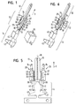
- Figs. 1 to 4 comprises an elongate contact element after a First preferred embodiment of the invention, a contact pin section 10, an adjoining mounting portion 12th and, subsequent to this, a connecting section 14 Contact element is made in one piece from a stamped sheet metal part 16 a copper-kneaded alloy shown in Fig. 5 is bent.
- the contact pin section 10 forms the actual contact pin of the Contact element and is for contacting with a complementary Contact element as a contact sleeve inserted into this.
- the contact section 10 is elongated with a longitudinal axis parallel to a direction of insertion S formed and U-shaped from a corresponding section 18 of the sheet metal part 16 bent or folded, so that through the added material thickness of the sheet metal part 16 the desired plug thickness of resulting contact pin is reached.
- the attachment portion 12 serves for mounting in a contact element receptacle 19 a connector with a linear slot 20 having a substantially rectangular cross section (see Fig. 1).
- the attachment portion 12 includes a middle portion 21, which in the contact pin section 10 passes and how this from a corresponding Section 22 of the sheet metal part 16 is bent or folded U-shaped.
- a middle portion 21 At the central portion 21 are on opposite sides of the Contact element substantially planar, parallel to flat sides the contact pin portion 10 and mutually oriented holding portions 24 arranged through corresponding, bent sections of formed laterally of the central portion 21 and the portion 22 Flags 26 are formed. This results in the contact pin section 10 and mutually parallel outer surfaces 27 of the holding elements 24th
- the holding sections 24 have a substantially rectangular Basic form, wherein orthogonal to the longitudinal axis of the contact pin portion 10 and the plug-in direction S extending front and rear edges 28 or 30 arise as a stop to limit the insertion in the contact element receiving 19 or as a stop for a secondary lock can serve in the contact element receptacle 19.
- the holding portions 24 are in a direction to this direction bent back and forth in the opposite direction, so that the Fixing portion 12 has a substantially M-shaped cross-section has (see Fig. 4).
- the envelope of the cross section of the attachment portion 12 transverse to the insertion direction S corresponds to the cross section of Insertion channel 20 of the contact element receiving 19th
- the holding portions 24 each have locking elements which pass through to the Holding portions 24 and the flags 26 against openings 32 in the Holding portions 24 formed, bent first tongues 34 formed are.
- the first tongues 34 are bent over so that they partially between the holding portions 24 and the contact pin portion 10th are arranged, wherein a free end of the first tabs 34 each as Locking arm 36 passes through the opening 32 and protrudes from this.
- the connection or articulation points of the latching arms 36 around which the Rastarm can be deflected, lies in each case between the Holding portions 24 and the central portion 21, -rarei the first tongues 34 in these areas on the central portion 21 rest (see Fig. 2D).
- first tongues 34 Opposite to the first tongues 34 are at the holding sections 24 each formed in the region of the trailing edges 30 second tongues 38, in the region between the holding portions 24 and the contact pin portion 10 are folded back, being partially in the area of Openings 32 are arranged and resting on the central portion 21 limit the deflection of the locking arms 36.
- the connecting portion 14 serves to connect the contact element with a cable and has Jardinquetschlaschen 40 and Jardinmantelquetschlaschen 42 for making a crimp connection with a lead on.
- the contact element can easily into a corresponding contact element receptacle 19 are inserted, wherein the resilient latching arms automatically in corresponding as latching openings in walls of the insertion channel 20 of the Kontäktelementam 19 trained complementary locking elements engage in the contact element receiving 19 and a first lock against withdrawal of the contact element from the contact element receiving 19 form opposite to the insertion direction.
- the contact element is made of an electrically conductive material, in the example made of a copper-kneading alloy, which has a limited resilience or has only a small elasticity range.
- the contact elements can very easily made of strip material made of sheet metal a copper-kneading alloy are produced, at the respective punched Sheet metal parts 16, as shown schematically in Fig. 5, arranged are. In the course of the production of the contact elements, these are from solved the tape.
- the sheet metal part 16 has an elongated portion 18 for forming the Contact pin section 10, an adjoining section 22 to form the middle section 21 with laterally arranged lugs 26 and subsequently a section 44 for forming the connecting portion 14 with the Jardinquetschlaschen 40 and Jardinmantelquetschlaschen 42 on.
- the flags 26 each have a rectangular basic shape and comprise corresponding holding portions 24 resulting sections 46 with rectangular Basic form. In the direction of the section 18 are respectively first Tongues 34 and formed on the opposite side second tongues 38. Furthermore, in the flags 26 each openings 32 in conjunction formed with the first and second tongues 34 and 38 so that the first tongues 34 are folded back through the openings 32 and the second tongues 38 by folding under the openings 32 in the area the free ends of the first tongues 34 can come to rest.
- first tongues 34 are first by the Openings 32 folded back so that their free ends from the openings 32 stand out as locking arms 36. Then the second Tongues 38 folded under the holding portions 24.
- Fig. 6 is schematically a contact element according to a second embodiment of the invention shown that from the contact element to the first embodiment only differs in that the first tongues 34 shorter and not through the openings 32nd are bent. Rather, the first tongues are based only on the middle section 21 off. All other parts are the same, so that these are designated the same reference numerals and for these the embodiments apply accordingly to the first embodiment.
- the openings 32 can now be used as locking elements for a complementary serve resilient latching elements of a contact element receiving.
- this contact element is with a previously described method corresponding method easy to produce, but training and bend the first tongues are changed accordingly.
Landscapes
- Engineering & Computer Science (AREA)
- Manufacturing & Machinery (AREA)
- Coupling Device And Connection With Printed Circuit (AREA)
- Manufacturing Of Electrical Connectors (AREA)
- Electroluminescent Light Sources (AREA)
- Optical Head (AREA)
Abstract
Description
- Fig. 1
- eine schematische perspektivische Darstellung eines Kontaktelements nach einer ersten bevorzugten Ausführungsform der Erfindung und eines Teils einer Kontaktelementaufnahme,
- Fig. 2A bis D
- Seitenansichten des Kontaktelements in Fig. 1 von vier verschiedenen Seiten,
- Fig. 3
- eine Rückansicht des Kontaktelements in Fig. 1 in einer Steckrichtung,
- Fig. 4
- eine Vorderansicht des Kontaktelements in Fig. 1 aus einer Richtung entgegen der Steckrichtung,
- Fig. 5
- eine schematische Draufsicht auf einen Abschnitt eines Bandmaterials mit einem ausgestanzten Blechteil zur Herstellung des Kontaktelements in Fig. 1, und
- Fig. 6
- eine perspektivische schematische Darstellung eines Kontaktelements nach einer zweiten bevorzugten Ausführungsform der Erfindung.
- 10
- Kontaktstiftabschnitt
- 12
- Befestigungsabschnitt
- 14
- Verbindungsabschnitt
- 16
- Blechteil
- 18
- Abschnitt
- 19
- Kontaktelementaufnahme
- 20
- Einschubkanal
- 21
- Mittelabschnitt
- 22
- Abschnitt
- 24
- Halteabschnitte
- 26
- Fahnen
- 27
- Oberflächen
- 28
- Vorderkanten
- 30
- Hinterkanten
- 32
- Öffnungen
- 34
- erste Zungen
- 36
- Rastarme
- 38
- zweite Zungen
- 40
- Kabelquetschlaschen
- 42
- Kabelmantelquetschlaschen
- 44
- Abschnitt
- 46
- Abschnitt
- 48
- Biegelinie
- 50, 50'
- Biegelinien
Claims (17)
- Kontaktelement zum Einschieben in eine Kontaktelementaufnahme (19) eines Steckverbinders oder einer Geräteaufnahme, mit
einem Kontaktstiftabschnitt (10), und
einem sich daran anschließenden Befestigungsabschnitt (12), der wenigstens zwei jeweils an verschiedenen Seiten des Kontaktelements angeordnete Halteabschnitte (24) zum Halten des Kontaktelements in der Kontaktelementaufnahme (19) aufweist, von denen wenigstens einer gegenüber dem Kontaktstiftabschnitt (10) seitlich absteht,
wobei das Kontaktelement einstückig als Blechbiegeteil ausgebildet ist. - Kontaktelement nach Anspruch 1,
dadurch gekennzeichnet, dass wenigstens einer der Halteabschnitte (24) durch einen entsprechenden, wenigstens einmal abgebogenen Abschnitt einer seitlich an einem sich in den Kontaktstiftabschnitt (10) fortsetzenden Mittelabschnitt (21) des Befestigungsabschnitts (12) ausgebildeten Fahne (26) gebildet ist. - Kontaktelement nach Anspruch 1 oder 2,
dadurch gekennzeichnet, dass die Halteabschnitte (24) zu dem Kontaktstiftabschnitt (10) und zueinander parallel verlaufende äußere Oberflächen (27) aufweisen. - Kontaktelement nach einem der vorhergehenden Ansprüche,
dadurch gekennzeichnet, dass beide Halteabschnitte (24) gegenüber dem Kontaktstiftabschnitt (10) seitlich abstehen. - Kontaktelement nach einem der vorhergehenden Ansprüche,
dadurch gekennzeichnet, dass der Kontaktstiftabschnitt (10) einen länglichen, wenigstens einmal U-förmig gebogenen oder gefalteten Abschnitt (18) umfasst. - Kontaktelement nach einem der vorhergehenden Ansprüche,
dadurch gekennzeichnet, dass wenigstens einer der Halteabschnitte (24) ein Rastelement (36) aufweist, mittels dessen das Kontaktelement zusammen mit einem komplementären Rastelement in der Kontaktelementaufnahme (19) verrastbar ist. - Kontaktelement nach Anspruch 6,
dadurch gekennzeichnet, dass das Rastelement ein federnder Rastarm (36) ist. - Kontaktelement nach Anspruch 7,
dadurch gekennzeichnet, dass der Rastarm (36) durch eine Zunge (34) an dem entsprechenden Halteabschnitt (24) gebildet ist, die so zurückgebogen ist, dass ein Endabschnitt der Zunge (34) durch eine Öffnung (32) in dem Halteabschnitt (24) greift und federnd von dem Halteabschnitt (24) absteht. - Kontaktelement nach Anspruch 8,
dadurch gekennzeichnet, dass sich ein an den federndem Endabschnitt (36) anschließender Abschnitt der Zunge (34) auf einem sich in den Kontaktstiftabschnitt (10) fortsetzenden Mittelabschnitt (21) des Befestigungsabschnitts (12) abstützt. - Kontaktelement nach Anspruch 8 oder 9,
dadurch gekennzeichnet, dass der Halteabschnitt (24) mit dem Rastarm (36) eine weitere Zunge (38) aufweist, deren freies Ende so umgebogen ist, dass es wenigstens teilweise auf der Seite des Halteabschnitts (24), von der der Rastarm (36) durch die Öffnung (32) greift, im Bereich der Öffnung (32) angeordnet ist und eine Auslenkung des Rastarms (36) begrenzt. - Verfahren zur Herstellung eines Kontaktelements zum Einschieben in eine Kontaktelementaufnahme (19) eines Steckverbinders oder
einer Geräteaufnahme,
bei dem ein gestanztes Blechteil (16) mit einem Kontaktstiftabschnitt (10) und einem sich daran anschließenden Befestigungsabschnitt (12), der wenigstens zwei Halteabschnitte (24) aufweist, bereitgestellt wird, und
bei dem wenigstens einer der Halteabschnitte (24) so abgebogen wird, dass er gegenüber dem Kontaktstiftabschnitt (10) seitlich absteht, dass die Halteabschnitte (24) jeweils an verschiedenen Seiten des Kontaktelements angeordnet sind und dass insbesondere mittels der Halteabschnitte (24) das Kontaktelement in der Kontaktelementaufnahme (19) haltbar ist. - Verfahren nach Anspruch 11,
dadurch gekennzeichnet, dass als gestanztes Blechteil ein Blechteil (16) verwendet wird, dessen Befestigungsabschnitt (12) einen sich in den Kontaktstiftabschnitt (10) fortsetzenden Mittelabschnitt (21) und eine mit dem Mittelabschnitt (21) verbundene, in Bezug auf eine Längsachse des Kontaktstiftabschnitts (10) seitlich abstehende Fahne (26) mit einem Halteabschnitt (24) aufweist, und
bei dem der Halteabschnitt (24) an der Fahne (26) entlang einer parallel zu der Längsachse des Kontaktstiftabschnitts (10) verlaufenden Biegelinie (50, 50') wenigstens einmal abgebogen wird. - Verfahren nach Anspruch 12,
dadurch gekennzeichnet, dass wenigstens der Kontaktstiftabschnitt (10) entlang einer parallel zu einer Längsachse des Kontaktstiftabschnitts (10) verlaufenden Biegelinie (48) U-förmig in einer ersten Richtung zusammengebogen oder zusammengefaltet wird. - Verfahren nach Anspruch 13,
dadurch gekennzeichnet, dass der Halteabschnitt (24) an der Fahne (26) in einer zweiten, der ersten Richtung entgegengesetzten Richtung abgebogen wird. - Verfahren nach Anspruch einem der Ansprüche 121 bis 14,
dadurch gekennzeichnet, dass ein gestanztes Blechteil (16) mit zwei an gegenüberliegenden Seiten von dem Mittelabschnitt (21) abstehenden Fahnen (26) mit Halteabschnitten (24) verwendet wird, und
dass die Halteabschnitte (24) an den Fahnen (26) parallel zu einer Längsrichtung (S) des Kontaktstiftabschnitts (10) abgebogen werden. - Verfahren nach einem der Ansprüche 11 bis 15,
dadurch gekennzeichnet, dass als gestanztes Blechteil ein Blechteil (16) verwendet wird, bei dem an einem der Halteabschnitte (24) eine in Richtung eines freien Endes des Kontaktstiftabschnitts (10) abstehende Zunge (34) ausgebildet ist und der Halteabschnitt (24) eine der Zunge (34) gegenüberliegende Öffnung (32) aufweist, und
dass die Zunge (34) mit ihrem freien Ende (36) so umgebogen wird, dass das freie Ende wenigstens teilweise durch die Öffnung (32) greift und federnd seitlich absteht. - Verfahren nach Anspruch 16,
dadurch gekennzeichnet, dass als Blechteil ein Blechteil (16) verwendet wird, dessen Halteabschnitt (24) mit der Zunge (34) eine weitere Zunge (38) aufweist, und
dass deren freies Ende in den Bereich der Öffnung (32) umgebogen wird.
Priority Applications (3)
| Application Number | Priority Date | Filing Date | Title |
|---|---|---|---|
| DE50308972T DE50308972D1 (de) | 2003-08-25 | 2003-08-25 | Kontaktelement und Verfahren zur Herstellung desselben |
| AT03019176T ATE383667T1 (de) | 2003-08-25 | 2003-08-25 | Kontaktelement und verfahren zur herstellung desselben |
| EP03019176A EP1511126B1 (de) | 2003-08-25 | 2003-08-25 | Kontaktelement und Verfahren zur Herstellung desselben |
Applications Claiming Priority (1)
| Application Number | Priority Date | Filing Date | Title |
|---|---|---|---|
| EP03019176A EP1511126B1 (de) | 2003-08-25 | 2003-08-25 | Kontaktelement und Verfahren zur Herstellung desselben |
Publications (2)
| Publication Number | Publication Date |
|---|---|
| EP1511126A1 true EP1511126A1 (de) | 2005-03-02 |
| EP1511126B1 EP1511126B1 (de) | 2008-01-09 |
Family
ID=34089600
Family Applications (1)
| Application Number | Title | Priority Date | Filing Date |
|---|---|---|---|
| EP03019176A Expired - Lifetime EP1511126B1 (de) | 2003-08-25 | 2003-08-25 | Kontaktelement und Verfahren zur Herstellung desselben |
Country Status (3)
| Country | Link |
|---|---|
| EP (1) | EP1511126B1 (de) |
| AT (1) | ATE383667T1 (de) |
| DE (1) | DE50308972D1 (de) |
Families Citing this family (1)
| Publication number | Priority date | Publication date | Assignee | Title |
|---|---|---|---|---|
| WO2026073799A1 (de) * | 2024-10-02 | 2026-04-09 | Hirschmann Automotive Gmbh | Einteiliger mittels eines faltvorgangs hergestellter kontakt für einen steckverbinder |
Citations (2)
| Publication number | Priority date | Publication date | Assignee | Title |
|---|---|---|---|---|
| EP0552741A2 (de) * | 1992-01-22 | 1993-07-28 | The Whitaker Corporation | Elektrischer Kontakt sowie Material und Herstellungsverfahren |
| US5445541A (en) * | 1992-01-04 | 1995-08-29 | Framatome Connectors International | Blade contact for electric plugs |
-
2003
- 2003-08-25 AT AT03019176T patent/ATE383667T1/de not_active IP Right Cessation
- 2003-08-25 EP EP03019176A patent/EP1511126B1/de not_active Expired - Lifetime
- 2003-08-25 DE DE50308972T patent/DE50308972D1/de not_active Expired - Lifetime
Patent Citations (2)
| Publication number | Priority date | Publication date | Assignee | Title |
|---|---|---|---|---|
| US5445541A (en) * | 1992-01-04 | 1995-08-29 | Framatome Connectors International | Blade contact for electric plugs |
| EP0552741A2 (de) * | 1992-01-22 | 1993-07-28 | The Whitaker Corporation | Elektrischer Kontakt sowie Material und Herstellungsverfahren |
Also Published As
| Publication number | Publication date |
|---|---|
| ATE383667T1 (de) | 2008-01-15 |
| EP1511126B1 (de) | 2008-01-09 |
| DE50308972D1 (de) | 2008-02-21 |
Similar Documents
| Publication | Publication Date | Title |
|---|---|---|
| EP2843764B1 (de) | Federkraftklemme für Leiter | |
| DE69311442T2 (de) | Kontaktanordnung | |
| DE2414640C3 (de) | Elektrischer Verbinder mit einer metallischen Anschlußklemme | |
| DE102014011523B4 (de) | Elektrische anschlussanordnung | |
| EP4066320A1 (de) | Federkraftklemme für leiter | |
| DE69426133T2 (de) | Elektrische Kontaktstruktur mit geringer Einsteckkraft | |
| DE8713038U1 (de) | Buchsenartiger elektrischer Anschluß | |
| DE69403428T2 (de) | Elektrischer Verbinder und Anschlusselement dafür zur Verbindung mit ein Messerkontakt | |
| EP3375048B1 (de) | Steckkontakt | |
| EP1429423B1 (de) | Elektrische Steckverbindung mit einem Gehäuse und einem Hochstromkontakt | |
| DE102013106117B4 (de) | Steckverbinderanordnung und Steckverbindungssystem | |
| DE69221428T2 (de) | Elektrische Kontaktbuchse | |
| DE112021004984T5 (de) | Lötfreies Draht-zu-Platine einpaariges Ethernet-Steckverbindungssystem | |
| DE4016114C2 (de) | Elektrischer Mehrkontakt-Verbinder, der eine geringe Verbindungs- und Trennkraft erfordert | |
| DE102009006828A1 (de) | Schneidklemmkontakt mit Entkopplungsstelle und Kontaktanordnung mit Schneidklemmkontakt | |
| WO2021004893A1 (de) | Direktsteckverbinder | |
| DE69310439T2 (de) | Verriegelbarer elektrischer Verbinderanordnung | |
| DE69300241T2 (de) | Elektrische Anschlussklemme. | |
| DE2119060B2 (de) | Steckverbindung | |
| EP1511126B1 (de) | Kontaktelement und Verfahren zur Herstellung desselben | |
| DE102022125629A1 (de) | Elektrische Verbindungsvorrichtung | |
| DE69823759T2 (de) | Haltevorrichtung zum Montieren elektrischer Verbinder | |
| EP1720222B1 (de) | Steckverbinder, insbesondere für Airbag-Zündsysteme | |
| DE69211516T2 (de) | Elektrische Anschlussanordnung mit Anschlussverriegelungselement | |
| DE4437791C1 (de) | Kabelsteckverbinder |
Legal Events
| Date | Code | Title | Description |
|---|---|---|---|
| PUAI | Public reference made under article 153(3) epc to a published international application that has entered the european phase |
Free format text: ORIGINAL CODE: 0009012 |
|
| 17P | Request for examination filed |
Effective date: 20040805 |
|
| AK | Designated contracting states |
Kind code of ref document: A1 Designated state(s): AT BE BG CH CY CZ DE DK EE ES FI FR GB GR HU IE IT LI LU MC NL PT RO SE SI SK TR |
|
| AX | Request for extension of the european patent |
Extension state: AL LT LV MK |
|
| AKX | Designation fees paid |
Designated state(s): AT BE BG CH CY CZ DE DK EE ES FI FR GB GR HU IE IT LI LU MC NL PT RO SE SI SK TR |
|
| GRAP | Despatch of communication of intention to grant a patent |
Free format text: ORIGINAL CODE: EPIDOSNIGR1 |
|
| RIC1 | Information provided on ipc code assigned before grant |
Ipc: H01R 13/432 20060101ALI20070705BHEP Ipc: H01R 13/04 20060101AFI20070705BHEP Ipc: H01R 43/16 20060101ALI20070705BHEP |
|
| GRAS | Grant fee paid |
Free format text: ORIGINAL CODE: EPIDOSNIGR3 |
|
| GRAA | (expected) grant |
Free format text: ORIGINAL CODE: 0009210 |
|
| AK | Designated contracting states |
Kind code of ref document: B1 Designated state(s): AT BE BG CH CY CZ DE DK EE ES FI FR GB GR HU IE IT LI LU MC NL PT RO SE SI SK TR |
|
| REG | Reference to a national code |
Ref country code: GB Ref legal event code: FG4D Free format text: NOT ENGLISH |
|
| REG | Reference to a national code |
Ref country code: CH Ref legal event code: EP |
|
| REG | Reference to a national code |
Ref country code: IE Ref legal event code: FG4D Free format text: LANGUAGE OF EP DOCUMENT: GERMAN |
|
| REF | Corresponds to: |
Ref document number: 50308972 Country of ref document: DE Date of ref document: 20080221 Kind code of ref document: P |
|
| PG25 | Lapsed in a contracting state [announced via postgrant information from national office to epo] |
Ref country code: NL Free format text: LAPSE BECAUSE OF FAILURE TO SUBMIT A TRANSLATION OF THE DESCRIPTION OR TO PAY THE FEE WITHIN THE PRESCRIBED TIME-LIMIT Effective date: 20080109 Ref country code: SI Free format text: LAPSE BECAUSE OF FAILURE TO SUBMIT A TRANSLATION OF THE DESCRIPTION OR TO PAY THE FEE WITHIN THE PRESCRIBED TIME-LIMIT Effective date: 20080109 |
|
| NLV1 | Nl: lapsed or annulled due to failure to fulfill the requirements of art. 29p and 29m of the patents act | ||
| ET | Fr: translation filed | ||
| PG25 | Lapsed in a contracting state [announced via postgrant information from national office to epo] |
Ref country code: FI Free format text: LAPSE BECAUSE OF FAILURE TO SUBMIT A TRANSLATION OF THE DESCRIPTION OR TO PAY THE FEE WITHIN THE PRESCRIBED TIME-LIMIT Effective date: 20080109 Ref country code: ES Free format text: LAPSE BECAUSE OF FAILURE TO SUBMIT A TRANSLATION OF THE DESCRIPTION OR TO PAY THE FEE WITHIN THE PRESCRIBED TIME-LIMIT Effective date: 20080420 |
|
| GBV | Gb: ep patent (uk) treated as always having been void in accordance with gb section 77(7)/1977 [no translation filed] | ||
| PG25 | Lapsed in a contracting state [announced via postgrant information from national office to epo] |
Ref country code: BG Free format text: LAPSE BECAUSE OF FAILURE TO SUBMIT A TRANSLATION OF THE DESCRIPTION OR TO PAY THE FEE WITHIN THE PRESCRIBED TIME-LIMIT Effective date: 20080409 |
|
| PG25 | Lapsed in a contracting state [announced via postgrant information from national office to epo] |
Ref country code: PT Free format text: LAPSE BECAUSE OF FAILURE TO SUBMIT A TRANSLATION OF THE DESCRIPTION OR TO PAY THE FEE WITHIN THE PRESCRIBED TIME-LIMIT Effective date: 20080609 |
|
| REG | Reference to a national code |
Ref country code: IE Ref legal event code: FD4D |
|
| PG25 | Lapsed in a contracting state [announced via postgrant information from national office to epo] |
Ref country code: SE Free format text: LAPSE BECAUSE OF FAILURE TO SUBMIT A TRANSLATION OF THE DESCRIPTION OR TO PAY THE FEE WITHIN THE PRESCRIBED TIME-LIMIT Effective date: 20080409 Ref country code: IE Free format text: LAPSE BECAUSE OF FAILURE TO SUBMIT A TRANSLATION OF THE DESCRIPTION OR TO PAY THE FEE WITHIN THE PRESCRIBED TIME-LIMIT Effective date: 20080109 Ref country code: SK Free format text: LAPSE BECAUSE OF FAILURE TO SUBMIT A TRANSLATION OF THE DESCRIPTION OR TO PAY THE FEE WITHIN THE PRESCRIBED TIME-LIMIT Effective date: 20080109 Ref country code: DK Free format text: LAPSE BECAUSE OF FAILURE TO SUBMIT A TRANSLATION OF THE DESCRIPTION OR TO PAY THE FEE WITHIN THE PRESCRIBED TIME-LIMIT Effective date: 20080109 Ref country code: CZ Free format text: LAPSE BECAUSE OF FAILURE TO SUBMIT A TRANSLATION OF THE DESCRIPTION OR TO PAY THE FEE WITHIN THE PRESCRIBED TIME-LIMIT Effective date: 20080109 |
|
| PLBE | No opposition filed within time limit |
Free format text: ORIGINAL CODE: 0009261 |
|
| STAA | Information on the status of an ep patent application or granted ep patent |
Free format text: STATUS: NO OPPOSITION FILED WITHIN TIME LIMIT |
|
| PG25 | Lapsed in a contracting state [announced via postgrant information from national office to epo] |
Ref country code: RO Free format text: LAPSE BECAUSE OF FAILURE TO SUBMIT A TRANSLATION OF THE DESCRIPTION OR TO PAY THE FEE WITHIN THE PRESCRIBED TIME-LIMIT Effective date: 20080109 |
|
| 26N | No opposition filed |
Effective date: 20081010 |
|
| PG25 | Lapsed in a contracting state [announced via postgrant information from national office to epo] |
Ref country code: GB Free format text: LAPSE BECAUSE OF FAILURE TO SUBMIT A TRANSLATION OF THE DESCRIPTION OR TO PAY THE FEE WITHIN THE PRESCRIBED TIME-LIMIT Effective date: 20080109 |
|
| PG25 | Lapsed in a contracting state [announced via postgrant information from national office to epo] |
Ref country code: MC Free format text: LAPSE BECAUSE OF NON-PAYMENT OF DUE FEES Effective date: 20080831 |
|
| REG | Reference to a national code |
Ref country code: CH Ref legal event code: PL |
|
| PG25 | Lapsed in a contracting state [announced via postgrant information from national office to epo] |
Ref country code: EE Free format text: LAPSE BECAUSE OF FAILURE TO SUBMIT A TRANSLATION OF THE DESCRIPTION OR TO PAY THE FEE WITHIN THE PRESCRIBED TIME-LIMIT Effective date: 20080109 |
|
| PG25 | Lapsed in a contracting state [announced via postgrant information from national office to epo] |
Ref country code: CH Free format text: LAPSE BECAUSE OF NON-PAYMENT OF DUE FEES Effective date: 20080831 Ref country code: LI Free format text: LAPSE BECAUSE OF NON-PAYMENT OF DUE FEES Effective date: 20080831 |
|
| PG25 | Lapsed in a contracting state [announced via postgrant information from national office to epo] |
Ref country code: BE Free format text: LAPSE BECAUSE OF NON-PAYMENT OF DUE FEES Effective date: 20080831 Ref country code: CY Free format text: LAPSE BECAUSE OF FAILURE TO SUBMIT A TRANSLATION OF THE DESCRIPTION OR TO PAY THE FEE WITHIN THE PRESCRIBED TIME-LIMIT Effective date: 20080109 |
|
| PG25 | Lapsed in a contracting state [announced via postgrant information from national office to epo] |
Ref country code: AT Free format text: LAPSE BECAUSE OF NON-PAYMENT OF DUE FEES Effective date: 20080825 |
|
| PG25 | Lapsed in a contracting state [announced via postgrant information from national office to epo] |
Ref country code: LU Free format text: LAPSE BECAUSE OF NON-PAYMENT OF DUE FEES Effective date: 20080825 Ref country code: HU Free format text: LAPSE BECAUSE OF FAILURE TO SUBMIT A TRANSLATION OF THE DESCRIPTION OR TO PAY THE FEE WITHIN THE PRESCRIBED TIME-LIMIT Effective date: 20080710 |
|
| PG25 | Lapsed in a contracting state [announced via postgrant information from national office to epo] |
Ref country code: TR Free format text: LAPSE BECAUSE OF FAILURE TO SUBMIT A TRANSLATION OF THE DESCRIPTION OR TO PAY THE FEE WITHIN THE PRESCRIBED TIME-LIMIT Effective date: 20080109 |
|
| PG25 | Lapsed in a contracting state [announced via postgrant information from national office to epo] |
Ref country code: GR Free format text: LAPSE BECAUSE OF FAILURE TO SUBMIT A TRANSLATION OF THE DESCRIPTION OR TO PAY THE FEE WITHIN THE PRESCRIBED TIME-LIMIT Effective date: 20080410 |
|
| REG | Reference to a national code |
Ref country code: FR Ref legal event code: PLFP Year of fee payment: 14 |
|
| REG | Reference to a national code |
Ref country code: FR Ref legal event code: PLFP Year of fee payment: 15 |
|
| REG | Reference to a national code |
Ref country code: FR Ref legal event code: PLFP Year of fee payment: 16 |
|
| REG | Reference to a national code |
Ref country code: DE Ref legal event code: R082 Ref document number: 50308972 Country of ref document: DE Representative=s name: MANITZ FINSTERWALD PATENT- UND RECHTSANWALTSPA, DE Ref country code: DE Ref legal event code: R082 Ref document number: 50308972 Country of ref document: DE Representative=s name: MANITZ FINSTERWALD PATENTANWAELTE PARTMBB, DE Ref country code: DE Ref legal event code: R081 Ref document number: 50308972 Country of ref document: DE Owner name: APTIV TECHNOLOGIES LIMITED, BB Free format text: FORMER OWNER: DELPHI TECHNOLOGIES, INC., TROY, MICH., US |
|
| PGFP | Annual fee paid to national office [announced via postgrant information from national office to epo] |
Ref country code: IT Payment date: 20210730 Year of fee payment: 19 |
|
| PGFP | Annual fee paid to national office [announced via postgrant information from national office to epo] |
Ref country code: DE Payment date: 20220615 Year of fee payment: 20 |
|
| PGFP | Annual fee paid to national office [announced via postgrant information from national office to epo] |
Ref country code: FR Payment date: 20220825 Year of fee payment: 20 |
|
| P01 | Opt-out of the competence of the unified patent court (upc) registered |
Effective date: 20230425 |
|
| PG25 | Lapsed in a contracting state [announced via postgrant information from national office to epo] |
Ref country code: IT Free format text: LAPSE BECAUSE OF NON-PAYMENT OF DUE FEES Effective date: 20220825 |
|
| REG | Reference to a national code |
Ref country code: DE Ref legal event code: R071 Ref document number: 50308972 Country of ref document: DE |