EP1511094B1 - Light emitting device and method of fabrication - Google Patents
Light emitting device and method of fabrication Download PDFInfo
- Publication number
- EP1511094B1 EP1511094B1 EP04018867.4A EP04018867A EP1511094B1 EP 1511094 B1 EP1511094 B1 EP 1511094B1 EP 04018867 A EP04018867 A EP 04018867A EP 1511094 B1 EP1511094 B1 EP 1511094B1
- Authority
- EP
- European Patent Office
- Prior art keywords
- layer
- light
- emitting component
- component according
- layers
- Prior art date
- Legal status (The legal status is an assumption and is not a legal conclusion. Google has not performed a legal analysis and makes no representation as to the accuracy of the status listed.)
- Expired - Lifetime
Links
- 238000004519 manufacturing process Methods 0.000 title claims description 5
- 239000010410 layer Substances 0.000 claims description 153
- 229920000642 polymer Polymers 0.000 claims description 37
- 238000000034 method Methods 0.000 claims description 23
- 239000002052 molecular layer Substances 0.000 claims description 23
- 239000000463 material Substances 0.000 claims description 19
- 239000002019 doping agent Substances 0.000 claims description 18
- 239000000758 substrate Substances 0.000 claims description 13
- 239000012044 organic layer Substances 0.000 claims description 9
- 239000011159 matrix material Substances 0.000 claims description 8
- 150000003384 small molecules Chemical class 0.000 claims description 7
- 238000009792 diffusion process Methods 0.000 claims description 2
- FVKFHMNJTHKMRX-UHFFFAOYSA-N 3,4,6,7,8,9-hexahydro-2H-pyrimido[1,2-a]pyrimidine Chemical compound C1CCN2CCCNC2=N1 FVKFHMNJTHKMRX-UHFFFAOYSA-N 0.000 claims 2
- 238000007641 inkjet printing Methods 0.000 claims 2
- 239000000126 substance Substances 0.000 claims 2
- 238000009834 vaporization Methods 0.000 claims 1
- 238000002347 injection Methods 0.000 description 18
- 239000007924 injection Substances 0.000 description 18
- 230000008569 process Effects 0.000 description 14
- 230000005525 hole transport Effects 0.000 description 12
- 229920001467 poly(styrenesulfonates) Polymers 0.000 description 6
- RICKKZXCGCSLIU-UHFFFAOYSA-N 2-[2-[carboxymethyl-[[3-hydroxy-5-(hydroxymethyl)-2-methylpyridin-4-yl]methyl]amino]ethyl-[[3-hydroxy-5-(hydroxymethyl)-2-methylpyridin-4-yl]methyl]amino]acetic acid Chemical compound CC1=NC=C(CO)C(CN(CCN(CC(O)=O)CC=2C(=C(C)N=CC=2CO)O)CC(O)=O)=C1O RICKKZXCGCSLIU-UHFFFAOYSA-N 0.000 description 5
- 239000002800 charge carrier Substances 0.000 description 5
- 230000008020 evaporation Effects 0.000 description 5
- 238000001704 evaporation Methods 0.000 description 5
- OYPRJOBELJOOCE-UHFFFAOYSA-N Calcium Chemical compound [Ca] OYPRJOBELJOOCE-UHFFFAOYSA-N 0.000 description 4
- 229920000144 PEDOT:PSS Polymers 0.000 description 4
- 229920001609 Poly(3,4-ethylenedioxythiophene) Polymers 0.000 description 4
- 229910052788 barium Inorganic materials 0.000 description 4
- DSAJWYNOEDNPEQ-UHFFFAOYSA-N barium atom Chemical compound [Ba] DSAJWYNOEDNPEQ-UHFFFAOYSA-N 0.000 description 4
- 229910052791 calcium Inorganic materials 0.000 description 4
- 239000011575 calcium Substances 0.000 description 4
- 229920000767 polyaniline Polymers 0.000 description 4
- 229910052782 aluminium Inorganic materials 0.000 description 3
- XAGFODPZIPBFFR-UHFFFAOYSA-N aluminium Chemical compound [Al] XAGFODPZIPBFFR-UHFFFAOYSA-N 0.000 description 3
- 230000004888 barrier function Effects 0.000 description 3
- 238000010276 construction Methods 0.000 description 3
- 238000004770 highest occupied molecular orbital Methods 0.000 description 3
- 239000011229 interlayer Substances 0.000 description 3
- 238000004768 lowest unoccupied molecular orbital Methods 0.000 description 3
- 239000002904 solvent Substances 0.000 description 3
- 238000004544 sputter deposition Methods 0.000 description 3
- 239000000370 acceptor Substances 0.000 description 2
- 229910052792 caesium Inorganic materials 0.000 description 2
- TVFDJXOCXUVLDH-UHFFFAOYSA-N caesium atom Chemical compound [Cs] TVFDJXOCXUVLDH-UHFFFAOYSA-N 0.000 description 2
- 238000000354 decomposition reaction Methods 0.000 description 2
- 229910052751 metal Inorganic materials 0.000 description 2
- 239000002184 metal Substances 0.000 description 2
- DCZNSJVFOQPSRV-UHFFFAOYSA-N n,n-diphenyl-4-[4-(n-phenylanilino)phenyl]aniline Chemical compound C1=CC=CC=C1N(C=1C=CC(=CC=1)C=1C=CC(=CC=1)N(C=1C=CC=CC=1)C=1C=CC=CC=1)C1=CC=CC=C1 DCZNSJVFOQPSRV-UHFFFAOYSA-N 0.000 description 2
- 239000011368 organic material Substances 0.000 description 2
- 239000013047 polymeric layer Substances 0.000 description 2
- 229960002796 polystyrene sulfonate Drugs 0.000 description 2
- 239000011970 polystyrene sulfonate Substances 0.000 description 2
- CXZRDVVUVDYSCQ-UHFFFAOYSA-M pyronin B Chemical compound [Cl-].C1=CC(=[N+](CC)CC)C=C2OC3=CC(N(CC)CC)=CC=C3C=C21 CXZRDVVUVDYSCQ-UHFFFAOYSA-M 0.000 description 2
- 238000005215 recombination Methods 0.000 description 2
- 230000006798 recombination Effects 0.000 description 2
- WFKWXMTUELFFGS-UHFFFAOYSA-N tungsten Chemical compound [W] WFKWXMTUELFFGS-UHFFFAOYSA-N 0.000 description 2
- 229910052721 tungsten Inorganic materials 0.000 description 2
- 239000010937 tungsten Substances 0.000 description 2
- XLYOFNOQVPJJNP-UHFFFAOYSA-N water Substances O XLYOFNOQVPJJNP-UHFFFAOYSA-N 0.000 description 2
- IXHWGNYCZPISET-UHFFFAOYSA-N 2-[4-(dicyanomethylidene)-2,3,5,6-tetrafluorocyclohexa-2,5-dien-1-ylidene]propanedinitrile Chemical compound FC1=C(F)C(=C(C#N)C#N)C(F)=C(F)C1=C(C#N)C#N IXHWGNYCZPISET-UHFFFAOYSA-N 0.000 description 1
- UPSWHSOSMRAWEH-UHFFFAOYSA-N 2-n,3-n,4-n-tris(3-methylphenyl)-1-n,1-n,2-n,3-n,4-n-pentakis-phenylbenzene-1,2,3,4-tetramine Chemical compound CC1=CC=CC(N(C=2C=CC=CC=2)C=2C(=C(N(C=3C=CC=CC=3)C=3C=C(C)C=CC=3)C(N(C=3C=CC=CC=3)C=3C=CC=CC=3)=CC=2)N(C=2C=CC=CC=2)C=2C=C(C)C=CC=2)=C1 UPSWHSOSMRAWEH-UHFFFAOYSA-N 0.000 description 1
- DIVZFUBWFAOMCW-UHFFFAOYSA-N 4-n-(3-methylphenyl)-1-n,1-n-bis[4-(n-(3-methylphenyl)anilino)phenyl]-4-n-phenylbenzene-1,4-diamine Chemical compound CC1=CC=CC(N(C=2C=CC=CC=2)C=2C=CC(=CC=2)N(C=2C=CC(=CC=2)N(C=2C=CC=CC=2)C=2C=C(C)C=CC=2)C=2C=CC(=CC=2)N(C=2C=CC=CC=2)C=2C=C(C)C=CC=2)=C1 DIVZFUBWFAOMCW-UHFFFAOYSA-N 0.000 description 1
- QURLTYPDDOGVKH-UHFFFAOYSA-N C(CN1)CN2C1NCCC2 Chemical compound C(CN1)CN2C1NCCC2 QURLTYPDDOGVKH-UHFFFAOYSA-N 0.000 description 1
- ATJFFYVFTNAWJD-UHFFFAOYSA-N Tin Chemical compound [Sn] ATJFFYVFTNAWJD-UHFFFAOYSA-N 0.000 description 1
- 150000001450 anions Chemical class 0.000 description 1
- QVGXLLKOCUKJST-UHFFFAOYSA-N atomic oxygen Chemical compound [O] QVGXLLKOCUKJST-UHFFFAOYSA-N 0.000 description 1
- 230000015572 biosynthetic process Effects 0.000 description 1
- FJDQFPXHSGXQBY-UHFFFAOYSA-L caesium carbonate Chemical compound [Cs+].[Cs+].[O-]C([O-])=O FJDQFPXHSGXQBY-UHFFFAOYSA-L 0.000 description 1
- 229910000024 caesium carbonate Inorganic materials 0.000 description 1
- 230000008859 change Effects 0.000 description 1
- 239000003086 colorant Substances 0.000 description 1
- 239000002131 composite material Substances 0.000 description 1
- 150000001875 compounds Chemical class 0.000 description 1
- 230000001419 dependent effect Effects 0.000 description 1
- 238000010894 electron beam technology Methods 0.000 description 1
- 239000007789 gas Substances 0.000 description 1
- 239000011521 glass Substances 0.000 description 1
- PCHJSUWPFVWCPO-UHFFFAOYSA-N gold Chemical compound [Au] PCHJSUWPFVWCPO-UHFFFAOYSA-N 0.000 description 1
- 229910052737 gold Inorganic materials 0.000 description 1
- 239000010931 gold Substances 0.000 description 1
- 230000006872 improvement Effects 0.000 description 1
- 229910052738 indium Inorganic materials 0.000 description 1
- APFVFJFRJDLVQX-UHFFFAOYSA-N indium atom Chemical compound [In] APFVFJFRJDLVQX-UHFFFAOYSA-N 0.000 description 1
- AMGQUBHHOARCQH-UHFFFAOYSA-N indium;oxotin Chemical compound [In].[Sn]=O AMGQUBHHOARCQH-UHFFFAOYSA-N 0.000 description 1
- 230000010354 integration Effects 0.000 description 1
- 239000006193 liquid solution Substances 0.000 description 1
- 230000004048 modification Effects 0.000 description 1
- 238000012986 modification Methods 0.000 description 1
- 238000005457 optimization Methods 0.000 description 1
- 239000001301 oxygen Substances 0.000 description 1
- 229910052760 oxygen Inorganic materials 0.000 description 1
- 239000002243 precursor Substances 0.000 description 1
- 238000002360 preparation method Methods 0.000 description 1
- 239000002356 single layer Substances 0.000 description 1
- 239000000243 solution Substances 0.000 description 1
- 239000010409 thin film Substances 0.000 description 1
- 229910052718 tin Inorganic materials 0.000 description 1
Images
Classifications
-
- H—ELECTRICITY
- H10—SEMICONDUCTOR DEVICES; ELECTRIC SOLID-STATE DEVICES NOT OTHERWISE PROVIDED FOR
- H10K—ORGANIC ELECTRIC SOLID-STATE DEVICES
- H10K50/00—Organic light-emitting devices
- H10K50/10—OLEDs or polymer light-emitting diodes [PLED]
- H10K50/14—Carrier transporting layers
-
- H—ELECTRICITY
- H10—SEMICONDUCTOR DEVICES; ELECTRIC SOLID-STATE DEVICES NOT OTHERWISE PROVIDED FOR
- H10K—ORGANIC ELECTRIC SOLID-STATE DEVICES
- H10K50/00—Organic light-emitting devices
- H10K50/10—OLEDs or polymer light-emitting diodes [PLED]
- H10K50/11—OLEDs or polymer light-emitting diodes [PLED] characterised by the electroluminescent [EL] layers
-
- H—ELECTRICITY
- H10—SEMICONDUCTOR DEVICES; ELECTRIC SOLID-STATE DEVICES NOT OTHERWISE PROVIDED FOR
- H10K—ORGANIC ELECTRIC SOLID-STATE DEVICES
- H10K50/00—Organic light-emitting devices
- H10K50/10—OLEDs or polymer light-emitting diodes [PLED]
- H10K50/14—Carrier transporting layers
- H10K50/15—Hole transporting layers
- H10K50/155—Hole transporting layers comprising dopants
-
- H—ELECTRICITY
- H10—SEMICONDUCTOR DEVICES; ELECTRIC SOLID-STATE DEVICES NOT OTHERWISE PROVIDED FOR
- H10K—ORGANIC ELECTRIC SOLID-STATE DEVICES
- H10K50/00—Organic light-emitting devices
- H10K50/10—OLEDs or polymer light-emitting diodes [PLED]
- H10K50/14—Carrier transporting layers
- H10K50/16—Electron transporting layers
- H10K50/165—Electron transporting layers comprising dopants
-
- H—ELECTRICITY
- H10—SEMICONDUCTOR DEVICES; ELECTRIC SOLID-STATE DEVICES NOT OTHERWISE PROVIDED FOR
- H10K—ORGANIC ELECTRIC SOLID-STATE DEVICES
- H10K50/00—Organic light-emitting devices
- H10K50/10—OLEDs or polymer light-emitting diodes [PLED]
- H10K50/17—Carrier injection layers
- H10K50/171—Electron injection layers
-
- H—ELECTRICITY
- H10—SEMICONDUCTOR DEVICES; ELECTRIC SOLID-STATE DEVICES NOT OTHERWISE PROVIDED FOR
- H10K—ORGANIC ELECTRIC SOLID-STATE DEVICES
- H10K71/00—Manufacture or treatment specially adapted for the organic devices covered by this subclass
- H10K71/30—Doping active layers, e.g. electron transporting layers
-
- H—ELECTRICITY
- H10—SEMICONDUCTOR DEVICES; ELECTRIC SOLID-STATE DEVICES NOT OTHERWISE PROVIDED FOR
- H10K—ORGANIC ELECTRIC SOLID-STATE DEVICES
- H10K85/00—Organic materials used in the body or electrodes of devices covered by this subclass
- H10K85/10—Organic polymers or oligomers
- H10K85/111—Organic polymers or oligomers comprising aromatic, heteroaromatic, or aryl chains, e.g. polyaniline, polyphenylene or polyphenylene vinylene
- H10K85/113—Heteroaromatic compounds comprising sulfur or selene, e.g. polythiophene
- H10K85/1135—Polyethylene dioxythiophene [PEDOT]; Derivatives thereof
-
- H—ELECTRICITY
- H10—SEMICONDUCTOR DEVICES; ELECTRIC SOLID-STATE DEVICES NOT OTHERWISE PROVIDED FOR
- H10K—ORGANIC ELECTRIC SOLID-STATE DEVICES
- H10K85/00—Organic materials used in the body or electrodes of devices covered by this subclass
- H10K85/30—Coordination compounds
-
- H—ELECTRICITY
- H10—SEMICONDUCTOR DEVICES; ELECTRIC SOLID-STATE DEVICES NOT OTHERWISE PROVIDED FOR
- H10K—ORGANIC ELECTRIC SOLID-STATE DEVICES
- H10K85/00—Organic materials used in the body or electrodes of devices covered by this subclass
- H10K85/60—Organic compounds having low molecular weight
- H10K85/611—Charge transfer complexes
-
- H—ELECTRICITY
- H10—SEMICONDUCTOR DEVICES; ELECTRIC SOLID-STATE DEVICES NOT OTHERWISE PROVIDED FOR
- H10K—ORGANIC ELECTRIC SOLID-STATE DEVICES
- H10K85/00—Organic materials used in the body or electrodes of devices covered by this subclass
- H10K85/60—Organic compounds having low molecular weight
- H10K85/631—Amine compounds having at least two aryl rest on at least one amine-nitrogen atom, e.g. triphenylamine
Definitions
- the invention relates to a light-emitting component with organic layers, in particular an organic light-emitting diode, consisting of several layers between a base contact on a substrate and a cover contact, with layers formed as a polymer layer, which consists of polymer, and with layers formed as a molecule layer exist in vacuum applied small molecules.
- organic layers in particular an organic light-emitting diode, consisting of several layers between a base contact on a substrate and a cover contact, with layers formed as a polymer layer, which consists of polymer, and with layers formed as a molecule layer exist in vacuum applied small molecules.
- the invention also relates to a method for producing a light-emitting component, in which a base contact, then several layers and finally a cover contact is applied to a substrate.
- Organic light-emitting diodes have been known since the demonstration of low operating voltages by Tang et al. 1987 [ CW Tang et al., Appl. Phys. Lett. 51 (12), 913 (1987 )] promising candidates for the realization of large-scale displays and other applications, such as lighting elements. They consist of a sequence of thin (typically 1 nm to 1 ⁇ m) layers of organic materials, which are preferably vapor-deposited in vacuo in the form of small molecules, whereby so-called OLEDs are produced or spin-coated from solution, printed or applied in other suitable form (polymers). , whereby so-called PLED are generated.
- the polymeric layers i. the hole transport or hole injection layer and the active polymer are prepared from a liquid solution (in water or in solvents).
- the contacts typically by vacuum processes.
- the advantages of this structure for applications are the variety of processes for making the polymeric layers, including those processes that allow easy lateral structuring of the PLED, namely inkjet (ink-jet) printing.
- the different polymers of the three colors are printed on previously prepared areas, creating adjacent areas of different emission color.
- the disadvantage is, inter alia, that it makes sense not more than two different polymeric layers can be applied, since the solvent of the polymers must be chosen so that they do not affect each other, that is do not attack the material of the pad. This means that at the same time the emitting polymer must also be well suited for electron transport and electron injection from the cathode, a requirement that severely limits material selection and structure optimization.
- Organic light-emitting diodes in the form of OLEDs are built up from small molecules vapor-deposited in vacuum. If the molecules that are to form the layers of the OLED are small enough, they can usually be applied without decomposition by a thermal process. For this purpose, the molecules are evaporated in vacuo (because of the large free path).
- the transport layers can be mixed evaporation with organic or inorganic dopants, which are acceptors (for hole doping) and donors (for electron doping), be doped.
- dopants do not have to be in their final form at the beginning of the evaporation process, as long as the alternatively used precursor material forms the dopant during the evaporation process (which can also be modified, eg by using electron beams).
- the preparation of the mixed layers is typically done by mixed (co-) evaporation.
- Advantages of this structure are the separate optimizability of the properties of the individual layers, the adjustable large distance of the emitter layer to the contacts, the very good injection of the charge carriers into the organic layers and the small thickness of the non-conductive layers (4, 5, 6).
- This allows very low operating voltages ( ⁇ 2.6V for 100cd / m2 luminance) with high efficiency of light generation, as shown in J. Huang, M. Pfeiffer, A. Werner, J. Blochwitz, Sh. Liu, K. Leo, Appl. Phys. Lett., 80, 139-141 (2002 ): Low-voltage organic electroluminescent devices using pin structures, is described.
- this structure can also be easily inverted and realize top-emitting or completely transparent OLEDs, as in the DE 102 15 210.1 described.
- the disadvantage of this structure is that a lateral structuring of the OLED structure for the construction of differently colored pixels in a display can only take place via shadow masks.
- This process has limitations on the smallest achievable pixel sizes ( ⁇ 50 ⁇ m subpixels).
- the shadow mask process is a relatively expensive process in a production.
- a light emitting device with organic layers which consists of several layers between a base contact and a cover contact.
- polymer layers and molecular layers are provided.
- the dopant should consist of an organic or metal-organic molecule which has a molar mass of greater than 200 g / mol, preferably greater than 400 g / mol. It is important that the dopant active in the layer has this molar mass.
- Cs 2 CO 3 cesium carbonate, molar mass about 324 g / mol
- Cs 2 CO 3 is a comparatively stable compound which is no longer able to transfer one or more electrons to another molecule (the matrix material).
- the two molecular deposited layers are the undoped interlayer (reference numeral 5 in the embodiment described below) and the doped transport layer. Since the energetic barrier of carrier injection from the doped transport layer into the polymer emitter layer for common emitter polymers such as poly-phenylenevinylene, PPV (in the case of the conventionally known layer structure with polymer hole transport layer on a substrate, the barrier for injection of the electrons) is too large, one must However, in the case of the hole transport layer, the HOMO energy level (HOMO: highest occupied molecular orbital) between the doped transport layer and the emission polymer layer must be LUMO energy level (LUMO: lowest unoccupied molecular orbital).
- HOMO highest occupied molecular orbital
- the doping of the molecular layer takes place in a vacuum from two separately controlled sources as a mixed evaporation.
- the order of the polymer layers can be done with simple means very precise. This structuring then simultaneously serves to structure the later light-emitting component, without the need for complex structuring steps or means.
- the application of molecular layers avoids that the modification of polymer layers is very limited as a result of the presence of usually only two disjoint solvents and increases the possibility of building a wide variety of layer combinations.
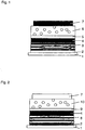
- a transparent base contact 2 is applied as an anode on a substrate 1.
- a first polymer layer as a polymeric hole transport layer 3 and a second polymer layer as a polymeric emitter layer 4 are deposited.
- This layer composite of first and second polymer layer consists of PEDOT: PSS (Baytron-P) from HCStarck, Germany.
- a first molecule layer is vapor-deposited as intermediate layer 5, which consists of a layer of 10 nm BPhen (batophenanthroline).
- BPhen bathophenanthroline
- the organic light emitting diode according to Fig.1 provided with a cover contact 7 made of aluminum.
- molecular Cs should be regarded as a non-expedient electron donating dopant, since Cs has too small a molar mass in order to be able to achieve a diffusion-stable doped layer. Therefore, doping materials with a molar mass greater than 200 g / mol, preferably greater than 400 g / mol, and a redox potential in the range of Cs are provided.
- Cs has a standard redox potential of -2.922 V and an ionization energy of 3.88 eV. The ionization energy of the dopant is less than 4.1 eV.
- Tungsten paddlewheel has an ionization potential of about 3.75 eV.
- the structure of the simple negative hpp anion is:
- the doped layer in the above example BPhen: Cs must have a conductivity in the range 1E-7 S / cm to 1E-3S / cm, preferably in a range of 1E-6S / cm to 5E-5S / cm.
- the conductivity of the undoped intermediate layer in the above example BPhen must be in a range of about 1E-10S / cm to 5E-8S / cm. The conductivity of the undoped layer is therefore at least half an order of magnitude worse than that of the doped layer.
- the preferred thickness ranges of the doped layer are between 40 nm and 500 nm, preferably 50 nm to 300 nm, that of the undoped intermediate layer between 2 nm and 30 nm, preferably between 5 nm and 15 nm.
- the undoped layer must be much thinner because of their low conductivity be as the doped layer. The considerations with respect to layer thickness and conductivity apply mutatis mutandis to the p-doping of the hole transport layer according to the following embodiment 2 below.
- This embodiment can be modified in that a single layer can occur as the polymeric hole transport layer 3 and as the polymeric emitter layer 4, which assumes both functions, and therefore only one polymer layer can be present.
- the base contact 2 may also be non-transparent (e.g., gold, aluminum) and then the cover contact 7 as a transparent cathode, e.g. by an ITO layer produced in a sputtering process. Because of the doping of the layer 6, an electron injection of ITO in layer 6 is still possible.
- the dopant concentration can be between 1: 1000 and 1:20.
- the organic light-emitting diode according to the invention consists of both polymer layers and molecular layers and can therefore meaningfully also be referred to as POLED or hybrid OLED.
- Fig. 2 An alternative embodiment, not part of the invention, is in Fig. 2 shown. she shows you one Fig. 1 electrically inverse construction.
- a base contact 2 is applied as a cathode.
- the base contact 2 is designed as a non-transparent cathode (calcium, barium or aluminum), but may also be transparent (ITO).
- a first polymer layer as a polymeric electron transport layer 8 and a second polymer layer as a polymeric emitter layer 4 are deposited.
- a first molecule layer is vapor-deposited as an intermediate layer 9, which may consist of a layer of 10 nm TPD (tri-phenyldiamine).
- a second molecular layer in the form of a hole transport and injection layer 10 of, for example, m-MTDATA doped with F4-TCNQ (tris (3-methylphenyl-phenylamino) -triphenylamine doped with tetrafluoro-tetracyanoquinodimethanes) in a molar ratio of about 50: 1.
- F4-TCNQ tris (3-methylphenyl-phenylamino) -triphenylamine doped with tetrafluoro-tetracyanoquinodimethanes
- the organic light emitting diode according to Fig. 2 provided with an anode as a cover contact 7 from eg transparent ITO.
- an anode applied as a base contact 2 so is the subsequent order of molecular doped hole injection and transport layer 10, intermediate layer 9, polymeric layer 4, intermediate layer 5 and molecular doped electron transport layer 10 and cover contact 7 as a cathode. If the cathode is applied as base contact 2 on the substrate 1, the order is inverted.
Landscapes
- Physics & Mathematics (AREA)
- Optics & Photonics (AREA)
- Engineering & Computer Science (AREA)
- Chemical & Material Sciences (AREA)
- Materials Engineering (AREA)
- Manufacturing & Machinery (AREA)
- Inorganic Chemistry (AREA)
- Spectroscopy & Molecular Physics (AREA)
- Electroluminescent Light Sources (AREA)
Description
Die Erfindung betrifft ein Licht emittierendes Bauelement mit organischen Schichten, insbesondere eine organische Leuchtdiode, bestehend aus mehreren Schichten zwischen einem Grundkontakt auf einem Substrat und einem Deckkontakt, mit als Polymerschicht, die aus Polymer besteht, ausgebildeten Schichten und mit als Molekülschicht ausgebildeten Schichten, die aus im Vakuum aufgebrachten kleinen Molekülen bestehen.The invention relates to a light-emitting component with organic layers, in particular an organic light-emitting diode, consisting of several layers between a base contact on a substrate and a cover contact, with layers formed as a polymer layer, which consists of polymer, and with layers formed as a molecule layer exist in vacuum applied small molecules.
Die Erfindung betrifft auch ein Verfahren zur Herstellung eines Licht emittierenden Bauelementes, bei dem auf ein Substrat ein Grundkontakt, danach mehrere Schichten und schließlich ein Deckkontakt aufgebracht wird.The invention also relates to a method for producing a light-emitting component, in which a base contact, then several layers and finally a cover contact is applied to a substrate.
Organische Leuchtdioden sind seit der Demonstration niedriger Arbeitsspannungen von Tang et al. 1987 [
Üblicher Weise liegt organischen Leuchtdioden in Form von PLED folgende Schichtstruktur zugrunde:
- 1. Substrat (transparent, z.B. Glas)
- 2. Anode (transparent, meistens Indium Zinn Oxid (ITO))
- 3. Löchertransport- oder Löcherinjektionsschicht (meistens PEDOT:PSS oder PANI - polyanilin mit Beimischungen wie PSS; PEDOT = polyethylenedioxythiophene, PSS = polystyrenesulfonate)
- 4. aktives Polymer (emittiert Licht)
- 5. Kathode (meist ein Metall mit niedriger Austrittsarbeit wie Barium, Calcium)
- 1. substrate (transparent, eg glass)
- 2. anode (transparent, mostly indium tin oxide (ITO))
- 3. Hole transport or hole injection layer (mostly PEDOT: PSS or PANI - polyaniline with admixtures such as PSS; PEDOT = polyethylenedioxythiophene, PSS = polystyrenesulfonate)
- 4. active polymer (emits light)
- 5. Cathode (usually a metal with low work function such as barium, calcium)
Die polymeren Schichten, d.h. die Löchertransport- oder Löcherinjektionsschicht und das aktive Polymer werden aus einer flüssigen Lösung (in Wasser oder in Lösungsmitteln) hergestellt. Die Kontakte (Anode, Kathode) typischerweise durch Vakuumprozessen.The polymeric layers, i. the hole transport or hole injection layer and the active polymer are prepared from a liquid solution (in water or in solvents). The contacts (anode, cathode) typically by vacuum processes.
Die Vorteile dieser Struktur für Anwendungen, z.B. Displays ist die Vielfältigkeit der Prozesse zur Herstellung der polymeren Schichten, darunter solche Prozesse, die eine einfache laterale Strukturierung der PLED erlauben, namentlich das Tintenstrahl(Ink-Jet)-Drucken. Bei diesem werden die unterschiedlichen Polymere der drei Farben auf vorher vorbereitete Stellen gedruckt, wodurch nebeneinanderliegende Bereiche verschiedener Emissionsfarbe entstehen.The advantages of this structure for applications, e.g. Displays are the variety of processes for making the polymeric layers, including those processes that allow easy lateral structuring of the PLED, namely inkjet (ink-jet) printing. In this case, the different polymers of the three colors are printed on previously prepared areas, creating adjacent areas of different emission color.
Der Nachteil besteht unter anderem darin, dass nicht sinnvoll mehr als zwei verschiedene polymere Schichten aufgetragen werden können, da die Lösungsmittel der Polymere so gewählt werden müssen, dass sie sich gegenseitig nicht beeinflussen, das heißt das Material der Unterlage nicht angreifen. Dies bedeutet, dass das emittierende Polymer gleichzeitig auch gut zum Elektronentransport und zur Elektroneninjektion aus der Kathode geeignet sein muss, eine Forderung, die starke Einschränkung für die Materialauswahl und die Strukturoptimierung darstellt.The disadvantage is, inter alia, that it makes sense not more than two different polymeric layers can be applied, since the solvent of the polymers must be chosen so that they do not affect each other, that is do not attack the material of the pad. This means that at the same time the emitting polymer must also be well suited for electron transport and electron injection from the cathode, a requirement that severely limits material selection and structure optimization.
Hinzu kommt, dass man die Reihenfolge der Struktur für ein gegebenes Materialsystem nur schwer ändern kann, also dass wie im obigen Fall mit der Anode angefangen werden muss. Dies ist insbesondere für die Integration der PLED auf Aktiv-Matrix Display-Substraten mit n-Kanal Transistoren als Schaltelement nachteilig. Die Verwendung transparenter Deckkontakte (auch als Kathode) ist ebenso schwierig, da diese meistens durch einen Sputterprozess hergestellt werden (z.B. ITO). Dieser zerstört aber organische Materialien. Da die oberste Schicht in einer PLED eine emittierende Schicht ist, wird die Effizienz der Lichterzeugung der organischen Leuchtdiode dadurch gesenkt. Eine Verbesserung der Stabilität gegen Sputterschäden kann durch das Einbringen einer im Vakuum aufgedampften Schicht aus kleinen Molekülen erreicht werden. Allerdings stellt auch in diesem Fall die Elektroneninjektion aus der Kathode ein Problem dar. Ein weiterer Nachteil der obigen Struktur ist es, dass man nur mit sehr instabilen Kontaktmaterialien wie Barium oder Kalzium eine effiziente Elektroneninjektion erreichen kann. Diese Materialien werden aber von Sauerstoff und Wasser angegriffen.In addition, it is difficult to change the order of the structure for a given material system, so that, as in the above case, the anode has to be started. This is particularly disadvantageous for the integration of the PLED on active matrix display substrates with n-channel transistors as a switching element. The use of transparent cover contacts (also called cathodes) is just as difficult since they are mostly made by a sputtering process (e.g., ITO). This destroys organic materials. Since the uppermost layer in a PLED is an emitting layer, the efficiency of light generation of the organic light emitting diode is thereby lowered. An improvement in sputter damage stability can be achieved by incorporating a vacuum-deposited layer of small molecules. However, electron injection from the cathode is also a problem in this case. A further disadvantage of the above structure is that only with very unstable contact materials such as barium or calcium can efficient electron injection be achieved. These materials are attacked by oxygen and water.
Organische Leuchtdioden in Form von OLEDs werden aus in Vakuum aufgedampfte kleinen Molekülen aufgebaut. Sind die Moleküle, welche die Schichten der OLED bilden sollen, klein genug, so können sie meistens ohne Zersetzung durch einen thermischen Prozess aufgebracht werden. Dazu werden die Moleküle im Vakuum (wegen der großen freien Weglänge) verdampft.Organic light-emitting diodes in the form of OLEDs are built up from small molecules vapor-deposited in vacuum. If the molecules that are to form the layers of the OLED are small enough, they can usually be applied without decomposition by a thermal process. For this purpose, the molecules are evaporated in vacuo (because of the large free path).
Um die Injektion aus den Kontakten in die organische Schicht zu verbessern und die Leitfähigkeit der Transportschichten zu erhöhen, können die Transportschichten durch Mischverdampfung mit organischen oder anorganischen Dotanden, welche Akzeptoren (für Löcherdotierung) bzw. Donatoren (für Elektronendotierung) sind, dotiert werden. Dabei müssen die Dotanden am Beginn des Verdampfungsprozesses nicht in ihrer endgültigen Form vorliegen, solange das alternativ verwendete Precursor-Material beim Verdampfungsprozess (der auch modifiziert sein kann, z.B. durch Benutzung von Elektronenstrahlen) den Dotanden bildet. Die Herstellung der gemischten Schichten erfolgt typischerweise durch Misch (Ko-)verdampfung.In order to improve the injection from the contacts into the organic layer and to increase the conductivity of the transport layers, the transport layers can be mixed evaporation with organic or inorganic dopants, which are acceptors (for hole doping) and donors (for electron doping), be doped. The dopants do not have to be in their final form at the beginning of the evaporation process, as long as the alternatively used precursor material forms the dopant during the evaporation process (which can also be modified, eg by using electron beams). The preparation of the mixed layers is typically done by mixed (co-) evaporation.
Zusätzlich zu den dotierten Transportschichten müssen dann noch intrinsische (also nicht dotierte) Zwischenschichten mit bestimmten energetischen Eigenschaften eingebracht werden (Patent
Die Struktur der OLED ist dann eine pin-Heterostruktur:
- 1. Träger, Substrat,
- 2. Elektrode, löcherinjizierend (Anode = Pluspol), vorzugsweise transparent,
- 3. p-dotierte Löcher injizierende und transportierende Schicht,
- 4. dünnere löcherseitige Blockschicht aus einem Material dessen Bandlagen zu den Bandlagen der sie umgebenden Schichten passt,
- 5. lichtemittierende Schicht,
- 6. elektronenseitige Blockschicht (typischerweise dünner als die nachfolgend genannte Schicht) aus einem Material, dessen Bandlagen zu den Bandlagen der sie umgebenden Schichten passt,
- 7. n-dotierte Elektronen injizierende und transportierende Schicht,
- 8. Elektrode, meist ein Metall mit niedriger Austrittsarbeit, elektroneninjizierend (Kathode = Minuspol)
- 1. carrier, substrate,
- 2nd electrode, hole-injecting (anode = positive pole), preferably transparent,
- 3. p-doped holes injecting and transporting layer,
- 4. thinner hole-side block layer of a material whose band layers match the band layers of the surrounding layers,
- 5. light-emitting layer,
- 6. electron-side block layer (typically thinner than the following layer) of a material whose band layers match the band layers of the surrounding layers,
- 7. n-doped electron injecting and transporting layer,
- 8. Electrode, usually a metal with low work function, electron-injecting (cathode = negative pole)
Vorteile dieser Struktur sind die getrennte Optimierbarkeit der Eigenschaften der einzelnen Schichten, der einstellbare große Abstand der Emitterschicht zu den Kontakten, die sehr gute Injektion der Ladungsträger in die organischen Schichten und die geringe Dicke der nicht gut leitfähigen Schichten (4; 5; 6). Damit lassen sich sehr niedrige Betriebsspannungen (<2,6V für 100cd/m2 Leuchtdichte) bei gleichzeitig hoher Effizienz der Lichterzeugung erreichen, wie dies in
Der Nachteil dieser Struktur besteht darin, dass eine laterale Strukturierung der OLED-Struktur zum Aufbau verschiedenfarbiger Pixel in einem Display nur über Schattenmasken erfolgen kann. Dieser Prozess hat Limitationen hinsichtlich der kleinsten erreichbaren Pixelgrößen (<50µm Subpixel). Der Schattenmaskenprozess ist in einer Fertigung ein relativ aufwendiger Prozess. Allerdings kann man den Ink-Jet Prozess bei kleinen Molekülen wegen ihrer Unlöslichkeit nicht anwenden.The disadvantage of this structure is that a lateral structuring of the OLED structure for the construction of differently colored pixels in a display can only take place via shadow masks. This process has limitations on the smallest achievable pixel sizes (<50μm subpixels). The shadow mask process is a relatively expensive process in a production. However, you can not use the ink-jet process for small molecules because of their insolubility.
In der
Aus
Dem Artikel "OLEDs with doped transport layers for highly efficient displays" von Pfeiffer et al. sind verschiedene Dotierungsmöglichkeiten in organischen Leuchtdioden zu entnehmen. Der Artikel "Closed-shell molecules that ionize more readily than cesium" von Cotton et al. beschreibt stabile Moleküle mit einem niedrigen Ionisationspotential.The article "OLEDs with doped transport layers for highly efficient displays" by Pfeiffer et al. Different doping possibilities can be found in organic light-emitting diodes. The article "Closed-shell molecules that ionize more than just cesium" by Cotton et al. describes stable molecules with a low ionization potential.
In dem Artikel "Pyronin B as a donor for n-typed doping of organic thin films" von Werner et al. wird die Verwendung von Pyronin B als ein Donator in dünnen organischen Schichten beschrieben.In the article "Pyronin B as a donor for n-typed doping of organic thin films" by Werner et al. describes the use of pyronin B as a donor in thin organic layers.
Der Artikel "Low-voltage inverted transparent vacuum deposited organic light-emitting diodes using electric doping" von Zhou et al. beschreibt die Vorteile einer elektrischen Dotierung in transparenten invertierten organischen Leuchtdioden.The article "Low-voltage inverted transparent vacuum deposited organic light-emitting diodes using electric doping" by Zhou et al. describes the advantages of an electrical doping in transparent inverted organic light-emitting diodes.
Es ist somit Aufgabe der Erfindung, die Flexibilität des Aufbaus eines Licht emittierenden Bauelementes und die Injektion von Ladungsträgern in die organischen Schichten unter Beibehaltung einer guten Strukturierbarkeit zu erhöhen.It is therefore an object of the invention to increase the flexibility of the construction of a light-emitting component and the injection of charge carriers in the organic layers while maintaining good structurability.
Diese Aufgabe wird durch ein Licht emittierendes Bauelement nach dem unabhängigen Patentauspruch 1 und ein Verfahren nach dem unabhängigen Patentanspruch 22 gelöst. Vorteilhafte Ausgestaltungen der Erfindung sind gegenstand von abhängigen Unteransprüchen.This object is achieved by a light-emitting component according to
Der Dotand soll aus einem organischen oder metall-organischen Molekül bestehen, welches eine molare Masse von größer 200g/mol bevorzugt größer 400g/mol aufweist. Dabei kommt es darauf an, dass der in der Schicht aktive Dotand diese molare Masse aufweist. Beispielsweise ist Cs2CO3 (Cäsiumcarbonat, molare Masse ca. 324g/mol) als Donator für die n-Dotierung der Elektronentransportschicht im Sinne der Erfindung nicht geeignet. Cs2CO3 als solches ist eine vergleichsweise stabile Verbindung, welche nicht mehr in der Lage ist, ein oder mehr Elektronen auf ein anderes Molekül (das Matrixmaterial) zu übertragen. Allerdings kann in einem Bedampfungsprozess oberhalb 615°C (Zersetzungstemperatur) molekulares Cs freigesetzt werde, welches in der Lage wäre, als Dotand ein Elektron auf das Matrixmaterial zu übertragen. Die molare Masse von Cs liegt aber bei ca. 132g/mol. Cäsium hat als Dotand den Nachteil, als relativ kleines Molekül bzw. Atom nicht diffussionsstabil in der Matrixschicht eingebaut zu werden, mit negativen Einflüssen auf die Lebensdauer des organischen lichtemittierenden Bauelementes. Sinngemäßes gilt im Falle der p-Dotierung der Löchertransportschicht mit einem starken Akzeptor (beim invertiertem POLED-Aufbau).The dopant should consist of an organic or metal-organic molecule which has a molar mass of greater than 200 g / mol, preferably greater than 400 g / mol. It is important that the dopant active in the layer has this molar mass. For example, Cs 2 CO 3 (cesium carbonate, molar mass about 324 g / mol) is not suitable as donor for the n-doping of the electron transport layer according to the invention. As such, Cs 2 CO 3 is a comparatively stable compound which is no longer able to transfer one or more electrons to another molecule (the matrix material). However, in a sputtering process above 615 ° C (decomposition temperature) molecular Cs could be released, which would be able to transfer an electron as dopant to the matrix material. The molar mass of Cs is around 132g / mol. As a dopant, cesium has the disadvantage of being incorporated in the matrix layer as a relatively small molecule or atom that is not resistant to diffusion, with negative influences on the service life of the organic light-emitting component. The same applies in the case of p-doping of the hole transport layer with a strong acceptor (the inverted POLED structure).
Die beiden molekularen aufgedampften Schichten sind die undotierte Zwischenschicht (Bezugsziffer 5 in dem nachfolgend beschriebenen Ausführungsbeispiel) und die dotierte Transportschicht. Da die energetische Barriere der Ladungsträgerinjektion von der dotierten Transportschicht in die polymer Emitterschicht für gebräuchliche Emitterpolymere wie Poly-phenylenvinylen, PPV, (im Falle der herkömmlich bekannten Schichtstruktur mit polymer Löchertransportschicht auf einem Substrat die Barriere zur Injektion der Elektronen) zu groß ist, muss eine undotierte Zwischenschicht eingefügt werden, welche wesentlich dünner als die dotierte Transportschicht ist und deren LUMO Energieniveau (LUMO: niedrigstes unbesetztes Molekülorbital) im Falle der Löchertransportschicht allerdings das HOMO Energieniveau (HOMO: höchstes besetztes Molekülorbital) zwischen der dotierten Transportschicht und der Emissionspolymerschicht liegen muss. Das hat zum einen die Folge, dass einerseits Ladungsträger besser in die Emitterpolymerschicht injiziert werden können, andererseits auch nicht-strahlende Rekombinationsprozesse an der Grenzfläche von der Emitterpolymerschicht zur der dotierten Transportschicht auftreten, wobei üblicherweise diese bei hohen energetischen Barrieren nahezu zwangsläufig auftreten.The two molecular deposited layers are the undoped interlayer (reference numeral 5 in the embodiment described below) and the doped transport layer. Since the energetic barrier of carrier injection from the doped transport layer into the polymer emitter layer for common emitter polymers such as poly-phenylenevinylene, PPV (in the case of the conventionally known layer structure with polymer hole transport layer on a substrate, the barrier for injection of the electrons) is too large, one must However, in the case of the hole transport layer, the HOMO energy level (HOMO: highest occupied molecular orbital) between the doped transport layer and the emission polymer layer must be LUMO energy level (LUMO: lowest unoccupied molecular orbital). This has the consequence, on the one hand, that charge carriers can be better injected into the emitter polymer layer and, on the other hand, that non-radiative recombination processes occur at the interface between the emitter polymer layer and the doped transport layer, whereby these usually occur almost inevitably at high energy barriers.
Vorteilhafterweise erfolgt die Dotierung der Molekülschicht in einem Vakuum aus zwei separat geregelten Quellen als eine Mischverdampfung.Advantageously, the doping of the molecular layer takes place in a vacuum from two separately controlled sources as a mixed evaporation.
Der Auftrag der Polymerschichten kann dabei mit einfachen Mitteln sehr präzise erfolgen. Diese Strukturierung dient dann gleichzeitig der Strukturierung des späteren Licht emittierenden Bauelementes, ohne dass aufwändige Strukturierungsschritte oder -mittel erforderlich sind. Die Aufbringung von Molekülschichten hingegen vermeidet es, dass in Folge des Vorhandenseins von in der Regel nur zwei disjunkten Lösungsmitteln die Modifikation von Polymerschichten sehr beschränkt ist und erhöht die Möglichkeit des Aufbaues verschiedenster Schichtkombinationen.The order of the polymer layers can be done with simple means very precise. This structuring then simultaneously serves to structure the later light-emitting component, without the need for complex structuring steps or means. By contrast, the application of molecular layers avoids that the modification of polymer layers is very limited as a result of the presence of usually only two disjoint solvents and increases the possibility of building a wide variety of layer combinations.
Die Erfindung soll nachfolgend anhand eines Ausführungsbeispieles näher erläutert werden.The invention will be explained in more detail with reference to an embodiment.
In den zugehörigen Zeichnungen zeigt
- Fig. 1
- einen ersten Schichtaufbau einer erfindungsgemäßen organischen Leuchtdiode,
- Fig. 2
- einen zweiten, zur
Fig. 1 elektrisch inversen Schichtaufbau einer organischen Leuchtdiode.
- Fig. 1
- a first layer structure of an organic light-emitting diode according to the invention,
- Fig. 2
- a second, to
Fig. 1 electrically inverse layer structure of an organic light-emitting diode.
Wie in
Molekulares Cs ist in diesem Zusammenhang als ein nicht zweckmäßiger Elektronen abgebender Dotand anzusehen, da Cs eine zu kleine molare Masse aufweist, um damit eine diffussionstabile dotierte Schicht erzielen zu können. Vorgesehen sind daher Dotiermaterialien mit einer molaren Masse größer 200 g/mol, bevorzugt größer 400 g/mol, und ein Redoxpotential im Bereich von Cs aufweisen. Cs hat ein Standardredoxpotential von -2,922 V und eine Ionisationsenergie von 3,88 eV. Die Ionisationsenergie des Dotanden ist kleiner als 4,1 eV.In this context, molecular Cs should be regarded as a non-expedient electron donating dopant, since Cs has too small a molar mass in order to be able to achieve a diffusion-stable doped layer. Therefore, doping materials with a molar mass greater than 200 g / mol, preferably greater than 400 g / mol, and a redox potential in the range of Cs are provided. Cs has a standard redox potential of -2.922 V and an ionization energy of 3.88 eV. The ionization energy of the dopant is less than 4.1 eV.
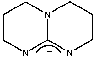
Ein Beispiel für einen dieser Dotanden ist Wolfram-Paddlewheel [W2(hpp)4] :

Wolfram-Paddlewheel hat ein Ionisationspotential von ca. 3,75 eV. Die Struktur des einfach negativen hpp-Anions lautet:
Aus Vergleichen mit dem Gas-Ionisationspotentiale von molekularem Cs von 3,9 eV und der Elektronenaffinität von BPhen als Schicht von ca. 2,4eV kann man abschätzen, dass es erforderlich ist, dass der Donator-Dotand für OLED-Transportmaterialien ein Ionisationspotential von kleiner als 4,1eV aufweist.From comparisons with the gas ionization potentials of molecular Cs of 3.9 eV and the electron affinity of BPhen as a layer of approximately 2.4 eV, it can be estimated that it is necessary for the donor dopant for OLED transport materials to have an ionization potential of smaller as 4.1eV.
Die dotierte Schicht (im obigen bsp. BPhen:Cs) muss eine Leitfähigkeit im Bereich 1E-7 S/cm bis 1E-3S/cm, bevorzugt in einem Bereich von 1E-6S/cm bis 5E-5S/cm, aufweisen. Die Leitfähigkeit der undotierten Zwischenschicht (im obigen Bsp. BPhen) muss in einem Bereich von ca. 1E-10S/cm bis 5E-8S/cm liegen. Die Leitfähigkeit der undotierten Schicht ist also wenigstens eine halbe Größenordnung schlechter als die der dotierten Schicht. Die bevorzugten Dickenbereiche der dotierten Schicht liegen zwischen 40 nm und 500 nm, bevorzugt 50 nm bis 300 nm, die der undotierten Zwischenschicht zwischen 2 nm und 30 nm, bevorzugt zwischen 5 nm und 15 nm. Die undotierte Schicht muss wegen ihrer geringen Leitfähigkeit wesentlich dünner als die dotierte Schicht sein. Die Betrachtungen hinsichtlich Schichtdicke und Leitfähigkeit gelten sinngemäß auch für die p-Dotierung der Löchertransportschicht nach dem weiter unten folgenden Ausführungsbeispiel 2.The doped layer (in the above example BPhen: Cs) must have a conductivity in the range 1E-7 S / cm to 1E-3S / cm, preferably in a range of 1E-6S / cm to 5E-5S / cm. The conductivity of the undoped intermediate layer (in the above example BPhen) must be in a range of about 1E-10S / cm to 5E-8S / cm. The conductivity of the undoped layer is therefore at least half an order of magnitude worse than that of the doped layer. The preferred thickness ranges of the doped layer are between 40 nm and 500 nm, preferably 50 nm to 300 nm, that of the undoped intermediate layer between 2 nm and 30 nm, preferably between 5 nm and 15 nm. The undoped layer must be much thinner because of their low conductivity be as the doped layer. The considerations with respect to layer thickness and conductivity apply mutatis mutandis to the p-doping of the hole transport layer according to the
Diese Ausführungsform kann dadurch modifiziert werden, dass als polymere Löchertransportschicht 3 und als polymere Emitterschicht 4 eine einzige Schicht auftreten kann, die beide Funktionen übernimmt, mithin also nur eine Polymerschicht vorhanden sein kann. Des Weiteren kann der Grundkontakt 2 auch nichttransparent ausgebildet sein (z.B. Gold, Aluminium) und dann den Deckkontakt 7 als Kathode transparent, z.B. durch eine in einem Sputterprozess hergestellte ITO-Schicht. Wegen der Dotierung der Schicht 6 ist eine Elektroneninjektion von ITO in Schicht 6 immer noch möglich. Ferner kann die Dotanden-Konzentration im Falle organischer Dotanden zwischen 1:1000 und 1:20 liegen.This embodiment can be modified in that a single layer can occur as the polymeric hole transport layer 3 and as the
Wie ersichtlich, besteht die erfindungsgemäße organische Leuchtdiode sowohl aus Polymer- wie auch aus Molekülschichten und kann deshalb sinnvoll auch als POLED oder hybride OLED bezeichnet werden.As can be seen, the organic light-emitting diode according to the invention consists of both polymer layers and molecular layers and can therefore meaningfully also be referred to as POLED or hybrid OLED.
Eine alternative Ausführungsform, nicht Teil der Erfindung, ist in
Weitere nicht näher dargestellte Ausführungsformen, nicht Teil der Erfindung, bestehen
darin, die Reihenfolge der Polymer- und Molekülschichten zu vertauschen, dass heißt, erst auf das Substrat 1 dem Grundkontakt 2 eine dotierte Molekülschicht 10 oder 6 aufzubringen, und im Anschluss daran die lateral strukturierbaren Polymerschichten 4 und 8 oder 3 aufzubringen. Weiterhin alternativ dazu ist eine Ausführung möglich, bei der eine aktive polymer Emitterschicht 4 von organischen Molekülschichten umrahmt wird.Other embodiments not shown, not part of the invention, exist
to interchange the order of the polymer and molecular layers, that is to first apply a doped
Ist auf dem Substrat 1 eine Anode als Grundkontakt 2 aufgebracht, so ist die
anschließende Reihenfolge molekulare dotierte Löcherinjektions- und -transportschicht 10, Zwischenschicht 9, polymere Schicht 4, Zwischenschicht 5 und molekulare dotierte Elektronentransportschicht 10 und Deckkontakt 7 als Kathode. Ist die Kathode als Grundkontakt 2 auf dem Substrat 1 aufgebracht, so ist die Reihenfolge invertiert.Is on the
subsequent order of molecular doped hole injection and
- 11
- Substratsubstratum
- 22
- Grundkontaktbasic Contact
- 33
- polymere Löchertransportschichtpolymeric hole transport layer
- 44
- polymere Emitterschichtpolymeric emitter layer
- 55
- Zwischenschicht (Molekülschicht)Interlayer (molecular layer)
- 66
- dotierte Elektronentransport- und Injektionsschicht (Molekülschicht)doped electron transport and injection layer (molecular layer)
- 77
- Deckkontaktdeck Contact
- 88th
- polymere Elektronentransportschichtpolymeric electron transport layer
- 99
- Zwischenschicht (Molekülschicht)Interlayer (molecular layer)
- 1010
- dotierte Löchertransport- und Injektionsschicht (Molekülschicht)doped hole transport and injection layer (molecular layer)
Claims (29)
- A light emitting component with organic layers consisting of a plurality of layers between a bottom contact on a substrate and a top contact, with polymer layers from a polymer and with molecular layers from small molecules applied in a vacuum, wherein at least one polymer layer (3; 4) and two molecular layers (5; 6) are arranged, wherein- the top contact (7) is a cathode and the layer nearest the top contact (7) is configured as an electron-transporting molecular layer n-doped with an organic donor material, wherein the n-doped molecular layer comprises an organic main substance forming a matrix material and the donor material, characterised in that the donor material has an ionisation potential of less than 4.1eV and the molecular mass of the donor material is larger than 200g/mol.
- The light-emitting component according to claim 1, characterised in that a polymer layer is arranged simultaneously forming an emitter layer and a transport layer.
- The light-emitting component according to claim 1 or 2, characterised in that more than two polymer layers are arranged.
- The light-emitting component according to one of claims 1 to 3, characterised in that only one molecular layer is arranged which is doped.
- The light-emitting component according to one of claims 1 to 3, characterised in that the matrix material of the doped molecular layer (9) is equal to a matrix material of an undoped intermediate layer (5).
- The light-emitting component according to one of claims 1 to 5, characterised in that one or more doped or undoped molecular layers are arranged on the bottom contact (2) and one more polymer layers are arranged on the side facing away from the bottom contact.
- The light-emitting component according to one of claims 1 or 2, characterised in that a polymer layer is arranged, adjacent to which a molecular layer is arranged both on the side facing the bottom contact (2) and on the side facing the top contact (7).
- The light-emitting component according to one of claims 1 to 7, characterised in that the top contact (7) and the bottom contact (2) are transparent.
- The light-emitting component according to one of claims 1 to 8, characterised in that it consists of a multiple arrangement of identical light-emitting components which are electrically connected with each other by means of a connecting layer.
- The light-emitting component according to claim 9, characterised in that the connecting layer is provided with a contact and can be activated via the same.
- The light-emitting component according to claim 9 or 10, characterised in that the connecting layer and/or the contact are transparent.
- The light-emitting component according to one of claims 1 to 11, characterised in that the donor doping agent in the electron transporting layer is Wolfram-Paddlewheel [W2(hpp)4] with hpp = 1,3,4,6,7,8-hexahydro-2H-pyrimido-[1,2-a]-pyrimidin.
- The light-emitting component according to one of claims 1 to 12, characterised in that the doped molecular layer has a conductivity from 1E-7S/cm to 1E-3S/cm.
- The light-emitting component according to one of claims 1 to 12, characterised in that the doped molecular layer has a conductivity from 1E-6S/cm to 1E-5S/cm.
- The light-emitting component according to claim 5 or one of claims 6 to 14 insofar as referred back to claim 5, characterised in that the conductivity of the undoped intermediate layer is less by at least half a magnitude than the conductivity of the doped molecular layer.
- The light-emitting component according to one of claims 1 to 15, characterised in that the doped molecular layer has a thickness from 40 nm to 500 nm.
- The light-emitting component according to one of claims 1 to 15, characterised in that the doped molecular layer has a thickness from 50 nm to 300 nm.
- The light-emitting component according to claim 5 or one of claims 6 to 17 insofar as referred back to claim 5, characterised in that the undoped intermediate layer has a thickness from 2 nm to 30 nm.
- The light-emitting component according to claim 5 or one of claims 6 to 18 insofar as referred back to claim 5, characterised in that the undoped intermediate layer has a thickness from 5 nm to 15 nm.
- The light-emitting component according to claim 5 or one of claims 6 to 19 insofar as referred back to claim 5, characterised in that the undoped intermediate layer is thinner than the doped molecular layer.
- The light-emitting component according to one of claims 1 to 20, characterised in that the concentration of the doping agent lies between 1:1000 and 1:20.
- A method for manufacturing a light emitting component according to one of claims 1 to 21, where a bottom contact is applied to a substrate followed by several layers and finally a top contact is applied, wherein at least one of the layers is applied as a polymer layer and several of the layers are applied as molecular layers, and wherein one of the molecular layers is doped, wherein the top contact (7) is formed as a cathode and a layer nearest the top contact (7) is formed as an electron-transporting organic n-doped molecular layer, wherein the n-doped molecular layer is formed with an organic main substance forming a matrix material and the donor material, characterised in that the donor material comprises an ionisation potential of less than 4.1eV and a molecular mass of larger than 200 g/mol.
- The method according to claim 22, characterised in that doping of the molecular layer is carried out in a vacuum of two separately controlled sources as a mixed vaporisation.
- The method according to claim 22, characterised in that the concentration of the doping agent is between 1:1000 and 1:20.
- The method according to one of claims 22 to 24, characterised in that application of the polymer layer is carried out according to the principle of inkjet printing.
- The method according to claim 25, characterised in that the emission layer (4) for manufacturing a multi-colour OLED is structured laterally by means of inkjet printing such that red, green and blue pixels are formed next to each other.
- The method according to one of claims 22 to 26, characterised in that the thickness of all layers is from 0.1 nm to 1 µm.
- The method according to one of claims 22 to 27, characterised in that at least one of the molecular layers is manufactured and doped by applying a mixed layer from a solution or by sequentially applying the materials with subsequent diffusion of the doping agents into the molecular layer.
- The method according to one of claims 22 to 28, characterised in that in the electron transporting layer the donor doping agent used is Wolfram-Paddlewheel [W2(hpp)4] with hpp = 1,3,4,6,7,8-hexahydro-2H-pyrimido-[1,2-a]-pyrimidin.
Applications Claiming Priority (2)
| Application Number | Priority Date | Filing Date | Title |
|---|---|---|---|
| DE10339772A DE10339772B4 (en) | 2003-08-27 | 2003-08-27 | Light emitting device and method for its production |
| DE10339772 | 2003-08-27 |
Publications (3)
| Publication Number | Publication Date |
|---|---|
| EP1511094A2 EP1511094A2 (en) | 2005-03-02 |
| EP1511094A3 EP1511094A3 (en) | 2005-07-27 |
| EP1511094B1 true EP1511094B1 (en) | 2017-02-22 |
Family
ID=34089248
Family Applications (1)
| Application Number | Title | Priority Date | Filing Date |
|---|---|---|---|
| EP04018867.4A Expired - Lifetime EP1511094B1 (en) | 2003-08-27 | 2004-08-10 | Light emitting device and method of fabrication |
Country Status (7)
| Country | Link |
|---|---|
| US (3) | US7355197B2 (en) |
| EP (1) | EP1511094B1 (en) |
| JP (1) | JP5184736B2 (en) |
| KR (1) | KR100685108B1 (en) |
| CN (1) | CN100559627C (en) |
| DE (1) | DE10339772B4 (en) |
| TW (1) | TWI264841B (en) |
Families Citing this family (99)
| Publication number | Priority date | Publication date | Assignee | Title |
|---|---|---|---|---|
| US20100026176A1 (en) | 2002-03-28 | 2010-02-04 | Jan Blochwitz-Nomith | Transparent, Thermally Stable Light-Emitting Component Having Organic Layers |
| DE10339772B4 (en) | 2003-08-27 | 2006-07-13 | Novaled Gmbh | Light emitting device and method for its production |
| TWI238677B (en) | 2003-12-25 | 2005-08-21 | Fujitsu Ltd | Organic EL element, organic EL display, process for fabricating organic EL element, and device for fabricating organic EL element |
| US7540978B2 (en) * | 2004-08-05 | 2009-06-02 | Novaled Ag | Use of an organic matrix material for producing an organic semiconductor material, organic semiconductor material and electronic component |
| KR101027896B1 (en) | 2004-08-13 | 2011-04-07 | 테크니셰 유니베르시테트 드레스덴 | Layer Assembly for Luminescent Components |
| DE602004006275T2 (en) * | 2004-10-07 | 2007-12-20 | Novaled Ag | Method for doping a semiconductor material with cesium |
| FR2878652A1 (en) * | 2004-11-29 | 2006-06-02 | Thomson Licensing Sa | ORGANIC ELECTROLUMINESCENT DIODE WITH DOPED LAYERS |
| WO2006062177A1 (en) * | 2004-12-06 | 2006-06-15 | Semiconductor Energy Laboratory Co., Ltd. | Composite material including organic compound and inorganic compound, light-emitting element and light-emitting device using the composite compound, and manufacturing method of the light-emitting element |
| EP1705727B1 (en) * | 2005-03-15 | 2007-12-26 | Novaled AG | Light emitting element |
| EP2284923B1 (en) * | 2005-04-13 | 2016-12-28 | Novaled GmbH | Assembly for an organic pin-type LED and manufacturing method |
| US8487527B2 (en) | 2005-05-04 | 2013-07-16 | Lg Display Co., Ltd. | Organic light emitting devices |
| US7777407B2 (en) | 2005-05-04 | 2010-08-17 | Lg Display Co., Ltd. | Organic light emitting devices comprising a doped triazine electron transport layer |
| US7750561B2 (en) | 2005-05-20 | 2010-07-06 | Lg Display Co., Ltd. | Stacked OLED structure |
| US7728517B2 (en) | 2005-05-20 | 2010-06-01 | Lg Display Co., Ltd. | Intermediate electrodes for stacked OLEDs |
| US7811679B2 (en) | 2005-05-20 | 2010-10-12 | Lg Display Co., Ltd. | Display devices with light absorbing metal nanoparticle layers |
| US7943244B2 (en) | 2005-05-20 | 2011-05-17 | Lg Display Co., Ltd. | Display device with metal-organic mixed layer anodes |
| US7795806B2 (en) | 2005-05-20 | 2010-09-14 | Lg Display Co., Ltd. | Reduced reflectance display devices containing a thin-layer metal-organic mixed layer (MOML) |
| EP1727221B1 (en) * | 2005-05-27 | 2010-04-14 | Novaled AG | Transparent organic light emitting diode |
| EP1729346A1 (en) * | 2005-06-01 | 2006-12-06 | Novaled AG | Light-emitting device with an electrode arrangement |
| EP1739765A1 (en) * | 2005-07-01 | 2007-01-03 | Novaled AG | Organic light-emitting diode and stack of organic light emitting diodes |
| TWI321968B (en) | 2005-07-15 | 2010-03-11 | Lg Chemical Ltd | Organic light meitting device and method for manufacturing the same |
| US7635858B2 (en) * | 2005-08-10 | 2009-12-22 | Au Optronics Corporation | Organic light-emitting device with improved layer conductivity distribution |
| JP2007059783A (en) * | 2005-08-26 | 2007-03-08 | Showa Denko Kk | Organic EL device, method for producing the same, and use thereof |
| EP1786050B1 (en) * | 2005-11-10 | 2010-06-23 | Novaled AG | Doped organic semiconductor material |
| DE502005004675D1 (en) * | 2005-12-21 | 2008-08-21 | Novaled Ag | Organic component |
| US7919010B2 (en) * | 2005-12-22 | 2011-04-05 | Novaled Ag | Doped organic semiconductor material |
| EP1804309B1 (en) | 2005-12-23 | 2008-07-23 | Novaled AG | Electronic device with a layer structure of organic layers |
| EP1804308B1 (en) * | 2005-12-23 | 2012-04-04 | Novaled AG | An organic light emitting device with a plurality of organic electroluminescent units stacked upon each other |
| EP1808909A1 (en) | 2006-01-11 | 2007-07-18 | Novaled AG | Electroluminescent light-emitting device |
| JP2009526370A (en) * | 2006-02-09 | 2009-07-16 | キユーデイー・ビジヨン・インコーポレーテツド | Devices and methods comprising layers comprising semiconductor nanocrystals and doped organic materials |
| FR2897983A1 (en) * | 2006-02-27 | 2007-08-31 | Thomson Licensing Sa | ELECTROLUMINESCENT DIODE WITH INJECTION LAYER AND TRANSPORT OF CONDUCTIVE POLYMER HOLES |
| KR101367585B1 (en) * | 2006-02-28 | 2014-02-25 | 꼼미사리아 아 레네르지 아토미끄 에뜨 옥스 에너지스 앨터네이티브즈 | Electronic component comprising a p-doped organic semiconductor |
| EP1994118B1 (en) * | 2006-03-14 | 2018-10-17 | LG Chem, Ltd. | Organic light emitting diode having high efficiency and process for fabricating the same |
| EP1837927A1 (en) * | 2006-03-22 | 2007-09-26 | Novaled AG | Use of heterocyclic radicals for doping of organic semiconductors |
| ATE394800T1 (en) * | 2006-03-21 | 2008-05-15 | Novaled Ag | HETEROCYCLIC RADICAL OR DIRADICAL, THEIR DIMERS, OLIGOMERS, POLYMERS, DISPIR COMPOUNDS AND POLYCYCLES, THEIR USE, ORGANIC SEMICONDUCTIVE MATERIAL AND ELECTRONIC COMPONENT |
| JP5683104B2 (en) * | 2006-03-21 | 2015-03-11 | ノヴァレッド・アクチエンゲゼルシャフト | Process for the production of doped organic semiconductor materials and formulations used therefor |
| EP1848049B1 (en) * | 2006-04-19 | 2009-12-09 | Novaled AG | Light emitting device |
| EP2020694A4 (en) | 2006-04-20 | 2009-05-20 | Idemitsu Kosan Co | ORGANIC ELECTROLUMINESCENCE DEVICE |
| CN101444142A (en) | 2006-05-11 | 2009-05-27 | 出光兴产株式会社 | organic electroluminescent element |
| KR101362614B1 (en) | 2006-05-11 | 2014-02-12 | 이데미쓰 고산 가부시키가이샤 | Organic electroluminescence element |
| JPWO2008015949A1 (en) | 2006-08-04 | 2009-12-24 | 出光興産株式会社 | Organic electroluminescence device |
| DE102007012794B3 (en) * | 2007-03-16 | 2008-06-19 | Novaled Ag | Pyrido [3,2-h] quinazolines and / or their 5,6-dihydro derivatives, their method of preparation and doped organic semiconductor material containing them |
| DE102007019260B4 (en) * | 2007-04-17 | 2020-01-16 | Novaled Gmbh | Non-volatile organic storage element |
| DE102007018456B4 (en) * | 2007-04-19 | 2022-02-24 | Novaled Gmbh | Use of main group element halides and/or pseudohalides, organic semiconducting matrix material, electronic and optoelectronic components |
| EP3076451B1 (en) * | 2007-04-30 | 2019-03-06 | Novaled GmbH | Oxocarbon, pseudo oxocarbon and radial compounds and their use |
| EP1990847B1 (en) * | 2007-05-10 | 2018-06-20 | Novaled GmbH | Use of quinoid bisimidazoles and their derivatives as dopant for doping an organic semi-conductor matrix material |
| DE102007031220B4 (en) | 2007-07-04 | 2022-04-28 | Novaled Gmbh | Quinoid compounds and their use in semiconducting matrix materials, electronic and optoelectronic components |
| JP2009076865A (en) | 2007-08-29 | 2009-04-09 | Fujifilm Corp | Organic electroluminescence device |
| KR101548382B1 (en) | 2007-09-14 | 2015-08-28 | 유디씨 아일랜드 리미티드 | Organic electroluminescence device |
| US7982216B2 (en) | 2007-11-15 | 2011-07-19 | Fujifilm Corporation | Thin film field effect transistor with amorphous oxide active layer and display using the same |
| JP5489446B2 (en) | 2007-11-15 | 2014-05-14 | 富士フイルム株式会社 | Thin film field effect transistor and display device using the same |
| DE102008024517A1 (en) | 2007-12-27 | 2009-07-02 | Osram Opto Semiconductors Gmbh | Radiation-emitting body and method for producing a radiation-emitting body |
| JP5243972B2 (en) | 2008-02-28 | 2013-07-24 | ユー・ディー・シー アイルランド リミテッド | Organic electroluminescence device |
| JP4555358B2 (en) | 2008-03-24 | 2010-09-29 | 富士フイルム株式会社 | Thin film field effect transistor and display device |
| JP4531836B2 (en) | 2008-04-22 | 2010-08-25 | 富士フイルム株式会社 | Organic electroluminescent device, novel platinum complex compound and novel compound that can be a ligand |
| US8057712B2 (en) * | 2008-04-29 | 2011-11-15 | Novaled Ag | Radialene compounds and their use |
| GB2461527B (en) * | 2008-07-01 | 2011-08-03 | Limited Cambridge Display Technology | Organic electronic device |
| DE102008036062B4 (en) | 2008-08-04 | 2015-11-12 | Novaled Ag | Organic field effect transistor |
| DE102008036063B4 (en) | 2008-08-04 | 2017-08-31 | Novaled Gmbh | Organic field effect transistor |
| DE102008056391B4 (en) * | 2008-09-26 | 2021-04-01 | Osram Oled Gmbh | Organic electronic component and process for its manufacture |
| DE102008054052A1 (en) | 2008-10-30 | 2010-05-06 | Osram Opto Semiconductors Gmbh | Organic, radiation-emitting component and method for producing such |
| JP2010153820A (en) | 2008-11-21 | 2010-07-08 | Fujifilm Corp | Organic electroluminescent element |
| DE102008061843B4 (en) | 2008-12-15 | 2018-01-18 | Novaled Gmbh | Heterocyclic compounds and their use in electronic and optoelectronic devices |
| JP2010182449A (en) | 2009-02-03 | 2010-08-19 | Fujifilm Corp | Organic electroluminescent display device |
| JP2010186723A (en) | 2009-02-13 | 2010-08-26 | Fujifilm Corp | Organic el device and method of manufacturing the same |
| JP2010205650A (en) | 2009-03-05 | 2010-09-16 | Fujifilm Corp | Organic el display device |
| US20100295444A1 (en) | 2009-05-22 | 2010-11-25 | Idemitsu Kosan Co., Ltd. | Organic electroluminescence device |
| US20100295445A1 (en) | 2009-05-22 | 2010-11-25 | Idemitsu Kosan Co., Ltd. | Organic electroluminescent device |
| KR102011228B1 (en) | 2009-07-31 | 2019-08-14 | 유디씨 아일랜드 리미티드 | Organic electroluminescent element |
| JP2011060549A (en) | 2009-09-09 | 2011-03-24 | Fujifilm Corp | Optical member for organic el device, and organic el device |
| JP5657243B2 (en) | 2009-09-14 | 2015-01-21 | ユー・ディー・シー アイルランド リミテッド | Color filter and light emitting display element |
| KR101094282B1 (en) | 2009-12-04 | 2011-12-19 | 삼성모바일디스플레이주식회사 | Organic light emitting device |
| WO2011073189A2 (en) | 2009-12-18 | 2011-06-23 | Novaled Ag | Large area light emitting device comprising organic light emitting diodes |
| JPWO2011102249A1 (en) * | 2010-02-17 | 2013-06-17 | コニカミノルタ株式会社 | Organic electronic device manufacturing method and organic electronic device |
| EP2367215A1 (en) * | 2010-03-15 | 2011-09-21 | Novaled AG | An organic photoactive device |
| JP2011222831A (en) | 2010-04-12 | 2011-11-04 | Idemitsu Kosan Co Ltd | Organic electroluminescent element |
| WO2011131185A1 (en) | 2010-04-21 | 2011-10-27 | Novaled Ag | Mixture for producing a doped semiconductor layer |
| KR101766709B1 (en) | 2010-04-27 | 2017-08-09 | 노발레드 게엠베하 | Organic semiconducting material and electronic component |
| JP5315420B2 (en) | 2010-07-09 | 2013-10-16 | 出光興産株式会社 | IMIDAZOPYRIDINE DERIVATIVE AND ORGANIC ELECTROLUMINESCENT DEVICE COMPRISING THE SAME |
| EP2602839A1 (en) | 2010-08-05 | 2013-06-12 | Idemitsu Kosan Co., Ltd. | Organic electroluminescent element |
| DE102010046040B4 (en) | 2010-09-22 | 2021-11-11 | Novaled Gmbh | Process for the production of fullerene derivatives |
| EP2626346B1 (en) | 2010-10-08 | 2018-01-10 | Idemitsu Kosan Co., Ltd. | Benzo[k]fluoranthene derivative and organic electroluminescence element containing same |
| KR101482362B1 (en) | 2010-11-22 | 2015-01-13 | 이데미쓰 고산 가부시키가이샤 | Organic electroluminescence device |
| KR20140015319A (en) | 2011-02-02 | 2014-02-06 | 이데미쓰 고산 가부시키가이샤 | Nitrogenated heterocyclic derivative, electron-transporting material for organic electroluminescent elements, and organic electroluminescent element using same |
| TWI526418B (en) | 2011-03-01 | 2016-03-21 | 諾瓦發光二極體股份公司 | Organic semiconductor materials and organic compositions |
| JP2013033872A (en) * | 2011-08-03 | 2013-02-14 | Sumitomo Chemical Co Ltd | Organic electroluminescent element |
| JP6107605B2 (en) * | 2013-11-05 | 2017-04-05 | コニカミノルタ株式会社 | Organic electroluminescence element and lighting device |
| CN105874575B (en) | 2013-12-16 | 2019-04-16 | 国立大学法人北陆先端科学技术大学院大学 | Semiconductor device, method for manufacturing the same, and aliphatic polycarbonate |
| CN111454297A (en) | 2014-05-08 | 2020-07-28 | 环球展览公司 | Stable imidazophenanthridine material |
| EP3002797B1 (en) | 2014-09-30 | 2020-04-29 | Novaled GmbH | A light emitting organic device and an active OLED display |
| TWI566028B (en) * | 2015-02-17 | 2017-01-11 | Zao-Lun Zhang | Flashing device for electronic equipment |
| KR102584846B1 (en) | 2015-05-05 | 2023-10-04 | 유니버셜 디스플레이 코포레이션 | Organic electroluminescent materials and devices |
| CN108349987A (en) | 2015-11-04 | 2018-07-31 | 出光兴产株式会社 | Benzimidazole fused heteroaromatics |
| WO2017109722A1 (en) | 2015-12-21 | 2017-06-29 | Idemitsu Kosan Co., Ltd. | Nitrogen-containing heterocyclic compounds and organic electroluminescence devices containing them |
| WO2017221999A1 (en) | 2016-06-22 | 2017-12-28 | Idemitsu Kosan Co., Ltd. | Specifically substituted benzofuro- and benzothienoquinolines for organic light emitting diodes |
| US10930864B2 (en) | 2017-05-10 | 2021-02-23 | Universal Display Corporation | Organic electroluminescent materials and devices |
| EP3418285B1 (en) | 2017-06-20 | 2020-05-06 | Idemitsu Kosan Co., Ltd. | Composition comprising a substituted ir complex and a phenylquinazoline bridged with a heteroatom |
| EP3466954A1 (en) | 2017-10-04 | 2019-04-10 | Idemitsu Kosan Co., Ltd. | Fused phenylquinazolines bridged with a heteroatom |
| EP3492480B1 (en) | 2017-11-29 | 2021-10-20 | Universal Display Corporation | Organic electroluminescent materials and devices |
Family Cites Families (30)
| Publication number | Priority date | Publication date | Assignee | Title |
|---|---|---|---|---|
| JPH10270171A (en) * | 1997-01-27 | 1998-10-09 | Junji Kido | Organic electroluminescent device |
| DE69822480T2 (en) | 1997-09-05 | 2004-08-12 | Cambridge Display Technology Ltd. | TRANSPORT LAYERS IN SELF-ASSEMBLY TECHNOLOGY FOR OLED'S |
| WO1999048337A1 (en) * | 1998-03-13 | 1999-09-23 | Cambridge Display Technology Ltd. | Electroluminescent devices |
| JP3468089B2 (en) | 1998-04-07 | 2003-11-17 | 松下電器産業株式会社 | Organic electroluminescent device |
| JP3776600B2 (en) * | 1998-08-13 | 2006-05-17 | Tdk株式会社 | Organic EL device |
| DE69841627D1 (en) * | 1998-12-15 | 2010-06-02 | Max Planck Inst Fuer Polymerfo | Functional material-containing polyimide layer, device using it, and method of making this device |
| JP2000196140A (en) | 1998-12-28 | 2000-07-14 | Sharp Corp | Organic electroluminescent device and manufacturing method thereof |
| US6639357B1 (en) | 2000-02-28 | 2003-10-28 | The Trustees Of Princeton University | High efficiency transparent organic light emitting devices |
| DE10058578C2 (en) * | 2000-11-20 | 2002-11-28 | Univ Dresden Tech | Light-emitting component with organic layers |
| IL156038A0 (en) * | 2000-11-29 | 2003-12-23 | Method and system for conducting fully antomated survey research | |
| ATE415802T1 (en) * | 2000-12-20 | 2008-12-15 | Koninkl Philips Electronics Nv | ELECTROLUMINESCENCE COLOR DISPLAY PANEL |
| JP3898442B2 (en) | 2000-12-25 | 2007-03-28 | 三星エスディアイ株式会社 | Organic electroluminescence device |
| US6998487B2 (en) * | 2001-04-27 | 2006-02-14 | Lg Chem, Ltd. | Double-spiro organic compounds and organic electroluminescent devices using the same |
| US6784016B2 (en) * | 2001-06-21 | 2004-08-31 | The Trustees Of Princeton University | Organic light-emitting devices with blocking and transport layers |
| KR100915126B1 (en) * | 2001-06-25 | 2009-09-03 | 쇼와 덴코 가부시키가이샤 | Organic light-emitting device |
| US6908695B2 (en) * | 2001-07-13 | 2005-06-21 | Semiconductor Energy Laboratory Co., Ltd. | Light-emitting device and manufacturing method thereof |
| DE10135513B4 (en) * | 2001-07-20 | 2005-02-24 | Novaled Gmbh | Light-emitting component with organic layers |
| EP1446823B1 (en) * | 2001-11-22 | 2010-04-14 | Canon Kabushiki Kaisha | Light-emitting element, production method thereof, and light-emitting apparatus |
| US7141817B2 (en) * | 2001-11-30 | 2006-11-28 | Semiconductor Energy Laboratory Co., Ltd. | Light emitting device |
| JP3742054B2 (en) * | 2001-11-30 | 2006-02-01 | 株式会社半導体エネルギー研究所 | Display device |
| SG113443A1 (en) * | 2001-12-05 | 2005-08-29 | Semiconductor Energy Laboratao | Organic semiconductor element |
| JP2003264076A (en) | 2002-03-08 | 2003-09-19 | Sharp Corp | Coating liquid for forming organic light emitting layer, donor film for organic LED, method for manufacturing organic LED display panel using the same, and organic LED display panel |
| DE10215210B4 (en) * | 2002-03-28 | 2006-07-13 | Novaled Gmbh | Transparent, thermally stable light-emitting component with organic layers |
| US6806491B2 (en) * | 2002-04-03 | 2004-10-19 | Tsinghua University | Organic light-emitting devices |
| US20030230980A1 (en) * | 2002-06-18 | 2003-12-18 | Forrest Stephen R | Very low voltage, high efficiency phosphorescent oled in a p-i-n structure |
| US6916554B2 (en) * | 2002-11-06 | 2005-07-12 | The University Of Southern California | Organic light emitting materials and devices |
| US6858327B2 (en) * | 2002-11-08 | 2005-02-22 | Universal Display Corporation | Organic light emitting materials and devices |
| US6891326B2 (en) * | 2002-11-15 | 2005-05-10 | Universal Display Corporation | Structure and method of fabricating organic devices |
| KR20040084470A (en) * | 2003-03-28 | 2004-10-06 | 주식회사 하이닉스반도체 | A method for forming a contact of a semiconductor device |
| DE10339772B4 (en) * | 2003-08-27 | 2006-07-13 | Novaled Gmbh | Light emitting device and method for its production |
-
2003
- 2003-08-27 DE DE10339772A patent/DE10339772B4/en not_active Expired - Fee Related
-
2004
- 2004-08-09 TW TW093123848A patent/TWI264841B/en not_active IP Right Cessation
- 2004-08-10 EP EP04018867.4A patent/EP1511094B1/en not_active Expired - Lifetime
- 2004-08-27 CN CNB2004100683207A patent/CN100559627C/en not_active Expired - Lifetime
- 2004-08-27 JP JP2004247705A patent/JP5184736B2/en not_active Expired - Fee Related
- 2004-08-27 KR KR1020040068001A patent/KR100685108B1/en not_active Expired - Fee Related
- 2004-08-27 US US10/928,976 patent/US7355197B2/en not_active Ceased
-
2008
- 2008-02-08 US US12/028,143 patent/US8263429B2/en active Active
-
2009
- 2009-11-04 US US12/612,396 patent/USRE43319E1/en not_active Expired - Lifetime
Non-Patent Citations (2)
| Title |
|---|
| J. BLOCHWITZ: "Organic light-emitting diodes with doped charge transport layers", 2001, Retrieved from the Internet <URL:http://www.qucosa.de/fileadmin/data/qucosa/documents/1582/997196106312-4249.pdf> * |
| MICARONI L. ET AL: "Considerations about the electrochemical estimation of the ionization potential of conducting polymers", JOURNAL OF SOLID STATE ELECTROCHEMISTRY, vol. 7, no. 1, 1 December 2002 (2002-12-01), pages 55 - 59, XP055062763, ISSN: 1432-8488, DOI: 10.1007/s10008-002-0289-0 * |
Also Published As
| Publication number | Publication date |
|---|---|
| US8263429B2 (en) | 2012-09-11 |
| EP1511094A2 (en) | 2005-03-02 |
| TW200509431A (en) | 2005-03-01 |
| DE10339772B4 (en) | 2006-07-13 |
| US20050110009A1 (en) | 2005-05-26 |
| DE10339772A1 (en) | 2005-04-14 |
| KR20050021919A (en) | 2005-03-07 |
| JP5184736B2 (en) | 2013-04-17 |
| EP1511094A3 (en) | 2005-07-27 |
| JP2005072012A (en) | 2005-03-17 |
| US7355197B2 (en) | 2008-04-08 |
| CN1619854A (en) | 2005-05-25 |
| USRE43319E1 (en) | 2012-04-24 |
| US20080160669A1 (en) | 2008-07-03 |
| KR100685108B1 (en) | 2007-02-22 |
| CN100559627C (en) | 2009-11-11 |
| TWI264841B (en) | 2006-10-21 |
Similar Documents
| Publication | Publication Date | Title |
|---|---|---|
| EP1511094B1 (en) | Light emitting device and method of fabrication | |
| EP1410450B1 (en) | Light emitting component with organic layers | |
| EP1488468B1 (en) | Transparent, thermally stable light-emitting component comprising organic layers | |
| DE10058578C2 (en) | Light-emitting component with organic layers | |
| DE112007000135B4 (en) | Electroluminescent light-emitting device with an arrangement of organic layers and method for manufacturing | |
| EP2264806B1 (en) | Assembly for an organic pin-type LED and manufacturing method | |
| EP1508176B1 (en) | Phosphorescent light-emitting component comprising organic layers | |
| DE10261609B4 (en) | Light-emitting arrangement | |
| DE112006002463T5 (en) | Interfacial conditioning to improve the efficiency and lifetime of organic electroluminescent devices | |
| EP1806795B1 (en) | Organic Device | |
| WO2007121877A1 (en) | Light-emitting component | |
| DE112015007277B9 (en) | Organic optoelectronic component | |
| EP1487027A2 (en) | OLED device and OLED-based display with improved efficiency | |
| DE102007059887B4 (en) | Light-emitting organic component and method for its production | |
| DE102012025879B3 (en) | Optoelectronic component and method for producing an optoelectronic component | |
| DE102015111733A1 (en) | Organic optoelectronic component and method for producing an organic optoelectronic component | |
| WO2016150687A1 (en) | Method for producing an organic charge-carrier generating layer and an organic light-emitting component with an organic charge-carrier generating layer |
Legal Events
| Date | Code | Title | Description |
|---|---|---|---|
| PUAI | Public reference made under article 153(3) epc to a published international application that has entered the european phase |
Free format text: ORIGINAL CODE: 0009012 |
|
| AK | Designated contracting states |
Kind code of ref document: A2 Designated state(s): AT BE BG CH CY CZ DE DK EE ES FI FR GB GR HU IE IT LI LU MC NL PL PT RO SE SI SK TR |
|
| AX | Request for extension of the european patent |
Extension state: AL HR LT LV MK |
|
| RAP1 | Party data changed (applicant data changed or rights of an application transferred) |
Owner name: NOVALED GMBH |
|
| PUAL | Search report despatched |
Free format text: ORIGINAL CODE: 0009013 |
|
| AK | Designated contracting states |
Kind code of ref document: A3 Designated state(s): AT BE BG CH CY CZ DE DK EE ES FI FR GB GR HU IE IT LI LU MC NL PL PT RO SE SI SK TR |
|
| AX | Request for extension of the european patent |
Extension state: AL HR LT LV MK |
|
| 17P | Request for examination filed |
Effective date: 20050810 |
|
| AKX | Designation fees paid |
Designated state(s): DE ES FR GB IT NL |
|
| RAP1 | Party data changed (applicant data changed or rights of an application transferred) |
Owner name: NOVALED AG |
|
| 17Q | First examination report despatched |
Effective date: 20060313 |
|
| REG | Reference to a national code |
Ref country code: DE Ref legal event code: R079 Ref document number: 502004015460 Country of ref document: DE Free format text: PREVIOUS MAIN CLASS: H01L0051200000 Ipc: H01L0051500000 |
|
| RIC1 | Information provided on ipc code assigned before grant |
Ipc: H01L 51/54 20060101ALI20160725BHEP Ipc: H01L 51/50 20060101AFI20160725BHEP |
|
| GRAP | Despatch of communication of intention to grant a patent |
Free format text: ORIGINAL CODE: EPIDOSNIGR1 |
|
| INTG | Intention to grant announced |
Effective date: 20160908 |
|
| GRAS | Grant fee paid |
Free format text: ORIGINAL CODE: EPIDOSNIGR3 |
|
| GRAA | (expected) grant |
Free format text: ORIGINAL CODE: 0009210 |
|
| RIN1 | Information on inventor provided before grant (corrected) |
Inventor name: BLOCHWITZ-NIMOTH, JAN, DR. Inventor name: SORIN, GILDAS |
|
| AK | Designated contracting states |
Kind code of ref document: B1 Designated state(s): DE ES FR GB IT |
|
| RAP1 | Party data changed (applicant data changed or rights of an application transferred) |
Owner name: NOVALED GMBH |
|
| REG | Reference to a national code |
Ref country code: GB Ref legal event code: FG4D Free format text: NOT ENGLISH |
|
| REG | Reference to a national code |
Ref country code: DE Ref legal event code: R096 Ref document number: 502004015460 Country of ref document: DE |
|
| PG25 | Lapsed in a contracting state [announced via postgrant information from national office to epo] |
Ref country code: ES Free format text: LAPSE BECAUSE OF FAILURE TO SUBMIT A TRANSLATION OF THE DESCRIPTION OR TO PAY THE FEE WITHIN THE PRESCRIBED TIME-LIMIT Effective date: 20170222 |
|
| PG25 | Lapsed in a contracting state [announced via postgrant information from national office to epo] |
Ref country code: IT Free format text: LAPSE BECAUSE OF FAILURE TO SUBMIT A TRANSLATION OF THE DESCRIPTION OR TO PAY THE FEE WITHIN THE PRESCRIBED TIME-LIMIT Effective date: 20170222 |
|
| REG | Reference to a national code |
Ref country code: DE Ref legal event code: R097 Ref document number: 502004015460 Country of ref document: DE |
|
| PLBE | No opposition filed within time limit |
Free format text: ORIGINAL CODE: 0009261 |
|
| STAA | Information on the status of an ep patent application or granted ep patent |
Free format text: STATUS: NO OPPOSITION FILED WITHIN TIME LIMIT |
|
| 26N | No opposition filed |
Effective date: 20171123 |
|
| GBPC | Gb: european patent ceased through non-payment of renewal fee |
Effective date: 20170810 |
|
| REG | Reference to a national code |
Ref country code: FR Ref legal event code: ST Effective date: 20180430 |
|
| PG25 | Lapsed in a contracting state [announced via postgrant information from national office to epo] |
Ref country code: GB Free format text: LAPSE BECAUSE OF NON-PAYMENT OF DUE FEES Effective date: 20170810 |
|
| PG25 | Lapsed in a contracting state [announced via postgrant information from national office to epo] |
Ref country code: FR Free format text: LAPSE BECAUSE OF NON-PAYMENT OF DUE FEES Effective date: 20170831 |
|
| REG | Reference to a national code |
Ref country code: DE Ref legal event code: R079 Ref document number: 502004015460 Country of ref document: DE Free format text: PREVIOUS MAIN CLASS: H01L0051500000 Ipc: H10K0050000000 |
|
| P01 | Opt-out of the competence of the unified patent court (upc) registered |
Effective date: 20230515 |
|
| PGFP | Annual fee paid to national office [announced via postgrant information from national office to epo] |
Ref country code: DE Payment date: 20230613 Year of fee payment: 20 |
|
| REG | Reference to a national code |
Ref country code: DE Ref legal event code: R071 Ref document number: 502004015460 Country of ref document: DE |