EP1510993A2 - Vorrichtung mit dynamischer LED-Anzeige - Google Patents
Vorrichtung mit dynamischer LED-Anzeige Download PDFInfo
- Publication number
- EP1510993A2 EP1510993A2 EP04019573A EP04019573A EP1510993A2 EP 1510993 A2 EP1510993 A2 EP 1510993A2 EP 04019573 A EP04019573 A EP 04019573A EP 04019573 A EP04019573 A EP 04019573A EP 1510993 A2 EP1510993 A2 EP 1510993A2
- Authority
- EP
- European Patent Office
- Prior art keywords
- support plate
- housing
- heat
- frame
- plate
- Prior art date
- Legal status (The legal status is an assumption and is not a legal conclusion. Google has not performed a legal analysis and makes no representation as to the accuracy of the status listed.)
- Withdrawn
Links
Images






Classifications
-
- G—PHYSICS
- G09—EDUCATION; CRYPTOGRAPHY; DISPLAY; ADVERTISING; SEALS
- G09F—DISPLAYING; ADVERTISING; SIGNS; LABELS OR NAME-PLATES; SEALS
- G09F9/00—Indicating arrangements for variable information in which the information is built-up on a support by selection or combination of individual elements
- G09F9/30—Indicating arrangements for variable information in which the information is built-up on a support by selection or combination of individual elements in which the desired character or characters are formed by combining individual elements
- G09F9/33—Indicating arrangements for variable information in which the information is built-up on a support by selection or combination of individual elements in which the desired character or characters are formed by combining individual elements being semiconductor devices, e.g. diodes
-
- G—PHYSICS
- G09—EDUCATION; CRYPTOGRAPHY; DISPLAY; ADVERTISING; SEALS
- G09F—DISPLAYING; ADVERTISING; SIGNS; LABELS OR NAME-PLATES; SEALS
- G09F13/00—Illuminated signs; Luminous advertising
- G09F13/04—Signs, boards or panels, illuminated from behind the insignia
- G09F13/0418—Constructional details
- G09F13/0445—Frames
Definitions
- the invention relates to a device with dynamic LED display for outdoor or indoor use with a housing with a circumferential metal frame and with one-sided or double-sided LED display with one arranged therein Control computer and power supply, with the LED diodes on one Support plate and the control computer and the power supply on one Bracket plate are arranged.
- U1 is a further device of discloses the aforementioned genus, wherein at a in the Cross-section of trapezoidal housing components, such as light-emitting diodes, Circuit boards, power sources, power and more mechanical and electrical components are arranged, as commonly used for traffic information displays / displays be used.
- the housing is on both sides of a closed transparent cover.
- These Covering device with a known, actual Embodiment of this device by means of the upper edge of the housing hinged hinges designed hinged, consists of an outer surface and an inner display surface.
- the outer surface is covered with a color film of molten glass Mistake.
- the inner display surface consists of a layer or a film of transparent material made of melted glass.
- the inner display area is of a circumferential, opaque frame framed as paspartout. Thereby inevitably reduces the display area of the Covering device to the light-emitting diodes arranged in the housing.
- the case is extremely bulky. In a repair must Cover device folded up or otherwise removed to for repair purposes access to the interior of the housing to accomplish. In particular, the renewed proves to be critical Sealing of the cover on the housing opposite Rainfall. When re-attaching the cover As a closure of the housing must by no means a tightness of the Be given housing. Any device for deriving the im Interior of the housing resulting heat is not disclosed. This is the life of the light-emitting diodes, the Control computer and the control semiconductor foreseeable and a Impairment of the brightness of the LEDs by the occurring heat developments unavoidable.
- the invention has the object, a device of to create the genus mentioned above, the effective one Heat dissipation in the interior of the housing developing amounts of heat, whether by sunlight or be it through the arranged therein electrical and electronic Parts, guaranteed.
- the Support plate and the support plate made of aluminum or copper consist, the support plate and / or the support plate with at least one numerokanteten end is provided and this upturned end with at least one side of the likewise out Aluminum or copper existing frame of the housing coupled thermally conductive.
- the expression "at least” is to understand that the support plates with at least one provided upended end and also with the metallic Frame of the housing can be coupled thermally conductive. In this case, then takes place a heat conduction both over the Mounting plate as well as the carrier plate. As far as the Support plate should also be support plate at the same time, what is quite possible, takes place solely on them, the heat dissipation. It is advantageous - for structural reasons - the Bracket plate divided into two mounting plates, one of which one for example the power supply and the other the control computer wearing.
- a two-sided LED display is advantageous one Support plate with the holder holding the power supply and the other support plate with the control computer haltering Bracket plate connected thermally conductive. This is done two-sided, uniform heat dissipation over the heat transferring parts within the housing that conduct heat coupled to the frame of the housing.
- the upstand of the ends of the support and / or the Carrier plate at the ends should be for a large Heat transfer surface of theseêtkanteten ends of the Metal frame worry. This is especially true when between the amongkanteten ends and the inside of the metal frame one thermally conductive paste or a thermally conductive gel to increase the Thermal conductivity is provided and the réellekanteten ends for example, pressed by appropriate screws - and thus without air gap - pulled against the inner surfaces of the frame sides become.
- each Mounting plate with the evaporator part of at least one heat Pipe (cooling tube) coupled thermally conductive, the condenser part either completely or partially with a frame side of the housing and / or with a guided by this frame side ribbed Plate element with large heat transfer surface heat-conducting is coupled.
- Heat pipes are generally well-known Technology (see only for example DE 101 45 311 A1 and US 2003/00 19 607 A1) and are characterized by a Evaporation and condensation process off.
- each support plate and / or metallic support plate with the cooling side at least a Peltier element connected, the hot side with at least one of the metallic frame sides of the housing in thermally conductive connection stands.
- This heat transport device uses the named after the French watchmaker Peltier thermoelectric effect, in which in one of two various metals existing conductor circle at the solder joints at Current flow heat is generated or withdrawn. This Peltier heat is proportional to the amperage and the associated Proportionality constant depends on the type and temperature of the two Metals off.
- Such Peltier elements are usually made of semiconductors manufactured, e.g. from compounds of bismuth and antimony with selenium or tellurium.
- a third embodiment is in the interior of the Housing between the mounting plates a radial fan arranged, wherein in a conventional manner two opposite frame sides with at least one opening waterproof, but waterproof from a nonwoven composite are permeable to air.
- a cover is from the DE 102 07 264 C1 has been known and therefore designated as such.
- a radial fan is in the present case opposite a - possible - Axial fan therefore to give preference, because he against higher pressure differences can work than an axial fan. Because in the In this case, it must be borne in mind that the covering Nonwoven composite with a specific pressure loss of Air flow is connected.
- the LED modules and their control semiconductors means a thermally conductive, double-sided adhesive film with a board mounted on aluminum or copper heat sinks, the threaded bolts embedded in the latter and retained thereon are screwed together to form a compact carrier plate.
- These Screwing to a compact carrier plate is advantageous in that the carrier plate over the bolts with the adjacent support plates to a compact unit plate, once for the power supply and once again for the control computer, is screwed. This results in a direct heat dissipation by heat conduction from the carrier plates and the Mounting plates on the frame sides of the housing. to Increasing this heat dissipation is between the carrier plate and the support plate, a thermally conductive paste or a thermally conductive gel arranged. This will be the Heat transfer drastically reducing air gaps prevented.
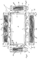
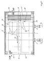
- the device 1 consists of FIGS. 1 to 5 a narrow, circumferential frame 2 a of a housing 2, the itself from a total of two longitudinal frame sides 3, 4 and two narrow frame sides 5, 6 composed.
- the frame 2a can of course also be triangular, square or polygonal.
- the frame sides 3, 4, 5, 6 are either over angles screwed together, glued together or welded together, which is irrelevant to the present invention.
- At the bottom Longitudinal side 4 are two waterproof sockets 7, 8 arranged, one of which with an electric Data supply line and the other with an electrical To couple power supply line is.
- the width B of the invention Device 1 can only be up to about 35 mm, because Consequently, in the consequent small interior 2b accumulate much faster amounts of heat.
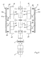
- the interior 2b of Housing 2 (see Fig. 6) is dashed in the upper part of the housing 2 framed as a block symbol of the control computer 11 and in the lower part of the housing 2 also a dashed as a block symbol framed power supply 12 indicated.
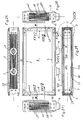
- Also located in the Interior 2b of the housing 2 either directly with the two transparent discs 9, 10 glued to the outside or with these are not glued in the same size as the transparent one Slices 9, 10 grid-shaped in modular construction composite Light emitting diodes, which the LED displays 13, 14 (see Figures 10 and 11) form.
- the LED displays 13, 14 see Figures 10 and 11
- the control computer 11, the power supply 12 and the LED displays 13, 14 are traversed by electricity, which leads to a corresponding heat development leads.
- the Device 1 usually elevated perpendicular to the bottom surface or suspended in winter and spring months Sunbeams shallow above the horizon of stroking sun perpendicular or nearly perpendicular to the transparent Slices 9, 10.
- the sun is in the Summer months relatively high above the surface, that is above the upper frame side 3 of FIG. 1 of the device 1.
- the transparent ones Slices 9, 10 turns the UV light into long-wave infrared light converted, which leads to a temperature increase in the Interior 2b of the housing 2 can lead to 70 ° C.
- control computer 11 is at one Support plate 15 and the power supply 12 on another Bracket plate 16 attached.
- On these support plates 15, 16 are also the support plates 13b, 14b of the LED displays 13, 14th attached.
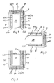
- the upper support plates 15 are shown in Figures 6 to 11 to the three sides 18, 19, 20 and the lower support plates 16 also on three sides, namely 21, 22 and 23 brinkantet. These upturned ends are made with three sides 3-6 of the likewise Aluminum or copper existing frame 2 a of the housing. 2 thermally conductively coupled, as most clearly shown in FIG. 6 can be removed.
- the mediationkanteten Ends 18-20 of the housing 2 overhead mounting plates 15th on the frame sides 5, 3, 6, whereas in the lower part of Housing 2 arranged Colourkanteten ends 21 to 23 of the Support plates 16 on the frame sides 5, 4, 6 abut.
- bent ends 18-23 of the support plates 15, 16 lie on the insides of the frame sides 3-6 on a general denoted by 24 thermal paste or a bathleitgel in thermally conductive contact, thereby increasing the heat transfer mitigating air gaps are prevented.
- the facing surfaces namely the Interior surfaces of the frame pages 3-6 on the one hand and with them contacting surfaces of the folded ends 18-23 on the other hand, with zigzag-shaped ribs in cross-section provided that interlock interlocking form-fitting.
- the cooling side 27 on the one hand and the adjacent réellekanteten ends 18-23 on the other hand and between the Warm side 29 and the adjacent insides of the Frame sides 3-6 is advantageous for avoiding air gaps ever a thermal paste or a townleitgel 24 is arranged.
- thermal compound 24 can not only air gaps avoided, but also a very effective heat transfer be achieved.
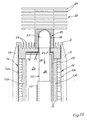
- a second embodiment of an additional cooling of Interior 2b of the housing 2 is in Figures 18 to 20 in the form a heat pipe (cooling tube) 30 shown.
- Everybody is Support plate 15, 16 and / or support plate 13 b, 14 b with the Evaporator section 31 of at least one heat pipe (cooling pipe) coupled thermally conductive.
- each heat Pipe 30 is either totally or partially with a frame side, here the frame side 3 of the housing 2, coupled thermally conductively and / or with a guided by this frame side 3 ribbed Plate member 33 with large heat transfer surface 34th thermally conductive connected.
- the coupling takes place in the present case, as most clearly shown in Fig. 20, by means of a Screw connection 35, or in other words, the capacitor part 32nd the Heat Pipe 30 is with an external thread 36 and the Plate member 33 with the large heat transfer surface 34 with a blind bore provided with internal thread 37, on which under Interposition of a thermally conductive paste (not shown here) the plate member 33 is screwed firmly.
- the plate member 33 with its large Heat transfer surface 34 is from the outside air as secondary coolant flows around, creating a direct Heat dissipation from the capacitor part 32 takes place. Consequently drips the condensed primary coolant in the interior 38 of the Heat Pipe 30 in the direction of arrow 39 under its gravity down in the evaporator part 31 back, in which the Evaporation process starts again. Because with one Evaporation process via a corresponding primary coolant low boiling point, for example methanol, Dichloromethane or chloroform, a significantly larger amount of heat than can be dissipated with any liquid coolant proves This type of extra heat dissipation is considered extreme effective and also without any additional power consumption.
- the evaporator parts 31 of the heat pipes 30 are under Interposition of a thermally conductive paste in holder pockets 40th the support plates 15, 16 are arranged.
- a third embodiment of an additional Cooling device in the interior 2b of the housing 2 is in the Figures 21 to 29 shown.
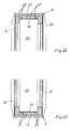
- a radial fan 41 (see Fig. 21) arranged and in itself known manner at least two opposite frame sides, here the frame sides 5, 6 (see Figures 24, 27 and 28), with at least one opening 42 provided by a grid 43 with covered with a nonwoven composite 44 which is waterproof, but is permeable to air.
- the power supply to the Electric motor that drives the radial fan 41 also advantageous as a function of the temperature in the interior 2b of Housing 2 of a temperature-controlled, not shown Switch on and off.
- FIGS. 22 and 23 and 29 illustrate the structure of the openings 42.
- FIG. 30 Another advantage of the device according to the invention shows the Fig. 30.
- the interior 2b can be a fully graphic Display surface 13, 14 used on both sides of the device 1 become.
- the graphics 46 to get high contrast, before the additional heat dissipation and thus an even more effective Cooling in the interior 2b when connecting the Peltier element 28, of the centrifugal fan 41 or by the efficiency of the heat pipes 30 used, are advantageously the outer surfaces 9a, 10a of transparent panes 9, 10 made of glass or acrylic resin, with a sprayed or painted two-component glass enamel Mistake.
- This two-component glass varnish has not only a higher-contrast reproduction of the graphic 46 result, but in a surprising way, it also exerts a heat-insulating effect regarding the UV rays of the sun and their Penetration force out. Thus, with the spraying of the Two-component glass paint also has a heat-insulating effect connected.
- the core of the invention is on the one hand in the permanent and active cooling by heat conduction and radiation over the réellekanteten ends 18-23 of the support plates 15, 16 and / or the support plates 13b, 14b to see. It is understood that Of course, the support plates 13b, 14b for the LED modules 13a, 14a are provided with studieskanteten ends can. This not only the heat transfer surface, but also the heat absorption capacity of the Support plates 13b, 14b and the support plates 15, 16 formed Unity plates 17 increased.
- the further essence of the invention is the optional (Radial fan 41 or Peltier element 28) or automatic Switching (heat pipe 30) of an additional cooling device. All additional cooling devices 28, 30, 41, which also can be combined with each other, as well as the Wegkanteten Ends 18-23 of mounting plates 15, 16 or Carrier plates 13b, 14b can easily be with each other Housing also find use. That's why it comes not in the specific type or assembly in this invention of the housing 2 of the device 1.
Landscapes
- Physics & Mathematics (AREA)
- General Physics & Mathematics (AREA)
- Engineering & Computer Science (AREA)
- Theoretical Computer Science (AREA)
- Cooling Or The Like Of Electrical Apparatus (AREA)
- Devices For Indicating Variable Information By Combining Individual Elements (AREA)
- Illuminated Signs And Luminous Advertising (AREA)
Abstract
Description
- Vorrichtung
- 1
- Gehäuse
- 2
- Rahmen des Gehäuses 2
- 2a
- Innenraum des Gehäuses 2
- 2b
- Rahmenseiten
- 3, 4, 5, 6
- Steckdosen
- 7, 8
- transparente Scheiben
- 9, 10
- Außenfläche der Scheiben 9, 10
- 9a, 10a
- Steuerrechner
- 11
- Netzteil
- 12
- LED-Anzeigen
- 13, 14
- LED-Module
- 13a, 14a
- Trägerplatten
- 13b, 14b
- Halterungsplatten
- 15, 16
- Einheitsplatte
- 17
- aufgekantete Enden
- 18-23
- Wärmeleitpaste
- 24
- Berippung
- 25
- Gewindebolzen
- 26
- Kühlseite
- 27
- Peltierelement
- 28
- Warmseite
- 29
- Heat Pipe
- 30
- Verdampferteil
- 31
- Kondensatorteil
- 32
- Plattenelement
- 33
- Wärmeübertragungsfläche
- 34
- Verschraubung
- 35
- Außengewinde
- 36
- Innengewinde
- 37
- Innenraum der Heat Pipe
- 38
- Pfeil
- 39
- Halterungstasche
- 40
- Radiallüfter
- 41
- Öffnung
- 42
- Gitter
- 43
- Vliesverbundstoff
- 44
- Doppelpfeil
- 45
- Graphik
- 46
- Gehäusebreite
- B
Claims (16)
- Vorrichtung mit dynamischer LED-Anzeige für den Außenoder Innenbereich mit einem Gehäuse mit einem umlaufenden Metallrahmen sowie mit einseitiger oder beidseitiger LED-Anzeige mit einem darin angeordneten Steuerrechner und Netzteil, wobei die LED-Dioden auf einer Trägerplatte und der Steuerrechner und das Netzteil auf einer Halterungsplatte angeordnet sind, dadurch gekennzeichnet, daß die Trägerplatte (13b, 14b) und die Halterungsplatte (15, 16) aus Aluminium oder Kupfer bestehen, die Halterungsplatte (15, 16) und/oder die Trägerplatte (13b, 14b) mit mindestens einem aufgekanteten Ende (18-23) versehen ist und dieses aufgekantete Ende (18-23) mit mindestens einer Seite (3-6) des gleichfalls aus Aluminium oder Kupfer bestehenden Rahmens (2a) des Gehäuses (2) wärmeleitend gekoppelt ist.
- Vorrichtung nach Anspruch 1, dadurch gekennzeichnet, daß die Halterungsplatte in zwei Halterungsplatten (15, 16) aufgeteilt ist, von denen die eine (16) das Netzteil (12) und die andere (15) den Steuerrechner (11) trägt.
- Vorrichtung nach Anspruch 1 oder 2, dadurch gekennzeichnet, daß mit der oder den Halterungsplatten (15, 16) die aus einer Aluminiumlegierung oder Kupfer bestehenden Trägerplatten ( 13b, 14b) von LED-Modulen (13a, 14a) wärmeleitend verbunden sind.
- Vorrichtung nach einem der Ansprüche 1 bis 3, dadurch gekennzeichnet, daß bei einer zweiseitigen LED-Anzeige (13, 14) die eine Trägerplatte (13b) mit der das Netzteil (12) halternden Halterungsplatte (16) und die andere Trägerplatte (14b) mit der den Steuerrechner (11) halternden Halterungsplatte (15) wärmeleitend verbunden ist.
- Vorrichtung nach einem der Ansprüche 1 bis 4, dadurch gekennzeichnet, daß jede Halterungsplatte (15, 16) und/oder jede Trägerplatte (13b, 14b) mit drei aufgekanteten Enden (18-23) versehen ist und diese mit den drei zugeordneten Rahmenseiten (3-6) des Rahmens (2a) des Gehäuses (2) über eine Wärmeleitpaste (24) oder ein Wärmeleitgel wärmeübertragend gekoppelt sind.
- Vorrichtung nach einem der Ansprüche 1 bis 5, dadurch gekennzeichnet, daß jede Halterungsplatte (15, 16) mit der ihr zugeordneten Trägerplatte (13b, 14b) der LED-Module (13a, 14a) über Schrauben (26) und Muttern (26a) zu einer Einheitsplatte (17) wärmeleitend verbunden ist.
- Vorrichtung nach einem der Ansprüche 1 bis 6, dadurch gekennzeichnet, daß jede Halterungsplatte (15, 16) und/oder Trägerplatte ( 13b, 14b) mit dem Verdampferteil (31) von mindestens einer Heat Pipe (Kühlrohr) (30) wärmeleitend gekoppelt ist, dessen Kondensatorteil (32) entweder ganz oder teilweise mit einer Rahmenseite (3) des Gehäuses (2) und/oder mit einem durch diese Rahmenseite (3) geführtes beripptes Plattenelement (33) mit großer Wärmeübertragungsfläche (34) wärmeleitend gekoppelt ist.
- Vorrichtung nach einem der Ansprüche 1 bis 6, dadurch gekennzeichnet, daß jede Halterungsplatte (15, 16) und/oder Trägerplatte (13b, 14b) mit der Kühlseite (27) mindestens eines Peltierelementes (28) verbunden ist, dessen Warmseite (29) mit mindestens einer metallischen Rahmenseite (3-6) des Gehäuses (2) in wärmeleitender Verbindung steht.
- Vorrichtung nach einem der Ansprüche 1 bis 6, dadurch gekennzeichnet, daß im Innenraum des Gehäuses zwischen den Halterungsplatten (15, 16) ein Radiallüfter (41) angeordnet ist und in an sich bekannter Weise der Rahmen (2a) an zwei gegenüberliegenden Rahmenseiten (5, 6) mit mindestens einer Öffnung (42) versehen ist, die von einem Vliesverbundstoff (44) wasserdicht, aber luftdurchlässig abgedeckt ist.
- Vorrichtung nach Anspruch 9, dadurch gekennzeichnet, daß die dem Luftstrom des Radiallüfters (41) ausgesetzten Flächen der Halterungsplatte (15, 16) und/oder der Trägerplatte (13b, 14b) mit zusätzlichen Rippen, Stiften, Plättchen oder Haken zur Vergrößerung der Wärmeübertragungsfläche versehen sind.
- Vorrichtung nach einem der Ansprüche 8 bis 10, dadurch gekennzeichnet, daß die Stromzufuhr zum Peltierelement (28) und zum Radiallüfter (41) in Abhängigkeit von der Temperatur im Innenraum (2b) des Gehäuses (2) von einem temperaturgesteuerten Schalter zu- und abschaltbar ist.
- Vorrichtung nach einem der Ansprüche 1 bis 11, dadurch gekennzeichnet, daß die aufgekanteten Enden (18-23) der Halterungsplatten (15, 16) und/oder der Trägerplatten (13b, 14b) über eine Wärmeleitpaste (24) mit den metallischen Rahmenseiten (3-6) in wärmeleitendem Kontakt stehen.
- Vorrichtung nach einem der Ansprüche 1 bis 12, dadurch gekennzeichnet, daß sämtliche metallischen Rahmenseiten (3-6) an ihrer Außenseite zur Vergrößerung ihrer Wärmeübertragungsfläche mit Rippen (25) versehen sind.
- Vorrichtung nach einem der Ansprüche 1 bis 13, dadurch gekennzeichnet, daß die LED-Module (13a, 14a) sowie ihre Steuerhalbleiter mittels einer wärmeleitenden, doppelseitig klebenden Folie mit einer Platine auf aus Aluminium oder Kupfer bestehenden Kühlkörpern befestigt sind, die über in letztere eingelassene und daran gehalterte Gewindebolzen (26) eine Trägerplatte (13b, 14b) bilden, die mit der zugeordneten Halterungsplatte (15 oder 16) zu einer kompakten Einheitsplatte (13b, 15; 14b, 16) verschraubt sind.
- Vorrichtung nach Anspruch 14, dadurch gekennzeichnet, daß zwischen der Trägerplatte ( 13b, 14b) und der Halterungsplatte (15, 16) eine wärmeleitende Paste (24) oder ein Wärmeleitgel zur Erhöhung der Wärmeübertragung angeordnet ist.
- Vorrichtung nach einem der Ansprüche 1 bis 15, dadurch gekennzeichnet, daß die Anzeigeflächen (13, 14) der LED-Module (13a, 14a) von transparenten Scheiben (9, 10) aus Glas oder Acrylharz abgedeckt sind, die an ihrer Außenfläche (9a, 10a) mit einem Zweikomponenten-Glaslack, einer aufgedampften Glaslackschicht oder mit einer Glaslackfolie versehen sind.
Applications Claiming Priority (2)
| Application Number | Priority Date | Filing Date | Title |
|---|---|---|---|
| DE10339412A DE10339412B4 (de) | 2003-08-27 | 2003-08-27 | Vorrichtung mit dynamischer LED-Anzeige sowie mit einer Einrichtung zum Wärmeabtransport aus dem Innenraum eines Gehäuses in die Umgebung |
| DE10339412 | 2003-08-27 |
Publications (2)
| Publication Number | Publication Date |
|---|---|
| EP1510993A2 true EP1510993A2 (de) | 2005-03-02 |
| EP1510993A3 EP1510993A3 (de) | 2006-03-15 |
Family
ID=34089211
Family Applications (1)
| Application Number | Title | Priority Date | Filing Date |
|---|---|---|---|
| EP04019573A Withdrawn EP1510993A3 (de) | 2003-08-27 | 2004-08-18 | Vorrichtung mit dynamischer LED-Anzeige |
Country Status (2)
| Country | Link |
|---|---|
| EP (1) | EP1510993A3 (de) |
| DE (1) | DE10339412B4 (de) |
Cited By (1)
| Publication number | Priority date | Publication date | Assignee | Title |
|---|---|---|---|---|
| CN114973958A (zh) * | 2022-06-02 | 2022-08-30 | 广东森克电子有限公司 | 一种多功能触摸一体机 |
Families Citing this family (2)
| Publication number | Priority date | Publication date | Assignee | Title |
|---|---|---|---|---|
| DE102008054233A1 (de) | 2008-10-31 | 2010-05-06 | Osram Opto Semiconductors Gmbh | Leuchtmodul |
| DE102011018238A1 (de) * | 2011-04-19 | 2012-10-25 | Ackutech AG | Leuchtrahmenvorrichtung |
Family Cites Families (6)
| Publication number | Priority date | Publication date | Assignee | Title |
|---|---|---|---|---|
| JP2818984B2 (ja) * | 1992-03-04 | 1998-10-30 | 株式会社 ケー・シー・シー・商会 | モザイク式パネル用照光表示装置 |
| DE29819742U1 (de) * | 1998-10-01 | 1999-01-07 | Lumino Licht Elektronik GmbH, 47799 Krefeld | Einrichtung zur Anzeige von alpha-nummerischen und/oder Bildzeichen |
| WO2002061714A2 (de) * | 2001-02-02 | 2002-08-08 | Sunamic Visualisierung Und Netzwerk Gmbh | Modul für grafische anzeigen im freien |
| TW510532U (en) * | 2001-07-25 | 2002-11-11 | Wen-Chen Wei | Flexible heat tube structure |
| DE10207264C1 (de) * | 2002-02-21 | 2003-06-26 | Line Elektro Electronic Gmbh E | Vorrichtung mit dynamischer LED-Anzeige für den Außenbereich des öffentlichen Personennahverkehrs |
| DE20313263U1 (de) * | 2003-08-27 | 2003-11-13 | provi GmbH, 09661 Hainichen | Vorrichtung mit dynamischer LED-Anzeige, insbesondere für den Außenbereich des öffentlichen Personennahverkehr |
-
2003
- 2003-08-27 DE DE10339412A patent/DE10339412B4/de not_active Expired - Fee Related
-
2004
- 2004-08-18 EP EP04019573A patent/EP1510993A3/de not_active Withdrawn
Cited By (1)
| Publication number | Priority date | Publication date | Assignee | Title |
|---|---|---|---|---|
| CN114973958A (zh) * | 2022-06-02 | 2022-08-30 | 广东森克电子有限公司 | 一种多功能触摸一体机 |
Also Published As
| Publication number | Publication date |
|---|---|
| DE10339412A1 (de) | 2005-04-07 |
| EP1510993A3 (de) | 2006-03-15 |
| DE10339412B4 (de) | 2005-11-10 |
Similar Documents
| Publication | Publication Date | Title |
|---|---|---|
| DE2806337C2 (de) | Sonnenkollektoranlage zur unmittelbaren Umwandlung der zugeführten Wärmeenergie in elektrische Energie | |
| EP1338451A2 (de) | Elektrische Luftheizungsvorrichtung insbesondere für ein Kraftfahrzeug | |
| EP2139046A1 (de) | Fotovoltaisches modul | |
| DE102014017161A1 (de) | Eine Motorantriebseinheit mit einem Kühlkörper, der Kühlschmierstofftropfen ableitet | |
| EP1649736B1 (de) | Kühlvorrichtung für ein elektronisches bauelement, insbesondere für einen mikroprozessor | |
| AT505154B1 (de) | Optische signaleinrichtung | |
| DE102020104542A1 (de) | Photovoltaikeinheit und Solaranordnung | |
| DE10251446A1 (de) | Kühlanordnung für lichtbündelnde Photovoltaik-Anlagen | |
| DE69506710T2 (de) | Sonnenkollektor | |
| DE3735985A1 (de) | Waermeleitender modul fuer gedruckte schaltungsplattenanordnung | |
| EP2376829B1 (de) | Led-basiertes beleuchtungssystem | |
| AT506684A1 (de) | Photovoltaik-modul | |
| DE69405504T2 (de) | Kühlgerät mit elektronischer Kühlung | |
| DE10339412B4 (de) | Vorrichtung mit dynamischer LED-Anzeige sowie mit einer Einrichtung zum Wärmeabtransport aus dem Innenraum eines Gehäuses in die Umgebung | |
| DE102011078300A1 (de) | Solaranlage mit einem Sonnenkollektor und einem fotovoltaischen oder thermoelektrischen Wandler | |
| DE102008022000A1 (de) | Gehäuse | |
| DE20313264U1 (de) | Vorrichtung mit dynamischer LED-Anzeige sowie mit einer Einrichtung zum Wärmeabtransport aus dem Innenraum eines Gehäuses in die Umgebung | |
| DE29908205U1 (de) | Vorrichtung zur Umwandlung von Solarenergie in elektrische Energie und Einrichtung an einem Gebäude mit einer derartigen Vorrichtung | |
| DE202009017596U1 (de) | Kühlsystem für LED-Hochleistungsstraßenbeleuchtung | |
| DE29810238U1 (de) | Solarzellenanordnung | |
| DE102009060725A1 (de) | Kühlsystem für die LED-Hochleistungsstraßenbeleuchtung | |
| DE10149620A1 (de) | Strom-Wärme-Solar-Kollektor | |
| DE202007000300U1 (de) | Konzentrator-Photovoltaik-Vorrichtung mit zusätzlicher thermischer Nutzung sowie damit versehene Anlage | |
| DE19747325A1 (de) | Solarzellenmodule mit integrierter Kühlung der Solarzellen | |
| DE102021113569A1 (de) | Led-lampe mit eingebauter spannungsversorgung |
Legal Events
| Date | Code | Title | Description |
|---|---|---|---|
| PUAI | Public reference made under article 153(3) epc to a published international application that has entered the european phase |
Free format text: ORIGINAL CODE: 0009012 |
|
| AK | Designated contracting states |
Kind code of ref document: A2 Designated state(s): AT BE BG CH CY CZ DE DK EE ES FI FR GB GR HU IE IT LI LU MC NL PL PT RO SE SI SK TR |
|
| AX | Request for extension of the european patent |
Extension state: AL HR LT LV MK |
|
| PUAL | Search report despatched |
Free format text: ORIGINAL CODE: 0009013 |
|
| RIC1 | Information provided on ipc code assigned before grant |
Ipc: G09F 13/22 20060101ALI20060102BHEP Ipc: G09F 13/04 20060101ALI20060102BHEP Ipc: G09F 9/33 20060101AFI20041223BHEP |
|
| AK | Designated contracting states |
Kind code of ref document: A3 Designated state(s): AT BE BG CH CY CZ DE DK EE ES FI FR GB GR HU IE IT LI LU MC NL PL PT RO SE SI SK TR |
|
| AX | Request for extension of the european patent |
Extension state: AL HR LT LV MK |
|
| AKX | Designation fees paid |
Designated state(s): AT BE BG CH CY CZ DE DK EE ES FI FR GB GR HU IE IT LI LU MC NL PL PT RO SE SI SK TR |
|
| 17P | Request for examination filed |
Effective date: 20060912 |
|
| 19U | Interruption of proceedings before grant |
Effective date: 20080131 |
|
| 19W | Proceedings resumed before grant after interruption of proceedings |
Effective date: 20081201 |
|
| RAP1 | Party data changed (applicant data changed or rights of an application transferred) |
Owner name: ISOTRONIC-SYSTEMS GMBH |
|
| STAA | Information on the status of an ep patent application or granted ep patent |
Free format text: STATUS: THE APPLICATION IS DEEMED TO BE WITHDRAWN |
|
| 18D | Application deemed to be withdrawn |
Effective date: 20090602 |