EP1510753A2 - Beleuchtungseinrichtung für Fahrzeuge - Google Patents
Beleuchtungseinrichtung für Fahrzeuge Download PDFInfo
- Publication number
- EP1510753A2 EP1510753A2 EP04019665A EP04019665A EP1510753A2 EP 1510753 A2 EP1510753 A2 EP 1510753A2 EP 04019665 A EP04019665 A EP 04019665A EP 04019665 A EP04019665 A EP 04019665A EP 1510753 A2 EP1510753 A2 EP 1510753A2
- Authority
- EP
- European Patent Office
- Prior art keywords
- light
- lighting device
- lens
- reflector
- matting
- Prior art date
- Legal status (The legal status is an assumption and is not a legal conclusion. Google has not performed a legal analysis and makes no representation as to the accuracy of the status listed.)
- Withdrawn
Links
- 230000003287 optical effect Effects 0.000 claims abstract description 17
- 239000000463 material Substances 0.000 claims description 11
- 238000005286 illumination Methods 0.000 claims description 6
- 230000003746 surface roughness Effects 0.000 claims description 4
- 238000005530 etching Methods 0.000 claims description 2
- 239000012780 transparent material Substances 0.000 claims 1
- 238000002347 injection Methods 0.000 description 4
- 239000007924 injection Substances 0.000 description 4
- 238000000149 argon plasma sintering Methods 0.000 description 3
- 239000006185 dispersion Substances 0.000 description 2
- 238000004519 manufacturing process Methods 0.000 description 2
- 206010037867 Rash macular Diseases 0.000 description 1
- 230000015556 catabolic process Effects 0.000 description 1
- 230000000295 complement effect Effects 0.000 description 1
- 238000011109 contamination Methods 0.000 description 1
- 230000003247 decreasing effect Effects 0.000 description 1
- 238000002594 fluoroscopy Methods 0.000 description 1
- 238000001746 injection moulding Methods 0.000 description 1
- 230000000149 penetrating effect Effects 0.000 description 1
- 230000005855 radiation Effects 0.000 description 1
Images

Classifications
-
- F—MECHANICAL ENGINEERING; LIGHTING; HEATING; WEAPONS; BLASTING
- F21—LIGHTING
- F21S—NON-PORTABLE LIGHTING DEVICES; SYSTEMS THEREOF; VEHICLE LIGHTING DEVICES SPECIALLY ADAPTED FOR VEHICLE EXTERIORS
- F21S43/00—Signalling devices specially adapted for vehicle exteriors, e.g. brake lamps, direction indicator lights or reversing lights
- F21S43/40—Signalling devices specially adapted for vehicle exteriors, e.g. brake lamps, direction indicator lights or reversing lights characterised by the combination of reflectors and refractors
-
- F—MECHANICAL ENGINEERING; LIGHTING; HEATING; WEAPONS; BLASTING
- F21—LIGHTING
- F21S—NON-PORTABLE LIGHTING DEVICES; SYSTEMS THEREOF; VEHICLE LIGHTING DEVICES SPECIALLY ADAPTED FOR VEHICLE EXTERIORS
- F21S41/00—Illuminating devices specially adapted for vehicle exteriors, e.g. headlamps
- F21S41/30—Illuminating devices specially adapted for vehicle exteriors, e.g. headlamps characterised by reflectors
- F21S41/37—Illuminating devices specially adapted for vehicle exteriors, e.g. headlamps characterised by reflectors characterised by their material, surface treatment or coatings
-
- F—MECHANICAL ENGINEERING; LIGHTING; HEATING; WEAPONS; BLASTING
- F21—LIGHTING
- F21S—NON-PORTABLE LIGHTING DEVICES; SYSTEMS THEREOF; VEHICLE LIGHTING DEVICES SPECIALLY ADAPTED FOR VEHICLE EXTERIORS
- F21S43/00—Signalling devices specially adapted for vehicle exteriors, e.g. brake lamps, direction indicator lights or reversing lights
- F21S43/30—Signalling devices specially adapted for vehicle exteriors, e.g. brake lamps, direction indicator lights or reversing lights characterised by reflectors
-
- F—MECHANICAL ENGINEERING; LIGHTING; HEATING; WEAPONS; BLASTING
- F21—LIGHTING
- F21S—NON-PORTABLE LIGHTING DEVICES; SYSTEMS THEREOF; VEHICLE LIGHTING DEVICES SPECIALLY ADAPTED FOR VEHICLE EXTERIORS
- F21S43/00—Signalling devices specially adapted for vehicle exteriors, e.g. brake lamps, direction indicator lights or reversing lights
- F21S43/20—Signalling devices specially adapted for vehicle exteriors, e.g. brake lamps, direction indicator lights or reversing lights characterised by refractors, transparent cover plates, light guides or filters
- F21S43/26—Refractors, transparent cover plates, light guides or filters not provided in groups F21S43/235 - F21S43/255
-
- F—MECHANICAL ENGINEERING; LIGHTING; HEATING; WEAPONS; BLASTING
- F21—LIGHTING
- F21V—FUNCTIONAL FEATURES OR DETAILS OF LIGHTING DEVICES OR SYSTEMS THEREOF; STRUCTURAL COMBINATIONS OF LIGHTING DEVICES WITH OTHER ARTICLES, NOT OTHERWISE PROVIDED FOR
- F21V7/00—Reflectors for light sources
- F21V7/22—Reflectors for light sources characterised by materials, surface treatments or coatings, e.g. dichroic reflectors
Definitions
- the invention relates to a lighting device for vehicles, in particular a Signal light, with at least one light source behind a luminaire chamber a translucent lens is arranged, and with at least one reflector for Bundling the light emitted by the light source.
- Such a signal light is known from DE 100 32 509 A1. It points as a light source an incandescent lamp, which is arranged in the focal point of a high-gloss reflector, the light emitted by the light source to a light beam with parallel Light rays bundles.
- the incandescent lamp and the reflector are behind a translucent Lens arranged, which has a translucent material in which light scattering inclusions are located. If the signal light is off, that is Luminaire inside through the lens not clearly visible. Thereby results in a homogeneous appearance of the signal light.
- This object is achieved in that the reflector and / or at least one of the Lamp facing side boundary wall of the lamp chamber a matting having.
- the light emitted by the light source is at the matting deflected in different directions, leaving it as a widened beam of light the translucent lens hits.
- parts of the bulb and / or of the reflector such as e.g. a filament, its holder and / or a socket breakthrough of the reflector, only very blurred on the lens.
- this is at a contours sharp picture of these parts occurring blotchy appearance of Lens, avoided.
- the light is in apparent unnecessarily redistributed. It has surprisingly been found that by these measures both on and off Condition of the lighting device a very uniform, homogeneous appearance the lighting device is made possible.
- the matting are formed by a surface roughness.
- a Such matting can cost in a plastic injection molded part without a additional manufacturing step already during the injection molding process on the surface of the injection molded part (reflector, side boundary wall of the luminaire chamber) be generated.
- the matting are formed by a color layer.
- a color layer which is preferably formed as a silvery matt finish is, can be a very uniform dispersion of the radiated from the bulb Reach the light towards the lens.
- the surface roughness a structure that a generated by etching surface structure and / or a Negative form of such a surface structure corresponds.
- the surface structure can then on an injection mold for the production of the reflector and / or the lamp chamber be generated in a simple manner by a surface area to be structured the injection mold is brought into contact with an etchant.
- the reflector has an optical grid on which the incident thereon Light in the position of use located lighting device in horizontal Direction is scattered.
- the legal requirements for the horizontal light distribution of the from the illumination device emitted light beam can then with large Precision be fulfilled.
- the optical grid can pillow-shaped and / or cylindrical Have optical elements. For compliance with legal requirements for Light distribution in the vertical direction extends the scattering of the translucent lens out.
- the optical grid has strip-shaped optical elements which when in use position lighting device in about vertical direction run.
- the reflector is then inexpensive to produce.
- the combination, consisting made of vertical cylinder optics, matting and translucent lens produces a very Homogeneous illumination, in which even with the light bulb on the picture a provided in the reflector socket hole for the light source on the Lens is almost completely laminated.
- a particularly uniform scattering of passing through the lens Light can be achieved by making the lens a translucent Has material in which are inclusions, as optical scattering elements are formed.
- the enclosing the inclusions translucent material has preferably has a first refractive index, wherein the optical scattering elements of a second translucent material with a second refractive index and preferably have a spherical shape.
- the inclusions can reach a size of 0.1 ⁇ m 100 microns have.
- the lighting means is at least partly by a translucent located between the lens and the light source Cap covered, wherein the cap has a matting and / or off a translucent material.
- a in Fig. 1 as a whole designated 1, designed as a signal light illumination device for vehicles has at least one bulb 2, which in a Luminaire chamber 3 is arranged behind a translucent lens 4.
- the lighting chamber 3 is formed in a lamp housing 5, which serves as a carrier part for the lighting means 2 and the lens 4 is used.
- a Reflector 6 for bundling the light emitted from the light source 2 in the direction of the lens 4 is arranged.
- the reflector 6 at the Rear side of the lamp chamber 3 is arranged and has an opening into which the as Incandescent lamp 2 is used.
- the luminaire chamber 3 is laterally bounded by side boundary walls 7. At the front is the lamp chamber 3 covered by the lens 4.
- the reflector 6 and the side boundary walls 7 have at their the bulbs. 2 facing surface areas in the drawing matting not shown on which the incident thereon, emitted by the light source 2 light in horizontal and vertical direction is scattered.
- This will be a contour sharp Figure in particular of the filament of the bulb 2, the filament holder and the socket breakdown of the reflector 6 on the translucent lens 4 and thus a spotty appearance of the lens 4 with the light bulb 2 is avoided.
- the reflector 6 has a vertical optics, the optical grid with a plurality of strip-shaped has optical elements, which at the light emitting means 2 facing surface of the reflector 6 approximately parallel to each other.
- Fig. 1 is clearly visible that the incident on the reflector 6 light beam is expanded in the reflection.
- the widening of the light beam is in horizontal direction greater than in the vertical direction.
- the lens 4 has a translucent first material with a first Refractive index, in which approximately spherical inclusions of a translucent second material with a second refractive index. At the inclusions this will be light passing through the lens 4 is scattered. It is even possible that the light rays as they pass through the lens 4 in succession to several Inclusions hit, causing even more uniform light scattering.
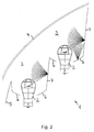
- the illumination device 1 has two Bulb 2 for different lighting functions on, for example a Flashing light and an additional rear light.
- the lamps 2 is in each case a reflector 6 with a associated with vertical optics.
- the bulbs 2 and the reflectors 6 are in horizontal Direction next to each other in a lamp chamber 3. This is through a translucent lens 4 covered, which is consistently on the bulbs. 2 extends.
- the reflectors 6 and the side boundary walls 7 of the lamp chamber 3rd each have a matting.
- Fig. 2 is based on three of the light source. 2 emitted light rays indicated schematically that the of the bulbs. 2 radiated light on the matting of the reflectors 6 and the side boundary walls 7 is scattered in the direction of the translucent lens 4.
Landscapes
- Engineering & Computer Science (AREA)
- General Engineering & Computer Science (AREA)
- Non-Portable Lighting Devices Or Systems Thereof (AREA)
Abstract
Description
- Fig. 1
- einen horizontalen Teillängsschnitt durch eine Signalleuchte, wobei der Strahlengang eines Teils des von dem Leuchtmittel abgestrahlten Lichts durch Lichtstrahlen markiert ist, und
- Fig. 2
- einen horizontalen Teillängsschnitt durch eine Signalleuchte für unterschiedliche Signallichtfunktionen, wobei der Strahlengang des von den Leuchtmittel jeweils abgestrahlten Lichts anhand von Lichtstrahlen beispielhaft markiert ist.
Claims (9)
- Beleuchtungseinrichtung (1) für Fahrzeuge, insbesondere Signalleuchte, mit mindestens einem Leuchtmittel (2), das in einer Leuchtenkammer (3) hinter einer transluzenten Lichtscheibe (4) angeordnet ist, und mit mindestens einem Reflektor (6) zum Bündeln des von dem Leuchtmittel (2) abgestrahlten Lichts, dadurch gekennzeichnet, dass der Reflektor (6) und/oder wenigstens eine dem Leuchtmittel (2) zugewandte Seitenbegrenzungswand (7) der Leuchtenkammer (3) eine Mattierung aufweist.
- Beleuchtungseinrichtung (1) nach Anspruch 1, dadurch gekennzeichnet, dass die Mattierung durch eine Oberflächenrauhigkeit gebildet sind.
- Beleuchtungseinrichtung (1) nach Anspruch 1 oder 2, dadurch gekennzeichnet, dass die Mattierung durch eine Farbschicht gebildet sind.
- Beleuchtungseinrichtung (1) nach einem der Ansprüche 1 bis 3, dass die Oberflächenrauhigkeit eine Struktur aufweist, die einer durch Ätzen erzeugten Oberflächenstruktur und/oder einer Negativform einer solchen Oberflächenstruktur entspricht.
- Beleuchtungseinrichtung (1) nach einem der Ansprüche 1 bis 4, dadurch gekennzeichnet, dass der Reflektor (6) ein Optikraster aufweist, an dem das darauf auftreffende Licht bei in Gebrauchsstellung befindlicher Beleuchtungseinrichtung in horizontaler Richtung gestreut wird.
- Beleuchtungseinrichtung (1) nach einem der Ansprüche 1 bis 5, dadurch gekennzeichnet, dass das Optikraster streifenförmige optische Elemente aufweist, die bei in Gebrauchsstellung befindlicher Beleuchtungseinrichtung in etwa vertikaler Richtung verlaufen.
- Beleuchtungseinrichtung (1) nach einem der Ansprüche 1 bis 6, dadurch gekennzeichnet, dass die Lichtscheibe (4) einen lichtdurchlässigen Werkstoff aufweist, in dem sich Einschlüsse befinden, die als optische Streuelemente ausgebildet sind.
- Beleuchtungseinrichtung (1) nach einem der Ansprüche 1 bis 7, dadurch gekennzeichnet, dass der die Einschlüsse umschließende lichtdurchlässige Werkstoff eine erste Brechzahl aufweist, und dass die optischen Streuelemente aus einem zweiten lichtdurchlässigen Werkstoff mit einer zweiten Brechzahl bestehen und vorzugsweise eine sphärische Form aufweisen.
- Beleuchtungseinrichtung (1) nach einem der Ansprüche 1 bis 8, dadurch gekennzeichnet, dass das Leuchtmittel (2) zumindest teilweise von einer zwischen der Lichtscheibe (4) und dem Leuchtmittel (2) befindlichen lichtdurchlässigen Kappe abgedeckt ist, und dass die Kappe eine Mattierung aufweist und/oder aus einem transluzenten Werkstoff besteht.
Applications Claiming Priority (2)
| Application Number | Priority Date | Filing Date | Title |
|---|---|---|---|
| DE10338785A DE10338785A1 (de) | 2003-08-23 | 2003-08-23 | Beleuchtungseinrichtung für Fahrzeuge |
| DE10338785 | 2003-08-23 |
Publications (2)
| Publication Number | Publication Date |
|---|---|
| EP1510753A2 true EP1510753A2 (de) | 2005-03-02 |
| EP1510753A3 EP1510753A3 (de) | 2007-12-19 |
Family
ID=34089178
Family Applications (1)
| Application Number | Title | Priority Date | Filing Date |
|---|---|---|---|
| EP04019665A Withdrawn EP1510753A3 (de) | 2003-08-23 | 2004-08-19 | Beleuchtungseinrichtung für Fahrzeuge |
Country Status (2)
| Country | Link |
|---|---|
| EP (1) | EP1510753A3 (de) |
| DE (1) | DE10338785A1 (de) |
Citations (1)
| Publication number | Priority date | Publication date | Assignee | Title |
|---|---|---|---|---|
| DE10032509A1 (de) | 1999-07-06 | 2001-02-08 | Valeo Vision | Beleuchtungs- oder Signalvorrichtung für Kraftfahrzeuge mit verbesserten Mitteln zur Lichtstreuung |
Family Cites Families (14)
| Publication number | Priority date | Publication date | Assignee | Title |
|---|---|---|---|---|
| BE373956A (de) * | ||||
| US1751934A (en) * | 1927-11-03 | 1930-03-25 | Egarsol Glareless Reflector Co | Antiglare reflector |
| DE3111701A1 (de) * | 1981-03-25 | 1982-10-07 | Trilux-Lenze Gmbh + Co Kg, 5760 Arnsberg | "leuchte mit einer kolbenfoermigen gasentladungslampe" |
| GB2108256B (en) * | 1981-10-09 | 1985-09-11 | Wipac Dev Limited | Vehicle lamp |
| FR2516203B1 (fr) * | 1981-11-12 | 1986-03-14 | Cibie Projecteurs | Projecteur de vehicule automobile |
| FR2546607B1 (fr) * | 1983-05-25 | 1986-03-14 | Cibie Projecteurs | Perfectionnements aux feux de vehicules automobiles |
| FR2695362B1 (fr) * | 1992-09-09 | 1994-12-02 | Valeo Vision | Feu de signalisation à visibilité latérale améliorée pour véhicule automobile. |
| FR2704624B1 (fr) * | 1993-04-28 | 1995-07-21 | Valeo Vision | Projecteur a eblouissement reduit pour vehicule automobile. |
| DE19619501C1 (de) * | 1996-05-14 | 1997-12-18 | Ralf Dr Kinkeldey | Leuchte zur indirekten Ausleuchtung eines Raumes |
| DE19704467B4 (de) * | 1997-02-06 | 2006-07-20 | Automotive Lighting Reutlingen Gmbh | Fahrzeug-Scheinwerfer |
| US6012830A (en) * | 1998-06-23 | 2000-01-11 | Valeo Sylvania L.L.C. | Light shield for a vehicle headlamp |
| DE29823027U1 (de) * | 1998-12-24 | 1999-03-25 | Johann & Konen GmbH & Co, 53229 Bonn | Fahrzeugrückleuchte |
| FR2819040B1 (fr) * | 2001-01-02 | 2003-09-12 | Valeo Vision | Composant d'optique ou de style pour dispositif d'eclairage ou de signalisation pour vehicule automobile |
| JP3953764B2 (ja) * | 2001-09-20 | 2007-08-08 | 株式会社小糸製作所 | 車両用灯具 |
-
2003
- 2003-08-23 DE DE10338785A patent/DE10338785A1/de not_active Withdrawn
-
2004
- 2004-08-19 EP EP04019665A patent/EP1510753A3/de not_active Withdrawn
Patent Citations (1)
| Publication number | Priority date | Publication date | Assignee | Title |
|---|---|---|---|---|
| DE10032509A1 (de) | 1999-07-06 | 2001-02-08 | Valeo Vision | Beleuchtungs- oder Signalvorrichtung für Kraftfahrzeuge mit verbesserten Mitteln zur Lichtstreuung |
Also Published As
| Publication number | Publication date |
|---|---|
| DE10338785A1 (de) | 2005-03-17 |
| EP1510753A3 (de) | 2007-12-19 |
Similar Documents
| Publication | Publication Date | Title |
|---|---|---|
| DE102006044019B4 (de) | Reflektorstrahler | |
| DE102008048765B4 (de) | Beleuchtungsvorrichtung für Kraftfahrzeuge | |
| DE10311072A1 (de) | Fahrzeugleuchte mit LED-Lichtquellen | |
| DE102016125887A1 (de) | Lichtmodul für Kraftfahrzeugscheinwerfer | |
| AT16685U1 (de) | Direktstrahlende LED-Leuchte mit Entblendungsoptik | |
| DE102011085314B3 (de) | Lichtmodul einer Beleuchtungseinrichtung eines Kraftfahrzeugs | |
| DE102014211874A1 (de) | Beleuchtungseinrichtung eines Kraftfahrzeugs | |
| DE102022118948A1 (de) | Fahrzeugleuchte | |
| DE69714546T2 (de) | Signalleuchte, insbesondere für Fahrzeuge, mit verbessertem Aussehen im ausgeschaltetem Zustand | |
| DE102014213824B4 (de) | Fahrzeugleuchte | |
| DE102016118717A1 (de) | Beleuchtungsvorrichtung für Fahrzeuge | |
| DE19646042B4 (de) | Fahrzeug-Beleuchtungseinrichtung | |
| DE20211305U1 (de) | Beleuchtungseinrichtung für ein Kraftfahrzeug mit mehreren Leuchteinheiten | |
| DE102008046748B4 (de) | Beleuchtungseinrichtung für ein Kraftfahrzeug | |
| EP1380469A2 (de) | Beleuchtungseinrichtung für Fahrzeuge | |
| DE102011014113A1 (de) | Transparente Optik einer Beleuchtungseinrichtung eines Kraftfahrzeugs | |
| DE102018220623A1 (de) | Leuchtenanordnung für ein Fahrzeug | |
| DE102011051541B4 (de) | Beleuchtungsvorrichtung für Fahrzeuge | |
| DE112019004405T5 (de) | Optisches Element einer Fahrzeugleuchte, Fahrzeugleuchtenmodul, Fahrzeug-Scheinwerfer und Fahrzeug | |
| DE102015204735A1 (de) | Lichtleiterelement einer Kraftfahrzeug-Beleuchtungseinrichtung und Kraftfahrzeug-Beleuchtungseinrichtung mit einem solchen Lichtleiterelement | |
| DE102015202541A1 (de) | Kraftfahrzeugleuchte | |
| DE19831004A1 (de) | LED-Leuchte für ein Kraftfahrzeug | |
| DE602004010962T2 (de) | Signalleuchte für Fahrzeuge | |
| DE102016101345A1 (de) | Leuchte mit pyramidenförmiger oder kegelförmiger Abdeckung | |
| DE4420889B4 (de) | Beleuchtungsvorrichtung für Fahrzeuge |
Legal Events
| Date | Code | Title | Description |
|---|---|---|---|
| PUAI | Public reference made under article 153(3) epc to a published international application that has entered the european phase |
Free format text: ORIGINAL CODE: 0009012 |
|
| AK | Designated contracting states |
Kind code of ref document: A2 Designated state(s): AT BE BG CH CY CZ DE DK EE ES FI FR GB GR HU IE IT LI LU MC NL PL PT RO SE SI SK TR |
|
| AX | Request for extension of the european patent |
Extension state: AL HR LT LV MK |
|
| PUAL | Search report despatched |
Free format text: ORIGINAL CODE: 0009013 |
|
| AK | Designated contracting states |
Kind code of ref document: A3 Designated state(s): AT BE BG CH CY CZ DE DK EE ES FI FR GB GR HU IE IT LI LU MC NL PL PT RO SE SI SK TR |
|
| AX | Request for extension of the european patent |
Extension state: AL HR LT LV MK |
|
| 17P | Request for examination filed |
Effective date: 20080529 |
|
| AKX | Designation fees paid |
Designated state(s): AT BE BG CH CY CZ DE DK EE ES FI FR GB GR HU IE IT LI LU MC NL PL PT RO SE SI SK TR |
|
| 17Q | First examination report despatched |
Effective date: 20080819 |
|
| STAA | Information on the status of an ep patent application or granted ep patent |
Free format text: STATUS: THE APPLICATION IS DEEMED TO BE WITHDRAWN |
|
| 18D | Application deemed to be withdrawn |
Effective date: 20081230 |