EP1510739A1 - Exhaust valve - Google Patents
Exhaust valve Download PDFInfo
- Publication number
- EP1510739A1 EP1510739A1 EP04009636A EP04009636A EP1510739A1 EP 1510739 A1 EP1510739 A1 EP 1510739A1 EP 04009636 A EP04009636 A EP 04009636A EP 04009636 A EP04009636 A EP 04009636A EP 1510739 A1 EP1510739 A1 EP 1510739A1
- Authority
- EP
- European Patent Office
- Prior art keywords
- valve
- opening
- housing
- valve according
- openings
- Prior art date
- Legal status (The legal status is an assumption and is not a legal conclusion. Google has not performed a legal analysis and makes no representation as to the accuracy of the status listed.)
- Withdrawn
Links
Images

Classifications
-
- F—MECHANICAL ENGINEERING; LIGHTING; HEATING; WEAPONS; BLASTING
- F16—ENGINEERING ELEMENTS AND UNITS; GENERAL MEASURES FOR PRODUCING AND MAINTAINING EFFECTIVE FUNCTIONING OF MACHINES OR INSTALLATIONS; THERMAL INSULATION IN GENERAL
- F16K—VALVES; TAPS; COCKS; ACTUATING-FLOATS; DEVICES FOR VENTING OR AERATING
- F16K27/00—Construction of housing; Use of materials therefor
- F16K27/10—Welded housings
- F16K27/102—Welded housings for lift-valves
-
- F—MECHANICAL ENGINEERING; LIGHTING; HEATING; WEAPONS; BLASTING
- F01—MACHINES OR ENGINES IN GENERAL; ENGINE PLANTS IN GENERAL; STEAM ENGINES
- F01N—GAS-FLOW SILENCERS OR EXHAUST APPARATUS FOR MACHINES OR ENGINES IN GENERAL; GAS-FLOW SILENCERS OR EXHAUST APPARATUS FOR INTERNAL COMBUSTION ENGINES
- F01N3/00—Exhaust or silencing apparatus having means for purifying, rendering innocuous, or otherwise treating exhaust
- F01N3/02—Exhaust or silencing apparatus having means for purifying, rendering innocuous, or otherwise treating exhaust for cooling, or for removing solid constituents of, exhaust
- F01N3/021—Exhaust or silencing apparatus having means for purifying, rendering innocuous, or otherwise treating exhaust for cooling, or for removing solid constituents of, exhaust by means of filters
- F01N3/031—Exhaust or silencing apparatus having means for purifying, rendering innocuous, or otherwise treating exhaust for cooling, or for removing solid constituents of, exhaust by means of filters having means for by-passing filters, e.g. when clogged or during cold engine start
-
- F—MECHANICAL ENGINEERING; LIGHTING; HEATING; WEAPONS; BLASTING
- F02—COMBUSTION ENGINES; HOT-GAS OR COMBUSTION-PRODUCT ENGINE PLANTS
- F02M—SUPPLYING COMBUSTION ENGINES IN GENERAL WITH COMBUSTIBLE MIXTURES OR CONSTITUENTS THEREOF
- F02M26/00—Engine-pertinent apparatus for adding exhaust gases to combustion-air, main fuel or fuel-air mixture, e.g. by exhaust gas recirculation [EGR] systems
- F02M26/13—Arrangement or layout of EGR passages, e.g. in relation to specific engine parts or for incorporation of accessories
- F02M26/22—Arrangement or layout of EGR passages, e.g. in relation to specific engine parts or for incorporation of accessories with coolers in the recirculation passage
- F02M26/23—Layout, e.g. schematics
- F02M26/25—Layout, e.g. schematics with coolers having bypasses
- F02M26/26—Layout, e.g. schematics with coolers having bypasses characterised by details of the bypass valve
-
- F—MECHANICAL ENGINEERING; LIGHTING; HEATING; WEAPONS; BLASTING
- F16—ENGINEERING ELEMENTS AND UNITS; GENERAL MEASURES FOR PRODUCING AND MAINTAINING EFFECTIVE FUNCTIONING OF MACHINES OR INSTALLATIONS; THERMAL INSULATION IN GENERAL
- F16K—VALVES; TAPS; COCKS; ACTUATING-FLOATS; DEVICES FOR VENTING OR AERATING
- F16K11/00—Multiple-way valves, e.g. mixing valves; Pipe fittings incorporating such valves
- F16K11/02—Multiple-way valves, e.g. mixing valves; Pipe fittings incorporating such valves with all movable sealing faces moving as one unit
- F16K11/04—Multiple-way valves, e.g. mixing valves; Pipe fittings incorporating such valves with all movable sealing faces moving as one unit comprising only lift valves
- F16K11/052—Multiple-way valves, e.g. mixing valves; Pipe fittings incorporating such valves with all movable sealing faces moving as one unit comprising only lift valves with pivoted closure members, e.g. butterfly valves
-
- F—MECHANICAL ENGINEERING; LIGHTING; HEATING; WEAPONS; BLASTING
- F01—MACHINES OR ENGINES IN GENERAL; ENGINE PLANTS IN GENERAL; STEAM ENGINES
- F01N—GAS-FLOW SILENCERS OR EXHAUST APPARATUS FOR MACHINES OR ENGINES IN GENERAL; GAS-FLOW SILENCERS OR EXHAUST APPARATUS FOR INTERNAL COMBUSTION ENGINES
- F01N13/00—Exhaust or silencing apparatus characterised by constructional features ; Exhaust or silencing apparatus, or parts thereof, having pertinent characteristics not provided for in, or of interest apart from, groups F01N1/00 - F01N5/00, F01N9/00, F01N11/00
- F01N13/08—Other arrangements or adaptations of exhaust conduits
- F01N13/087—Other arrangements or adaptations of exhaust conduits having valves upstream of silencing apparatus for by-passing at least part of exhaust directly to atmosphere
-
- F—MECHANICAL ENGINEERING; LIGHTING; HEATING; WEAPONS; BLASTING
- F01—MACHINES OR ENGINES IN GENERAL; ENGINE PLANTS IN GENERAL; STEAM ENGINES
- F01N—GAS-FLOW SILENCERS OR EXHAUST APPARATUS FOR MACHINES OR ENGINES IN GENERAL; GAS-FLOW SILENCERS OR EXHAUST APPARATUS FOR INTERNAL COMBUSTION ENGINES
- F01N2410/00—By-passing, at least partially, exhaust from inlet to outlet of apparatus, to atmosphere or to other device
-
- F—MECHANICAL ENGINEERING; LIGHTING; HEATING; WEAPONS; BLASTING
- F01—MACHINES OR ENGINES IN GENERAL; ENGINE PLANTS IN GENERAL; STEAM ENGINES
- F01N—GAS-FLOW SILENCERS OR EXHAUST APPARATUS FOR MACHINES OR ENGINES IN GENERAL; GAS-FLOW SILENCERS OR EXHAUST APPARATUS FOR INTERNAL COMBUSTION ENGINES
- F01N3/00—Exhaust or silencing apparatus having means for purifying, rendering innocuous, or otherwise treating exhaust
- F01N3/08—Exhaust or silencing apparatus having means for purifying, rendering innocuous, or otherwise treating exhaust for rendering innocuous
- F01N3/10—Exhaust or silencing apparatus having means for purifying, rendering innocuous, or otherwise treating exhaust for rendering innocuous by thermal or catalytic conversion of noxious components of exhaust
- F01N3/18—Exhaust or silencing apparatus having means for purifying, rendering innocuous, or otherwise treating exhaust for rendering innocuous by thermal or catalytic conversion of noxious components of exhaust characterised by methods of operation; Control
- F01N3/20—Exhaust or silencing apparatus having means for purifying, rendering innocuous, or otherwise treating exhaust for rendering innocuous by thermal or catalytic conversion of noxious components of exhaust characterised by methods of operation; Control specially adapted for catalytic conversion ; Methods of operation or control of catalytic converters
- F01N3/2053—By-passing catalytic reactors, e.g. to prevent overheating
-
- F—MECHANICAL ENGINEERING; LIGHTING; HEATING; WEAPONS; BLASTING
- F02—COMBUSTION ENGINES; HOT-GAS OR COMBUSTION-PRODUCT ENGINE PLANTS
- F02B—INTERNAL-COMBUSTION PISTON ENGINES; COMBUSTION ENGINES IN GENERAL
- F02B37/00—Engines characterised by provision of pumps driven at least for part of the time by exhaust
- F02B37/12—Control of the pumps
- F02B37/18—Control of the pumps by bypassing exhaust from the inlet to the outlet of turbine or to the atmosphere
-
- Y—GENERAL TAGGING OF NEW TECHNOLOGICAL DEVELOPMENTS; GENERAL TAGGING OF CROSS-SECTIONAL TECHNOLOGIES SPANNING OVER SEVERAL SECTIONS OF THE IPC; TECHNICAL SUBJECTS COVERED BY FORMER USPC CROSS-REFERENCE ART COLLECTIONS [XRACs] AND DIGESTS
- Y02—TECHNOLOGIES OR APPLICATIONS FOR MITIGATION OR ADAPTATION AGAINST CLIMATE CHANGE
- Y02T—CLIMATE CHANGE MITIGATION TECHNOLOGIES RELATED TO TRANSPORTATION
- Y02T10/00—Road transport of goods or passengers
- Y02T10/10—Internal combustion engine [ICE] based vehicles
- Y02T10/12—Improving ICE efficiencies
Definitions
- the invention relates to a valve, in particular exhaust valve, with the Features in the preamble of claim 1.
- valves of this type as a valve body in a valve housing a pneumatically or otherwise operated Umsetzklappe included, wherein at the formation of the valve as an exhaust valve, the switching flap for switching or Diverting an exhaust gas flow z. B. in the exhaust system of an internal combustion engine serves.
- the valve housing is usually off Cast or produced in the hydroforming process.
- the valves are thus with certain Disadvantages, z. B. have these valves especially in cast housings a big weight.
- the production costs are high, u. a. also because of correspondingly high tool costs and also because of expensive items.
- Another disadvantage is the poor accessibility for the processing of Valve body on the inside. A possible modular construction is not possible. If valves of different dimensions are needed Each corresponding tools, etc. required without another Adaptation to other dimensions would be possible.
- valve in particular exhaust valve
- modules can be modularly based on a modular system, wherein an adaptation to other dimensions is easily possible.
- the Valve housing also retained and used in their dimensions if other opening cross sections at the openings of the valve housing be required. These opening cross sections can then in a simple manner by inexpensively producible flange plates with differently dimensioned Drilling to be realized.
- the individual components of the valve, in particular of the valve housing can also be manufactured weight optimized. The advantage is that thus the entire valve body designed particularly lightweight can be.
- a large part of the housing parts can also be very simple be prepared, the technically complex processing or Moldings are concentrated on the respective flange plates and not at Make valve body itself. Also, the arrangement of a Swing mechanism, at least the pivot bearing, the valve body is in particularly simple manner possible on a flange plate. Another advantage is good accessibility of the valve body, as the parts, especially flange plates, only attached at the end and connected become. Due to the design of the valve body as from sheet metal existing deep-drawn part is the production particularly easy. The Opening cross sections of the individual openings are not affected by the Housing ends but in a particularly simple way by the bore size determined in the flanges.
- a valve according to a first embodiment is shown, the is designed in particular as an exhaust valve 10 and as such for switching or diverting the exhaust gas flow in the exhaust system of internal combustion engines can serve.
- the exhaust valve 10 has a valve housing 11, whose Interior 12 is opened by means of three openings 13, 14 and 15 to the outside.
- the exhaust valve further comprises a valve body 16, the control of the Passage through at least two of these openings 13, 14, 15 is used, wherein by means of the valve body 16 according to a respective valve actuation, the by means of a schematically indicated actuator 40, the passage each lockable by an opening and from a second opening to the third Opening is each releasable.
- the actuator 40 is shown only schematically.
- the Actuation of the valve body 16 may be about z. B. pneumatically or also done otherwise.
- the valve housing 11 is made of sheet metal and is as a funnel-shaped sheet metal deep-drawn part with a housing opening 17 at the narrower end and a larger one Housing opening 18 formed at the opposite, further end. At least at the other end of the valve housing 11 is a separate Gland plate tightly secured 19, which covers the local housing opening 18. These Flange plate 19 contains in arrangement next to each other two of the total of three Openings, in the embodiment shown, the openings 14 and 15th
- a further flange plate 20 tightly secured, which contains one of the openings, during embodiment shown, the opening 13th
- the passage through the openings 13, 14 and 15 in the respective flange plates 19 and 20 is characterized by the opening cross-section of the respective opening in the Specified flange plate.
- the openings 13, 14 and 15 in the at least one Flange plate 19, 20 are each formed as holes in the flange plate.
- At least one of the flange plates, both in the embodiment shown Flange plates 19, 20, is on the valve housing 11 by crimping, welding, soldering od. Like. Attached.
- flange plate 19 At that flange plate 19, at the housing opening 18 at the other end the valve housing 11 is fixed, is a schematically indicated Swing mechanism 21, at least one pivot bearing 22, the valve body 16th appropriate.
- the flange plates 19, 20 each opening 13, 14, 15 a the latter Opening surrounding collar 23, 24, 25 on.
- the one opening 13 at the narrower end of the Valve housing 11 is formed as an inlet opening and is used there in the Training as exhaust valve 10 the exhaust gas inlet.
- the other two openings 14, 15 at the other, further housing end of the valve housing 11 are as formed respective outlet openings and serve there the exit of the Exhaust gas.
- the valve body 16 is formed as a flap 26 which in the interior 12 of the Valve body 11 is pivotally mounted and in the respective end position the Passage from one opening 13 to the other opening 14 or to the opening 15 locks.
- the flap 26 forms an inner baffle in Housing interior 12 and ensures good flow conditions.
- the flap 26 is in the respective end position inside the valve housing 11 tight.
- the in 3 end position of the flap 26 is the passage through the opening 14 closed, while the opening 15 for the outlet of at the opening 13th initiated exhaust gas is opened.
- Fig. 3 is indicated by dashed lines that the Flap 26 pivotable at an angle of about 45 ° in the other end position is locked in the passage through the opening 15 and the passage of the opening 13 is released to the opening 14. If desired, too Intermediate positions of the flap 26 with passage through both openings 14, 15th possible.
- the flap 26 is approximately centrally between two openings 14, 15 of the other end of the valve housing eleventh attached flange plate 19 pivotally, preferably gimbal, stored.
- valve housing 11 Due to the design of the valve housing 11 as a funnel-shaped sheet metal deep-drawn part allows the valve housing 11 to produce inexpensively.
- the single ones Parts of the valve housing 11, namely the latter and the flange plates 19, 20, can be modularly built according to the modular system and can be easily connected other dimensions are adjusted.
- the individual parts of the valve housing 11 can also each produce weight optimized, so that the entire Valve housing 11 has the lowest possible weight.
- the production of the individual parts of the valve housing 11 is particularly simple.
- the technical complex machining or molding are on the flange plates 19, 20th concentrated. Since the items are joined only at the end, there is a good accessibility for processing.
- the valve especially in Shape as exhaust valve 10, lightweight, inexpensive and simple in construction and at everything is highly reliable.
- valve housing 11 also designed as a sheet-deep-drawn part while about cup-shaped or cup-shaped.
- a flange plate 19th tightly secured, in juxtaposition, two openings 14 and 15 contains, in each of these openings 14 and 15 pipe sections 27, 28 inserted are, which protrude with one end into the interior 12 of the valve housing 11 and at the local end respective contact surfaces 29 and 30 for the valve body 16, in particular, form the flap 26, in the respective closed position.
- z. B To the a projecting into the valve housing 11 end of the pipe sections 27, 28th bevelled, z. B.
- All pipe sections 27, 28, 31 are formed of sheet metal bar stock. To this Way, the valve housing 11 and the pipe sections 27, 28, 31 very easy be executed. Overall, apply to the second embodiment, the same advantages set forth above for the first embodiment.
- the flap 26 has on each flap side one with the respective contact surface 29, 30 cooperating sealing surface 32, 33, in Fig. 4 by the flap itself is formed.
- each Damper side a plate 34, 35 are provided, wherein the two plates 34, 35th with each other and / or with the flap 26 and / or with a holder od.
- z. Gimbal are connected, causing unevenness or Inaccuracies in the processing of the pipe sections 27, 28 and with respect the positioning of these can be compensated in a simple manner.
Landscapes
- Engineering & Computer Science (AREA)
- General Engineering & Computer Science (AREA)
- Mechanical Engineering (AREA)
- Chemical & Material Sciences (AREA)
- Combustion & Propulsion (AREA)
- Exhaust Silencers (AREA)
Abstract
Description
Die Erfindung bezieht sich auf ein Ventil, insbesondere Abgasventil, mit den Merkmalen im Oberbegriff des Anspruchs 1.The invention relates to a valve, in particular exhaust valve, with the Features in the preamble of claim 1.
Es sind Ventile dieser Art bekannt, die als Ventilkörper in einem Ventilgehäuse eine pneumatisch oder anderweitig betätigte Umschaltklappe enthalten, wobei bei der Ausbildung des Ventils als Abgasventil die Umschaltklappe zum Schalten bzw. Umlenken eines Abgasstromes z. B. im Abgassystem einer Brennkraftmaschine dient. Bei derartigen bekannten Ventilen ist das Ventilgehäuse in der Regel aus Guss oder im IHU-Verfahren hergestellt. Die Ventile sind dadurch mit gewissen Nachteilen behaftet, z. B. haben diese Ventile insbesondere bei Gussgehäusen ein großes Gewicht. Außerdem sind die Herstellungskosten hoch, u. a. auch wegen entsprechend hoher Werkzeugkosten und auch wegen teurer Einzelteile. Nachteilig ist auch die schlechte Zugänglichkeit für die Bearbeitung des Ventilgehäuses auf der Innenseite. Ein etwaiger modularer Baukastenaufbau ist nicht möglich. Werden Ventile unterschiedlicher Abmessungen benötigt, sind jeweils entsprechende Werkzeuge etc. erforderlich, ohne dass eine andere Anpassung an andere Abmessungen möglich wäre. There are known valves of this type, as a valve body in a valve housing a pneumatically or otherwise operated Umsetzklappe included, wherein at the formation of the valve as an exhaust valve, the switching flap for switching or Diverting an exhaust gas flow z. B. in the exhaust system of an internal combustion engine serves. In such known valves, the valve housing is usually off Cast or produced in the hydroforming process. The valves are thus with certain Disadvantages, z. B. have these valves especially in cast housings a big weight. In addition, the production costs are high, u. a. also because of correspondingly high tool costs and also because of expensive items. Another disadvantage is the poor accessibility for the processing of Valve body on the inside. A possible modular construction is not possible. If valves of different dimensions are needed Each corresponding tools, etc. required without another Adaptation to other dimensions would be possible.
Der Erfindung liegt die Aufgabe zugrunde, ein Ventil, insbesondere Abgasventil, der eingangs genannten Art zu schaffen, bei dem diese Nachteile beseitigt sind.The invention is based on the object, a valve, in particular exhaust valve, of the aforementioned type, in which these disadvantages are eliminated.
Die Aufgabe ist bei einem solchen Ventil, insbesondere Abgasventil, gemäß der Erfindung durch die Merkmale im Anspruch 1 gelöst. Weitere vorteilhafte Erfindungsmerkmale und Ausgestaltungen dazu ergeben sich aus den Unteransprüchen. Durch die Erfindung ist erreicht, dass sich das jeweilige Ventilgehäuse kostengünstig und zu erheblich niedrigerem Preis herstellen lässt. Ferner lassen sich nach Baukastensystem Baugruppen modular aufbauen, wobei eine Anpassung an andere Abmessungen einfach möglich ist. Z. B. können die Ventilgehäuse in ihren Abmessungen auch dann beibehalten und verwendet werden, wenn andere Öffnungsquerschnitte bei den Öffnungen der Ventilgehäuse gefordert werden. Diese Öffnungsquerschnitte können dann in einfacher Weise durch kostengünstig herstellbare Flanschplatten mit anders dimensionierten Bohrungen verwirklicht werden. Die einzelnen Bestandteile des Ventils, insbesondere des Ventilgehäuses, lassen sich ferner gewichtsoptimiert herstellen. Von Vorteil ist, dass somit das gesamte Ventilgehäuse besonders leicht gestaltet werden kann. Ein Großteil der Gehäuseteile kann außerdem sehr einfach hergestellt werden, wobei die technisch komplexen Bearbeitungen bzw. Anformungen auf die jeweiligen Flanschplatten konzentriert sind und nicht beim Ventilgehäusekörper selbst vorzunehmen sind. Auch die Anordnung einer Schwenkmechanik, zumindest der Schwenklagerung, des Ventilkörpers ist in besonders einfacher Weise an einer Flanschplatte möglich. Von Vorteil ist ferner eine gute Zugänglichkeit des Ventilgehäusekörpers, da die Einzelteile, insbesondere Flanschplatten, erst am Schluss angebracht und damit verbunden werden. Durch die Ausbildung des Ventilgehäusekörpers als aus Blech bestehendes Tiefziehteil ist die Herstellung besonders einfach. Die Öffnungsquerschnitte der einzelnen Öffnungen werden nicht durch die Gehäuseenden sondern in besonders einfacher Weise durch die Bohrungsgröße in den Flanschen bestimmt. Bei der Gestaltung des Ventilgehäuses mit eingesteckten Rohrstücken ergibt sich der besondere Vorteil, dass die Rohrstücke in kostengünstiger Weise aus Stangenmaterial hergestellt werden können und somit diese Rohrstücke und der Ventilgehäusekörper besonders einfach hergestellt werden können. Etwaige Unebenheiten bzw. Ungenauigkeiten bezüglich der Bearbeitung und/oder Positionierung der Rohrstücke können durch kardanische Lagerung des Ventilkörpers in einfacher Weise ausgeglichen werden.The object is in such a valve, in particular exhaust valve, according to the Invention solved by the features in claim 1. Further advantageous Invention features and embodiments thereof will be apparent from the Dependent claims. By the invention it is achieved that the respective Valve body can be produced inexpensively and at significantly lower price. Furthermore, modules can be modularly based on a modular system, wherein an adaptation to other dimensions is easily possible. For example, the Valve housing also retained and used in their dimensions if other opening cross sections at the openings of the valve housing be required. These opening cross sections can then in a simple manner by inexpensively producible flange plates with differently dimensioned Drilling to be realized. The individual components of the valve, in particular of the valve housing, can also be manufactured weight optimized. The advantage is that thus the entire valve body designed particularly lightweight can be. A large part of the housing parts can also be very simple be prepared, the technically complex processing or Moldings are concentrated on the respective flange plates and not at Make valve body itself. Also, the arrangement of a Swing mechanism, at least the pivot bearing, the valve body is in particularly simple manner possible on a flange plate. Another advantage is good accessibility of the valve body, as the parts, especially flange plates, only attached at the end and connected become. Due to the design of the valve body as from sheet metal existing deep-drawn part is the production particularly easy. The Opening cross sections of the individual openings are not affected by the Housing ends but in a particularly simple way by the bore size determined in the flanges. In the design of the valve housing with Inserted pipe sections results in the particular advantage that the pipe sections can be produced inexpensively from bar stock and thus these pipe sections and the valve body particularly easy can be produced. Any bumps or inaccuracies with respect to the processing and / or positioning of the pipe sections can Cardanic storage of the valve body can be compensated in a simple manner.
Weitere Einzelheiten und Vorteile der Erfindung ergeben sich aus der nachfolgenden Beschreibung.Further details and advantages of the invention will become apparent from the following description.
Der vollständige Wortlaut der Ansprüche ist vorstehend allein zur Vermeidung unnötiger Wiederholungen nicht wiedergegeben, sondern statt dessen lediglich durch Hinweis auf die Ansprüche darauf Bezug genommen, wodurch alle diese Anspruchsmerkmale als an dieser Stelle ausdrücklich und erfindungswesentlich offenbart zu gelten haben. Dabei sind alle in der vorstehenden und folgenden Beschreibung erwähnten Merkmale sowie auch die allein aus den Zeichnungen entnehmbaren Merkmale weitere Bestandteile der Erfindung, auch wenn sie nicht besonders hervorgehoben und insbesondere nicht in den Ansprüchen erwähnt sind.The full text of the claims is above solely to avoid unnecessary repetitions are not reproduced, but instead only by reference to the claims referred to, by which all these Claim features as expressly and essential to the invention at this point disclosed to have to apply. All are in the preceding and following Description mentioned features as well as the sole of the drawings removable features further components of the invention, even if they are not particularly emphasized and in particular not mentioned in the claims are.
Die Erfindung ist nachfolgend anhand von in den Zeichnungen gezeigten Ausführungsbeispielen näher erläutert. Es zeigen:
- Fig. 1
- eine schematische, perspektivische Ansicht eines inbesondere als Abgasventil gestalteten Ventils gemäß einem ersten Ausführungsbeispiel,
- Fig. 2
- eine schematische Seitenansicht des Ventils in Fig. 1,
- Fig. 3
- einen schematischen Schnitt des Ventils in Fig. 1,
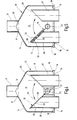
- Fig. 4 und 5
- jeweils einen schematischen Schnitt eines insbesondere als Abgasventil gestalteten Ventils gemäß einem zweiten bzw. dritten Ausführungsbeispiel.
- Fig. 1
- 2 is a schematic, perspective view of a valve designed in particular as an exhaust valve according to a first exemplary embodiment,
- Fig. 2
- 1 is a schematic side view of the valve in FIG. 1,
- Fig. 3
- a schematic section of the valve in Fig. 1,
- 4 and 5
- in each case a schematic section of a valve designed in particular as an exhaust valve according to a second or third embodiment.
In Fig. 1 bis 3 ist ein Ventil gemäß einem ersten Ausführungsbeispiel gezeigt, das
insbesondere als Abgasventil 10 ausgebildet ist und als solches zum Schalten
bzw. Umlenken des Abgasstromes im Abgassystem von Brennkraftmaschinen
dienen kann. Das Abgasventil 10 weist ein Ventilgehäuse 11 auf, dessen
Innenraum 12 mittels dreier Öffnungen 13, 14 und 15 nach außen hin geöffnet ist.
Das Abgasventil weist ferner einen Ventilkörper 16 auf, der der Steuerung des
Durchganges durch zumindest zwei dieser Öffnungen 13, 14, 15 dient, wobei
mittels des Ventilkörpers 16 entsprechend einer jeweiligen Ventilbetätigung, die
mittels eines schematisch angedeuteten Aktuators 40 erfolgt, der Durchgang
durch eine Öffnung jeweils sperrbar und von einer zweiten Öffnung zur dritten
Öffnung jeweils freigebbar ist. Der Aktuator 40 ist nur schematisch dargestellt. Die
Betätigung des Ventilkörpers 16 kann darüber z. B. pneumatisch oder auch
anderweitig geschehen.In Fig. 1 to 3, a valve according to a first embodiment is shown, the
is designed in particular as an
Das Ventilgehäuse 11 besteht aus Blech und ist als etwa trichterförmiges Blech-Tiefziehteil
mit einer Gehäuseöffnung 17 am engeren Ende und einer größeren
Gehäuseöffnung 18 am gegenüberliegenden, weiteren Ende ausgebildet.
Zumindest am weiteren Ende des Ventilgehäuses 11 ist eine separate
Flanschplatte 19 dicht befestigt, die die dortige Gehäuseöffnung 18 abdeckt. Diese
Flanschplatte 19 enthält in Anordnung nebeneinander zwei der insgesamt drei
Öffnungen, beim gezeigten Ausführungsbeispiel die Öffnungen 14 und 15.The
An der andere Gehäuseöffnung 17 am engeren Ende des Ventilgehäuses 11 ist
eine weitere Flanschplatte 20 dicht befestigt, die eine der Öffnungen enthält, beim
gezeigten Ausführungsbeispiel die Öffnung 13. At the other housing opening 17 at the narrower end of the
Der Durchlass durch die Öffnungen 13, 14 und 15 in den jeweiligen Flanschplatten
19 bzw. 20 ist dabei durch den Öffnungsquerschnitt der jeweiligen Öffnung in der
Flanschplatte vorgegeben. Die Öffnungen 13, 14 und 15 in der mindestens einen
Flanschplatte 19, 20 sind jeweils als Bohrungen in der Flanschplatte ausgebildet.
Zumindest eine der Flanschplatten, beim gezeigten Ausführungsbeispiel beide
Flanschplatten 19, 20, ist am Ventilgehäuse 11 durch Bördeln, Schweißen, Löten
od. dgl. befestigt.The passage through the
An derjenigen Flanschplatte 19, die an der Gehäuseöffnung 18 am weiteren Ende
des Ventilgehäuses 11 befestigt ist, ist eine schematisch angedeutete
Schwenkmechanik 21, zumindest eine Schwenklagerung 22, des Ventilkörpers 16
angebracht.At that
Die Flanschplatten 19, 20 weisen je Öffnung 13, 14, 15 einen die letztgenannte
Öffnung umgebenden Kragen 23, 24, 25 auf.The
Beim gezeigten Ausführungsbeispiel ist die eine Öffnung 13 am engeren Ende des
Ventilgehäuses 11 als Einlassöffnung ausgebildet und dient dort bei der
Ausbildung als Abgasventil 10 dem Abgaseintritt. Die beiden anderen Öffnungen
14, 15 am anderen, weiteren Gehäuseende des Ventilgehäuses 11 sind als
jeweilige Auslassöffnungen ausgebildet und dienen dort dem Austritt des
Abgases.In the embodiment shown, the one
Es versteht sich, dass die Verhältnisse auch vertauscht sein können, derart, dass
die beiden Öffnungen 14, 15 dem Abgaseintritt und die Öffnung 13 dem
Abgasaustritt dienen.It is understood that the relationships can also be reversed, such that
the two
Der Ventilkörper 16 ist als Klappe 26 ausgebildet, die im Innenraum 12 des
Ventilgehäuses 11 schwenkbar gelagert ist und in der jeweiligen Endstellung den
Durchgang von einer Öffnung 13 zur anderen Öffnung 14 bzw. zur Öffnung 15
sperrt. In dieser Endstellung bildet die Klappe 26 dabei eine innere Leitwand im
Gehäuseinnenraum 12 und gewährleistet gute Strömungsverhältnisse. Die Klappe
26 liegt in der jeweiligen Endstellung innen am Ventilgehäuse 11 dicht an. In der in
Fig. 3 gezeigten Endstellung der Klappe 26 ist der Durchgang durch die Öffnung
14 verschlossen, während die Öffnung 15 für den Auslass von bei der Öffnung 13
eingeleitetem Abgas geöffnet ist. In Fig. 3 ist gestrichelt angedeutet, dass die
Klappe 26 um einen Winkel von etwa 45° in die andere Endstellung schwenkbar
ist, in der der Durchgang durch die Öffnung 15 gesperrt und der Durchgang von
der Öffnung 13 zur Öffnung 14 freigegeben ist. Wenn gewünscht, sind auch
Zwischenstellungen der Klappe 26 mit Durchlass durch beide Öffnungen 14, 15
möglich.The
Wie insbesondere aus Fig. 3 ersichtlich ist, ist die Klappe 26 etwa mittig zwischen
beiden Öffnungen 14, 15 der am weiteren Ende des Ventilgehäuses 11
befestigten Flanschplatte 19 schwenkbar, vorzugsweise kardanisch, gelagert.As can be seen in particular from Fig. 3, the
Durch die Ausbildung des Ventilgehäuses 11 als etwa trichterförmiges Blech-Tiefziehteil
lässt sich das Ventilgehäuse 11 preiswert herstellen. Die einzelnen
Teile des Ventilgehäuses 11, nämlich letzteres sowie die Flanschplatten 19, 20,
lassen sich nach dem Baukastensystem modular aufbauen und können leicht an
andere Abmessungen angepasst werden. Die einzelnen Teile des Ventilgehäuses
11 lassen sich ferner jeweils gewichtsoptimiert herstellen, so dass das gesamte
Ventilgehäuse 11 ein möglichst geringes Gewicht hat. Auch ist die Herstellung der
einzelnen Teile des Ventilgehäuses 11 besonders einfach. Die technisch
komplexen Bearbeitungen bzw. Anformungen sind auf die Flanschplatten 19, 20
konzentriert. Da die Einzelteile erst am Schluss gefügt werden, ergibt sich eine
gute Zugänglichkeit für die Bearbeitung. Insgesamt ist das Ventil, insbesondere in
Gestalt als Abgasventil 10, leicht, kostengünstig und einfach im Aufbau und bei
allem in hohem Maße betriebssicher.Due to the design of the
Bei dem in Fig. 4 und Fig. 5 gezeigten zweiten bzw. dritten Ausführungsbeispiel sind für die Teile, die dem ersten Ausführungsbeispiel entsprechen, gleiche Bezugszeichen verwendet, so dass dadurch zur Vermeidung von Wiederholungen auf die Beschreibung des ersten Ausführungsbeispiels in Fig. 1 bis 3 verwiesen ist.In the second and third embodiments shown in FIGS. 4 and 5, respectively are the same for the parts that correspond to the first embodiment Reference numeral used, thereby thereby avoiding repetition refer to the description of the first embodiment in Fig. 1 to 3 is.
Beim zweiten Ausführungsbeispiel gemäß Fig. 4 ist das Ventilgehäuse 11
ebenfalls als Blech-Tiefziehteil ausgebildet und dabei etwa topfförmig oder
becherförmig. Am weiteren Ende des Ventilgehäuses 11 ist eine Flanschplatte 19
dicht befestigt, die in Anordnung nebeneinander zwei Öffnungen 14 und 15
enthält, wobei in diese Öffnungen 14 und 15 jeweils Rohrstücke 27, 28 eingesteckt
sind, die mit einem Ende in den Innenraum 12 des Ventilgehäuses 11 hineinragen
und am dortigen Ende jeweilige Anlageflächen 29 bzw. 30 für den Ventilkörper 16,
insbesondere die Klappe 26, in der jeweiligen Schließstellung bilden. An dem
einen, in das Ventilgehäuse 11 hineinragenden Ende sind die Rohrstücke 27, 28
abgeschrägt, z. B. unter einem Winkel von etwa 45°, derart, dass die
abgeschrägten Anlageflächen 29, 30 beider Rohrstücke 27, 28 etwa V-förmig
zueinander ausgerichtet sind. Die beiden eingesteckten Rohrstücke 27, 28 stehen
mit ihrem anderen Ende über die Flanschplatte 19 hinweg über. Sie sind in der
Flanschplatte 19, in die sie eingesteckt sind, durch Schweißen, Löten, Bördeln od.
dgl. befestigt.In the second embodiment according to FIG. 4, the
Bei der Gehäuseöffnung 17 am anderen, engeren Ende des Ventilgehäuses 11 ist
ein Rohrstück 31 vorgesehen, das mit dem Ventilgehäuse 11 entweder einstückig
ist oder damit dicht verbunden ist, z. B. durch Schweißen, Löten, Bördeln od. dgl..In the
Alle Rohrstücke 27, 28, 31 sind aus Blech-Stangenmaterial gebildet. Auf diese
Weise können das Ventilgehäuse 11 und die Rohrstücke 27, 28, 31 sehr einfach
ausgeführt werden. Insgesamt gelten auch für das zweite Ausführungsbeispiel die
gleichen Vorteile, die vorstehend zum ersten Ausführungsbeispiel dargelegt sind. All
Die Klappe 26 weist auf jeder Klappenseite eine mit der jeweiligen Anlagefläche
29, 30 zusammenwirkende Dichtfläche 32, 33 auf, die in Fig. 4 durch die Klappe
selbst gebildet ist.The
Beim dritten Ausführungsbeispiel in Fig. 5 ist statt dessen als Dichtfläche 32, 33 je
Klappenseite eine Platte 34, 35 vorgesehen, wobei die beiden Platten 34, 35
miteinander und/oder mit der Klappe 26 und/oder mit einem Halter od. dgl.
gelenkig, z. B. kardanisch, verbunden sind, wodurch Unebenheiten bzw.
Ungenauigkeiten bezüglich der Bearbeitung der Rohrstücke 27, 28 und bezüglich
der Positionierung dieser in einfacher Weise ausgeglichen werden.In the third embodiment in Fig. 5 is instead as a sealing
Claims (20)
dadurch gekennzeichnet, dass das Ventilgehäuse (11) als etwa trichterförmiges oder topfförmiges Blech-Tiefziehteil mit einer Gehäuseöffnung (17) am engeren Ende und einer größeren Gehäuseöffnung (18) am weiteren Ende ausgebildet ist, dass zumindest am weiteren Ende des Ventilgehäuses (11) eine die dortige Gehäuseöffnung (18) abdeckende separate Flanschplatte (19) dicht befestigt ist und dass die Flanschplatte (19) in Anordnung nebeneinander zwei der Öffnungen (13, 14, 15) enthält.Valve, in particular exhaust valve (10), with a valve housing (11) whose interior (12) is open towards the outside by means of three openings (13, 14, 15) and with a control of the passage through at least two of these openings (13 , 14, 15) serving valve body (16), by means of which according to a respective valve actuation of the passage through an opening in each case can be blocked and in each case from a second opening to the third opening,
characterized in that the valve housing (11) is formed as an approximately funnel-shaped or cup-shaped deep-drawn part with a housing opening (17) at the narrower end and a larger housing opening (18) at the other end, that at least at the other end of the valve housing (11) the local housing opening (18) covering the separate flange plate (19) is tightly fastened and that the flange plate (19) in arrangement next to each other two of the openings (13, 14, 15).
dadurch gekennzeichnet, dass an der Gehäuseöffnung (17) am engeren Ende eine weitere Flanschplatte (20) dicht befestigt ist, die eine der Öffnungen (13, 14, 15) enthält.Valve according to claim 1,
characterized in that at the housing opening (17) at the narrower end another flange plate (20) is tightly secured, which contains one of the openings (13, 14, 15).
dadurch gekennzeichnet, dass der Durchlass durch die Öffnungen (13, 14, 15) durch den Öffnungsquerschnitt der jeweiligen Öffnung in der mindestens einen Flanschplatte (19, 20) vorgegeben wird.Valve according to claim 1 or 2,
characterized in that the passage through the openings (13, 14, 15) is predetermined by the opening cross section of the respective opening in the at least one flange plate (19, 20).
dadurch gekennzeichnet, dass die Öffnungen (13, 14, 15) in der mindestens einen Flanschplatte (19, 20) als Bohrungen ausgebildet sind.Valve according to one of claims 1 to 3,
characterized in that the openings (13, 14, 15) in the at least one flange plate (19, 20) are formed as bores.
dadurch gekennzeichnet, dass an der Flanschplatte (19), die an der Gehäuseöffnung (18) am weiteren Ende des Ventilgehäuses (11) befestigt ist, eine Schwenkmechanik (21), zumindest eine Schwenklagerung (22), des Ventilkörpers (16) angebracht ist.Valve according to one of claims 1 to 4,
characterized in that on the flange plate (19) which is fixed to the housing opening (18) at the further end of the valve housing (11), a pivot mechanism (21), at least one pivot bearing (22) of the valve body (16) is mounted.
dadurch gekennzeichnet, dass zumindest eine der Flanschplatten (19, 20) am Ventilgehäuse (11) durch Bördeln, Schweißen, Löten od. dgl. befestigt ist.Valve according to one of claims 1 to 5,
characterized in that at least one of the flange plates (19, 20) is attached to the valve housing (11) by crimping, welding, soldering or the like.
dadurch gekennzeichnet, dass die Flanschplatten (19,20) je Öffnung (13, 14, 15) einen die Öffnung (13, 14, 15) umgebende Kragen (23, 24, 25) aufweisen.Valve according to one of claims 1 to 6,
characterized in that the flange plates (19,20) for each opening (13, 14, 15) has a the opening (13, 14, 15) surrounding the collar (23, 24, 25).
dadurch gekennzeichnet, dass die eine Öffnung (13) an einem Ende, insbesondere am engeren Ende, des Ventilgehäuses (11) als Einlassöffnung ausgebildet ist und dass die beiden anderen Öffnungen (14, 15) am anderen Ende, insbesondere am weiteren Gehäuseende, des Ventilgehäuses (11) als jeweilige Auslassöffnungen ausgebildet sind, oder dass die Einlass- und Auslassverhältnisse vertauscht sind.Valve according to one of claims 1 to 7,
characterized in that the one opening (13) at one end, in particular at the narrower end, of the valve housing (11) is designed as an inlet opening and in that the two other openings (14, 15) at the other end, in particular at the further housing end, of the valve housing (11) are formed as respective outlet openings, or that the inlet and outlet conditions are reversed.
dadurch gekennzeichnet, dass der Ventilkörper (16) als im Innenraum (12) des Ventilgehäuses (11) schwenkbar gelagerte Klappe (26) ausgebildet ist, die in der jeweiligen Endstellung den Durchgang von einer Öffnung (13) zur anderen Öffnung (14 bzw. 15) sperrt und dabei als innere Leitwand im Gehäuseinnenraum (12) ausgebildet ist.Valve according to one of claims 1 to 8,
characterized in that the valve body (16) as in the interior (12) of the valve housing (11) pivotally mounted flap (26) is formed in the respective end position, the passage from one opening (13) to the other opening (14 or 15 ) and thereby formed as an inner baffle in the housing interior (12).
dadurch gekennzeichnet, dass die Klappe (26) in der jeweiligen Endstellung innen am Ventilgehäuse (11) dicht anliegt.Valve according to claim 9,
characterized in that the flap (26) in the respective end position inside the valve housing (11) rests tightly.
dadurch gekennzeichnet, dass die Klappe (26) etwa mittig zwischen beiden Öffnungen (14, 15) der am weiteren Ende des Ventilgehäuses (11) befestigten Flanschplatte (19) schwenkbar, vorzugsweise kardanisch, gelagert ist.Valve according to claim 9 or 10,
characterized in that the flap (26) approximately centrally between two openings (14, 15) of the further end of the valve housing (11) fixed flange plate (19) pivotally, preferably gimbal-mounted.
dadurch gekennzeichnet, dass in die beiden Öffnungen (14, 15) der Flanschplatte (19) an der Gehäuseöffnung (18) am weiteren Ende des insbesondere etwa topfförmigen Ventilgehäuses (11) jeweils Rohrstücke (27, 28) eingesteckt sind, die mit einem Ende in den Innenraum (12) des Ventilgehäuses (11) hineinragen und am dortigen Ende jeweilige Anlageflächen (29, 30) für den Ventilkörper (16), insbesondere die Klappe (26), in der jeweiligen Schließstellung bilden.Valve according to one of claims 1 to 11,
characterized in that in the two openings (14, 15) of the flange plate (19) at the housing opening (18) at the other end of the particular cup-shaped valve housing (11) each pipe pieces (27, 28) are inserted, which with one end in protrude the interior (12) of the valve housing (11) and form at the local end respective contact surfaces (29, 30) for the valve body (16), in particular the flap (26), in the respective closed position.
dadurch gekennzeichnet, dass die Rohrstücke (27, 28) an dem einen Ende abgeschrägt sind, z. B. unter einem Winkel von etwa 45°, derart, dass die abgeschrägten Anlageflächen (29, 30) beider Rohrstücke (27, 28) etwa V-förmig zueinander ausgerichtet sind.Valve according to claim 12,
characterized in that the pipe pieces (27, 28) are chamfered at one end, z. B. at an angle of about 45 °, such that the tapered contact surfaces (29, 30) of the two pipe sections (27, 28) are aligned approximately V-shaped to each other.
dadurch gekennzeichnet, dass die beiden eingesteckten Rohrstücke (27, 28) mit ihrem anderen Ende über die Flanschplatte (19) hinweg überstehen.Valve according to claim 12 or 13,
characterized in that the two inserted pipe sections (27, 28) project beyond the flange plate (19) with its other end.
dadurch gekennzeichnet, dass die beiden eingesteckten Rohrstücke (27, 28) in der Flanschplatte (19), in die diese eingesteckt sind, durch Schweißen, Löten, Bördeln od. dgl. befestigt sind.Valve according to one of claims 12 to 14,
characterized in that the two inserted pipe sections (27, 28) od in the flange plate (19), in which they are inserted, by welding, soldering, flanging. The like. Are attached.
dadurch gekennzeichnet, dass bei der Gehäuseöffnung (17) am engeren Ende des Ventilgehäuses (11) ein Rohrstück (31) vorgesehen ist, das mit dem Ventilgehäuse (11) einstückig oder dicht verbunden ist, z. B. durch Schweißen, Löten, Bördeln od. dgl..Valve according to one of claims 12 to 15,
characterized in that at the housing opening (17) at the narrower end of the valve housing (11) has a piece of pipe (31) is provided which is integrally or tightly connected to the valve housing (11), for. B. by welding, soldering, flanging od. Like ..
dadurch gekennzeichnet, dass die Rohrstücke (27, 28, 31) aus Blech-Stangenmaterial gebildet sind. Valve according to one of claims 12 to 16,
characterized in that the pipe pieces (27, 28, 31) are formed of sheet metal bar stock.
dadurch gekennzeichnet, dass die Klappe (26) auf jeder Klappenseite eine mit einer Anlagenfläche (29, 30) zusammenwirkende Dichtfläche (32, 33) aufweist.Valve according to one of claims 12 to 17,
characterized in that the flap (26) on each flap side with a contact surface (29, 30) cooperating sealing surface (32, 33).
dadurch gekennzeichnet, dass als Dichtfläche (32, 33) je Klappenseite eine Platte (34, 35) vorgesehen ist.Valve according to claim 18,
characterized in that as a sealing surface (32, 33) per flap side, a plate (34, 35) is provided.
dadurch gekennzeichnet, dass die beiden Platten (34, 35) miteinander und/oder mit der Klappe (26) und/oder mit einem Halter gelenkig, z. B. kardanisch, verbunden sind.Valve according to claim 19,
characterized in that the two plates (34, 35) hinged together and / or with the flap (26) and / or with a holder, for. Gimbaled, are connected.
Applications Claiming Priority (2)
| Application Number | Priority Date | Filing Date | Title |
|---|---|---|---|
| DE10339623 | 2003-08-28 | ||
| DE10339623A DE10339623A1 (en) | 2003-08-28 | 2003-08-28 | Valve, in particular exhaust valve |
Publications (1)
| Publication Number | Publication Date |
|---|---|
| EP1510739A1 true EP1510739A1 (en) | 2005-03-02 |
Family
ID=34089231
Family Applications (1)
| Application Number | Title | Priority Date | Filing Date |
|---|---|---|---|
| EP04009636A Withdrawn EP1510739A1 (en) | 2003-08-28 | 2004-04-23 | Exhaust valve |
Country Status (2)
| Country | Link |
|---|---|
| EP (1) | EP1510739A1 (en) |
| DE (1) | DE10339623A1 (en) |
Cited By (9)
| Publication number | Priority date | Publication date | Assignee | Title |
|---|---|---|---|---|
| WO2006099965A1 (en) * | 2005-03-19 | 2006-09-28 | Daimlerchrysler Ag | Air-induction unit for an internal combustion engine, comprising a bypass flap assembly that can be inserted |
| EP1748179A1 (en) * | 2005-07-29 | 2007-01-31 | Valeo Termico S.A. | Control system for circulation of gas, in particular of exhaust gas of an engine |
| FR2908492A1 (en) * | 2006-11-13 | 2008-05-16 | Faurecia Sys Echappement | Three-way valve for motor vehicle's exhaust line, has large face including support surface with opposed portions near walls of inlet and outlet when flap is in one position, where face and body delimit passage from inlet to outlet |
| FR2916255A1 (en) * | 2007-05-18 | 2008-11-21 | Faurecia Sys Echappement | Three-way control valve for exhaust line of motor vehicle, has flap varying passage section of inlet openings, where section of one of inlet openings is larger than that of outlet opening of body in position of flap |
| FR2917801A1 (en) * | 2007-06-21 | 2008-12-26 | Faurecia Sys Echappement | Three-way control valve for exhaust line of motor vehicle, has closing unit with compressor valve coupled to jumper unit, where jumper unit is used for adopting closing position in which one of three openings is closed by compressor valve |
| EP2071171A1 (en) * | 2007-12-10 | 2009-06-17 | smk systeme metall kunststoff gmbh & co. | Flap device for exhaust recirculation system |
| CN103291433A (en) * | 2013-05-17 | 2013-09-11 | 上海交通大学 | Triaxial synchronous type variable exhaust branch reducing rate system |
| US20180058341A1 (en) * | 2016-08-24 | 2018-03-01 | Ford Global Technologies, Llc | Internal combustion engine with compressor, exhaust-gas recirculation arrangement and pivotable flap |
| US10281048B2 (en) | 2015-05-01 | 2019-05-07 | Eberspächer Exhaust Technology GmbH & Co. KG | Three-way flap valve with curved valve flap |
Families Citing this family (4)
| Publication number | Priority date | Publication date | Assignee | Title |
|---|---|---|---|---|
| DE102009015184B4 (en) * | 2009-03-31 | 2011-07-21 | Pierburg GmbH, 41460 | flap valve |
| DE102012111464B4 (en) | 2012-11-27 | 2018-05-09 | Hanon Systems | Bypass valve, as a two-way valve for exhaust gas flows of motor vehicles |
| DE102013107587A1 (en) * | 2013-07-17 | 2015-01-22 | BorgWarner Esslingen GmbH | Valve, in particular exhaust manifold for an internal combustion engine |
| DE102019103691A1 (en) * | 2019-02-14 | 2020-08-20 | Bayerische Motoren Werke Aktiengesellschaft | Exhaust gas recirculation cooler for an internal combustion engine |
Citations (6)
| Publication number | Priority date | Publication date | Assignee | Title |
|---|---|---|---|---|
| US325449A (en) * | 1885-09-01 | Cut-off | ||
| US2040930A (en) * | 1930-12-31 | 1936-05-19 | Foster Whecler Corp | Distributing mechanism |
| US2516510A (en) * | 1945-08-22 | 1950-07-25 | Pratt Co Henry | Swing valve |
| US2605076A (en) * | 1950-04-13 | 1952-07-29 | Allis Chalmers Mfg Co | Control valve for grain dividers |
| EP1447545A1 (en) * | 2003-02-17 | 2004-08-18 | Arvin Technologies, Inc. | Valve for an exhaust pipe |
| FR2854200A1 (en) * | 2003-04-25 | 2004-10-29 | Faurecia Sys Echappement | Exhaust line for vehicle internal combustion engine, has three-way valve placed downstream of upstream pipe and including check valve to direct gas through heat exchanger in one position and by-pass pipe in another position |
-
2003
- 2003-08-28 DE DE10339623A patent/DE10339623A1/en not_active Withdrawn
-
2004
- 2004-04-23 EP EP04009636A patent/EP1510739A1/en not_active Withdrawn
Patent Citations (6)
| Publication number | Priority date | Publication date | Assignee | Title |
|---|---|---|---|---|
| US325449A (en) * | 1885-09-01 | Cut-off | ||
| US2040930A (en) * | 1930-12-31 | 1936-05-19 | Foster Whecler Corp | Distributing mechanism |
| US2516510A (en) * | 1945-08-22 | 1950-07-25 | Pratt Co Henry | Swing valve |
| US2605076A (en) * | 1950-04-13 | 1952-07-29 | Allis Chalmers Mfg Co | Control valve for grain dividers |
| EP1447545A1 (en) * | 2003-02-17 | 2004-08-18 | Arvin Technologies, Inc. | Valve for an exhaust pipe |
| FR2854200A1 (en) * | 2003-04-25 | 2004-10-29 | Faurecia Sys Echappement | Exhaust line for vehicle internal combustion engine, has three-way valve placed downstream of upstream pipe and including check valve to direct gas through heat exchanger in one position and by-pass pipe in another position |
Cited By (11)
| Publication number | Priority date | Publication date | Assignee | Title |
|---|---|---|---|---|
| WO2006099965A1 (en) * | 2005-03-19 | 2006-09-28 | Daimlerchrysler Ag | Air-induction unit for an internal combustion engine, comprising a bypass flap assembly that can be inserted |
| EP1748179A1 (en) * | 2005-07-29 | 2007-01-31 | Valeo Termico S.A. | Control system for circulation of gas, in particular of exhaust gas of an engine |
| ES2300163A1 (en) * | 2005-07-29 | 2008-06-01 | Valeo Termico, S.A. | Control system for circulation of gas, in particular of exhaust gas of an engine |
| FR2908492A1 (en) * | 2006-11-13 | 2008-05-16 | Faurecia Sys Echappement | Three-way valve for motor vehicle's exhaust line, has large face including support surface with opposed portions near walls of inlet and outlet when flap is in one position, where face and body delimit passage from inlet to outlet |
| FR2916255A1 (en) * | 2007-05-18 | 2008-11-21 | Faurecia Sys Echappement | Three-way control valve for exhaust line of motor vehicle, has flap varying passage section of inlet openings, where section of one of inlet openings is larger than that of outlet opening of body in position of flap |
| FR2917801A1 (en) * | 2007-06-21 | 2008-12-26 | Faurecia Sys Echappement | Three-way control valve for exhaust line of motor vehicle, has closing unit with compressor valve coupled to jumper unit, where jumper unit is used for adopting closing position in which one of three openings is closed by compressor valve |
| EP2071171A1 (en) * | 2007-12-10 | 2009-06-17 | smk systeme metall kunststoff gmbh & co. | Flap device for exhaust recirculation system |
| CN103291433A (en) * | 2013-05-17 | 2013-09-11 | 上海交通大学 | Triaxial synchronous type variable exhaust branch reducing rate system |
| US10281048B2 (en) | 2015-05-01 | 2019-05-07 | Eberspächer Exhaust Technology GmbH & Co. KG | Three-way flap valve with curved valve flap |
| US20180058341A1 (en) * | 2016-08-24 | 2018-03-01 | Ford Global Technologies, Llc | Internal combustion engine with compressor, exhaust-gas recirculation arrangement and pivotable flap |
| US10934945B2 (en) * | 2016-08-24 | 2021-03-02 | Ford Global Technologies, Llc | Internal combustion engine with compressor, exhaust-gas recirculation arrangement and pivotable flap |
Also Published As
| Publication number | Publication date |
|---|---|
| DE10339623A1 (en) | 2005-03-24 |
Similar Documents
| Publication | Publication Date | Title |
|---|---|---|
| EP2229550B1 (en) | Exhaust gas recirculation valve for a motor vehicle | |
| EP1510739A1 (en) | Exhaust valve | |
| DE3503434C2 (en) | ||
| DE4339393A1 (en) | Flat rotary valve | |
| EP1331116B1 (en) | Air nozzle | |
| DE1285820B (en) | Control valve that can be switched to different operating modes | |
| DE102005043008A1 (en) | Valve housing body | |
| EP0305821A1 (en) | Device for sealing off a tube branch | |
| EP3021023A1 (en) | Sanitary fitting with offset operating element tilt axis | |
| EP0638154A1 (en) | Control valve for a fluid medium flowing under pressure. | |
| DE202006020515U1 (en) | Device for controlling the flow of a gaseous or liquid medium | |
| DE8225789U1 (en) | Device for controlling a pneumatic device | |
| DE102023120030A1 (en) | Ball valve | |
| DE102013109891A1 (en) | valve assembly | |
| DE1915267B2 (en) | INPUT BOX FOR NOZZLE GROUP CONTROL OF STEAM TURBINES | |
| EP0180146A2 (en) | Punching machine | |
| DE4446946C1 (en) | Sliding valve with large nominal width | |
| EP0436883A1 (en) | Clamping device | |
| DE102013107587A1 (en) | Valve, in particular exhaust manifold for an internal combustion engine | |
| DE102015111252B4 (en) | Valve for an exhaust system of an internal combustion engine | |
| DE602004011602T2 (en) | Pressure reducing device for gas cylinder | |
| DE60126778T2 (en) | FLAP VALVE FOR AN AIR CONDITIONING CONTAINING A HOUSING WITH A ROTATABLE FLAP | |
| EP0911494A2 (en) | Variable valve operating device for internal combustion engines | |
| DE1228478B (en) | Slide valve | |
| DE19944841A1 (en) | Shaping contour part for use in die casting tools |
Legal Events
| Date | Code | Title | Description |
|---|---|---|---|
| PUAI | Public reference made under article 153(3) epc to a published international application that has entered the european phase |
Free format text: ORIGINAL CODE: 0009012 |
|
| AK | Designated contracting states |
Kind code of ref document: A1 Designated state(s): AT BE BG CH CY CZ DE DK EE ES FI FR GB GR HU IE IT LI LU MC NL PL PT RO SE SI SK TR |
|
| AX | Request for extension of the european patent |
Extension state: AL HR LT LV MK |
|
| 17P | Request for examination filed |
Effective date: 20050706 |
|
| AKX | Designation fees paid |
Designated state(s): DE ES FR GB IT SE |
|
| STAA | Information on the status of an ep patent application or granted ep patent |
Free format text: STATUS: THE APPLICATION IS DEEMED TO BE WITHDRAWN |
|
| 18D | Application deemed to be withdrawn |
Effective date: 20060222 |