EP1510676A1 - Gasturbinenanlage - Google Patents
Gasturbinenanlage Download PDFInfo
- Publication number
- EP1510676A1 EP1510676A1 EP03018413A EP03018413A EP1510676A1 EP 1510676 A1 EP1510676 A1 EP 1510676A1 EP 03018413 A EP03018413 A EP 03018413A EP 03018413 A EP03018413 A EP 03018413A EP 1510676 A1 EP1510676 A1 EP 1510676A1
- Authority
- EP
- European Patent Office
- Prior art keywords
- gas turbine
- compressor
- turbine plant
- turbocompressor
- plant
- Prior art date
- Legal status (The legal status is an assumption and is not a legal conclusion. Google has not performed a legal analysis and makes no representation as to the accuracy of the status listed.)
- Granted
Links
- 239000000446 fuel Substances 0.000 claims abstract description 15
- 239000002826 coolant Substances 0.000 claims description 8
- 238000001816 cooling Methods 0.000 claims description 6
- 239000010687 lubricating oil Substances 0.000 claims description 6
- 238000000605 extraction Methods 0.000 claims description 5
- 238000010438 heat treatment Methods 0.000 abstract 1
- 239000003570 air Substances 0.000 description 34
- 238000002485 combustion reaction Methods 0.000 description 8
- 239000000203 mixture Substances 0.000 description 7
- XLYOFNOQVPJJNP-UHFFFAOYSA-N water Substances O XLYOFNOQVPJJNP-UHFFFAOYSA-N 0.000 description 5
- 230000006835 compression Effects 0.000 description 4
- 238000007906 compression Methods 0.000 description 4
- 238000000034 method Methods 0.000 description 3
- 239000012080 ambient air Substances 0.000 description 1
- 230000033228 biological regulation Effects 0.000 description 1
- 230000015572 biosynthetic process Effects 0.000 description 1
- 238000010276 construction Methods 0.000 description 1
- 239000000498 cooling water Substances 0.000 description 1
- 230000007423 decrease Effects 0.000 description 1
- 230000003247 decreasing effect Effects 0.000 description 1
- 238000002347 injection Methods 0.000 description 1
- 239000007924 injection Substances 0.000 description 1
- 230000008092 positive effect Effects 0.000 description 1
- 230000001105 regulatory effect Effects 0.000 description 1
- 230000000630 rising effect Effects 0.000 description 1
- 238000010792 warming Methods 0.000 description 1
Images

Classifications
-
- F—MECHANICAL ENGINEERING; LIGHTING; HEATING; WEAPONS; BLASTING
- F01—MACHINES OR ENGINES IN GENERAL; ENGINE PLANTS IN GENERAL; STEAM ENGINES
- F01D—NON-POSITIVE DISPLACEMENT MACHINES OR ENGINES, e.g. STEAM TURBINES
- F01D13/00—Combinations of two or more machines or engines
- F01D13/003—Combinations of two or more machines or engines with at least two independent shafts, i.e. cross-compound
-
- F—MECHANICAL ENGINEERING; LIGHTING; HEATING; WEAPONS; BLASTING
- F02—COMBUSTION ENGINES; HOT-GAS OR COMBUSTION-PRODUCT ENGINE PLANTS
- F02C—GAS-TURBINE PLANTS; AIR INTAKES FOR JET-PROPULSION PLANTS; CONTROLLING FUEL SUPPLY IN AIR-BREATHING JET-PROPULSION PLANTS
- F02C3/00—Gas-turbine plants characterised by the use of combustion products as the working fluid
- F02C3/04—Gas-turbine plants characterised by the use of combustion products as the working fluid having a turbine driving a compressor
- F02C3/13—Gas-turbine plants characterised by the use of combustion products as the working fluid having a turbine driving a compressor having variable working fluid interconnections between turbines or compressors or stages of different rotors
-
- F—MECHANICAL ENGINEERING; LIGHTING; HEATING; WEAPONS; BLASTING
- F02—COMBUSTION ENGINES; HOT-GAS OR COMBUSTION-PRODUCT ENGINE PLANTS
- F02C—GAS-TURBINE PLANTS; AIR INTAKES FOR JET-PROPULSION PLANTS; CONTROLLING FUEL SUPPLY IN AIR-BREATHING JET-PROPULSION PLANTS
- F02C7/00—Features, components parts, details or accessories, not provided for in, or of interest apart form groups F02C1/00 - F02C6/00; Air intakes for jet-propulsion plants
- F02C7/12—Cooling of plants
- F02C7/16—Cooling of plants characterised by cooling medium
- F02C7/18—Cooling of plants characterised by cooling medium the medium being gaseous, e.g. air
- F02C7/185—Cooling means for reducing the temperature of the cooling air or gas
-
- F—MECHANICAL ENGINEERING; LIGHTING; HEATING; WEAPONS; BLASTING
- F02—COMBUSTION ENGINES; HOT-GAS OR COMBUSTION-PRODUCT ENGINE PLANTS
- F02C—GAS-TURBINE PLANTS; AIR INTAKES FOR JET-PROPULSION PLANTS; CONTROLLING FUEL SUPPLY IN AIR-BREATHING JET-PROPULSION PLANTS
- F02C9/00—Controlling gas-turbine plants; Controlling fuel supply in air- breathing jet-propulsion plants
- F02C9/16—Control of working fluid flow
Definitions
- the invention relates to a gas turbine plant with a one Gas turbine associated compressor.
- the power delivered by a gas turbine plant depends strongly from the current ambient temperature. It sinks the output power with increasing ambient temperature, because this is the compressor mass flow through the gas turbine decreased.
- Intake air of the gas turbine for example, by evaporative cooling cool.
- This measure only shows dry ambient air and preferably high ambient temperatures good results. Furthermore, this measure requires a high water consumption.
- a further known method involves the injection of water in the compressor of the gas turbine (wet compression).
- wet compression a large amount of completely desalinated water needed.
- the lifetime is reduced at least some components of the gas turbine.
- the invention is therefore based on the object, a gas turbine plant specify the type mentioned, in which an increase in performance in a simple way and without serious Disadvantages for a continuous operation of the system possible is.
- the object is achieved by a gas turbine plant with a compressor associated with a gas turbine (Gas turbine compressor), wherein the compressor is a separate Turbo compressor fluidly at least partially parallel is switched.
- Gas turbine compressor gas turbine compressor
- the separate turbo-compressor increases the mass flow compressed air which is supplied to the gas turbine. Thereby Compared to a gas turbine without separate turbocompressors an increased output of the Gas turbine plant, the efficiency of the gas turbine plant and their life are not affected.
- the compressor of the gas turbine must be that of the turbo compressor Provided additional air not from the ambient pressure compress the desired final pressure, since this task at least partly the turbo compressor takes over. This increases the power delivered by the gas turbine is stronger than proportional to the increase in the mass flow of the compressed Air flowing to the turbine.
- the turbocompressor driven by an electric motor.
- compressed air of the turbo compressor is the Compressor supplied via means for compressor air extraction, which are covered by the gas turbine plant.
- compressor air extraction In many gas turbine plants means for compressor air extraction operationally necessary and therefore already available, For example, blow-off pipes, cooling air ducts or Overflow lines.
- This means for compressor air extraction serve in known gas turbine plants essentially either for pressure reduction of the compressor air or for discharge at least a portion of the compressor air to this example to supply a cooling device.
- the gas turbine plant designed as a gas and steam power plant.
- the Turbo compressor at least two compressor stages.
- an intercooler is switched, which preferably as a fuel preheater is trained.
- the pre-compressed one increases Air the compressor mass flow on and on the other is the preheating of the gas turbine fuel mixture accomplished so that so far used, known Heat exchangers can be omitted. If the preheating of the Fuel mixture behind the control valves for the fuel mixture takes place, then a feeder for designed the fuel mixture for cold gas and thus cost will be realized.
- the intercooler by means of a generator or another component of the gas turbine plant assigned Coolant supply supplied with coolant.
- This embodiment can be realized with particularly little effort, if for intermediate cooling of the compressed air of the turbocompressor a coolant, such as cooling water needed becomes.
- This coolant can then be of a mostly anyway existing coolant supply, for example, for the generator often only a few Meters away.
- turbocompressor by means of a gas turbine associated lubricating oil supply supplied with lubricating oil.
- the turbocompressor during operation of the Gas turbine plant operated at its rated power.
- the turbo compressor runs with the maximum continuous power, for which it is designed.
- a power control for the turbocompressor can be omitted since the benefit scheme is regulated by means of a change in the Air quantity to be taken over exclusively by the gas turbine can.
- the additional, compacted, provided by the turbo-compressor Combustion air for the gas turbine is the gas turbine by means of the control flap according to a desired control characteristic supplied, which, for example, a slow and even feeding or removing the additional Combustion air when starting and stopping the turbocompressor allowed.
- the control characteristic may be, for example to act a control program for a motor, which the control flap is actuated.
- the turbo compressor is, for example, with the control flap closed started. Once the pressure in front of the control flap is greater than the pressure downstream of the gas turbine associated Compressor, the control flap will be continuous from its closed position to its fully opened Position brought. This opening process, for example 60 sec. Since this is the compressor mass flow increased slowly enough, the power control of the gas turbine alone be adopted.
- turbo-compressor may further be omitted, for example Operate by moving the control flap continuously from its open position to its closed position is brought, e.g. within 60 sec. Also here is the Change in the compressor mass flow sufficiently slow, so that the power control of the gas turbine alone easily accomplished via an adjustment of their vanes can be.
- the check valve is preferably hydraulic or pneumatically actuated.
- Such actuation of the non-return valve supports the closing of this flap in case of failure of the turbocompressor, so that the turbo compressor as soon as possible from the Gas turbine can be decoupled.
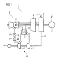
- It comprises a compressor 9, which together with a Gas turbine 5 and a generator 11 on a common Wave is arranged.
- the combustion of the gaseous fuel in a combustion chamber 25 requires the addition of air 31, which increases the efficiency of combustion by means of the compressor 9 compressed and then introduced into the combustion chamber 25.
- the air 31 is sucked by means of an aspirator 7 (intake) and fed to the compressor 9.
- Turbo compressor 13 Parallel to the compressor 9 is in the gas turbine plant 1 a Turbo compressor 13 is arranged, which also with air 31st is charged.
- the turbocompressor 13 comprises a first compressor stage 15 and a second compressor stage 17.
- the drive of the turbocompressor 13 takes place by means of an electric motor 19th
- the control flap 27 is a motor 33 according to a Control characteristic actuated.
- control flap 27 is opened continuously or closed.
- control flap 27 is usually in one constant opening position.
- a check valve 29 is provided in case of failure of the turbocompressor 13, the air backflow of the gas turbine 5 interrupt as quickly as possible to be able to.
- This check valve 29 is abruptly in this case brought a closed position.
- FIG 2 shows a further embodiment of the invention.
- the turbo compressor 13 the Compressor 9 fluidly connected only partially in parallel.
- compressed air is doing the compressor 9 at a certain pressure level 35th supplied to the compressor 9.
- the further compression to one desired final pressure then takes over the compressor.
- a gas turbine plant according to the invention can be describe as follows:
Landscapes
- Engineering & Computer Science (AREA)
- Chemical & Material Sciences (AREA)
- Combustion & Propulsion (AREA)
- Mechanical Engineering (AREA)
- General Engineering & Computer Science (AREA)
- Physics & Mathematics (AREA)
- Fluid Mechanics (AREA)
- Structures Of Non-Positive Displacement Pumps (AREA)
- Separation By Low-Temperature Treatments (AREA)
- Fuel Cell (AREA)
- Engine Equipment That Uses Special Cycles (AREA)
- Supercharger (AREA)
Abstract
Description
- FIG 1
- eine erfindungsgemäße Gasturbinenanlage mit einem einer Gasturbine zugeordneten Verdichter sowie einen zweistufigen Turboverdichter, der mit dem Verdichter vollständig parallel geschaltet ist, und
- FIG 2
- eine weitere erfindungsgemäße Gasturbinenanlage, wobei der Turboverdichter dem Verdichter strömungstechnisch teilweise parallel geschaltet ist.
Claims (14)
- Gasturbinenanlage (1) mit einem einer Gasturbine (5) zugeordneten Verdichter (9),
gekennzeichnet durch
einen dem Verdichter (9) strömungstechnisch zumindest teilweise parallel geschalteten separaten Turboverdichter (13) . - Gasturbinenanlage (1) nach Anspruch 1,
dadurch gekennzeichnet, dass
der Turboverdichter (9) von einem Elektromotor (19) antreibbar ist. - Gasturbinenanlage (1) nach einem der Ansprüche 1 oder 2,
dadurch gekennzeichnet, dass
mittels des Turboverdichters (13) verdichtete Luft (31) dem Verdichter (9) über von der Gasturbinenanlage (1) umfasste Mittel zur Verdichterluftentnahme zuführbar sind. - Gasturbinenanlage (1) nach Anspruch 3,
dadurch gekennzeichnet, dass
die Mittel zur Verdichterluftentnahme mindestens eine Komponente aus der Gruppe (Abblaseleitung, Kühlluftleitung, Überströmleitung} umfassen. - Gasturbinenanlage (1) nach einem der Ansprüche 1 bis 4,
wobei die Gasturbinenanlage (1) als eine Gas- und Dampfkraftanlage ausgebildet ist. - Gasturbinenanlage (1) nach einem der Ansprüche 1 bis 5,
dadurch gekennzeichnet, dass
der Turboverdichter (13) mindestens zwei Verdichterstufen (15,17) umfasst. - Gasturbinenanlage (1) nach Anspruch 6,
gekennzeichnet durch
einen zwischen zwei der Verdichterstufen (15,17) geschalteten Zwischenkühler. - Gasturbinenanlage nach Anspruch 7,
dadurch gekennzeichnet, dass
der Zwischenkühler als Brennstoffvorwärmer (21) ausgebildet ist. - Gasturbinenanlage nach Anspruch 7 oder 8,
dadurch gekennzeichnet, dass
der Zwischenkühler mittels einer einem Generator (11) oder einer anderen Komponente der Gasturbinenanlage (1) zugeordneten Kühlmittelversorgung mit Kühlmittel versorgbar ist. - Gasturbinenanlage (1) nach einem der Ansprüche 1 bis 9,
dadurch gekennzeichnet, dass
der Turboverdichter (13) mittels einer der Gasturbine zugeordneten Schmierölversorgung mit Schmieröl versorgbar ist. - Gasturbinenanlage (1) nach einem der Ansprüche 1 bis 10,
dadurch gekennzeichnet, dass
der Turboverdichter (13) während des Betriebs der Gasturbinenanlage (1) mit seiner Nennleistung betrieben ist. - Gasturbinenanlage (1) nach einem der Ansprüche 1 bis 11,
dadurch gekennzeichnet, dass
die mittels des Turboverdichters (13) verdichtete Luft (31) mittels einer Regelklappe (27) der Gasturbine (5) zuführbar ist, wobei die Regelklappe (27) gemäß einer Regelcharakteristik geöffnet und geschlossen werden kann. - Gasturbinenanlage (1) nach einem der Ansprüche 1 bis 12,
dadurch gekennzeichnet, dass eine Rückströmung der mittels des Verdichters (9) verdichteten Luft (31) zum Turboverdichter (13) mittels einer Rückschlagklappe (29) schlagartig unterbrechbar ist. - Gasturbinenanlage (1) nach Anspruch 13,
dadurch gekennzeichnet, dass
die Rückschlagklappe (29) hydraulisch oder pneumatisch betätigbar ist.
Priority Applications (5)
| Application Number | Priority Date | Filing Date | Title |
|---|---|---|---|
| EP03018413A EP1510676B1 (de) | 2003-08-13 | 2003-08-13 | Gasturbinenanlage |
| DE50308545T DE50308545D1 (de) | 2003-08-13 | 2003-08-13 | Gasturbinenanlage |
| ES03018413T ES2292886T3 (es) | 2003-08-13 | 2003-08-13 | Planta de turbina a gas. |
| AT03018413T ATE377701T1 (de) | 2003-08-13 | 2003-08-13 | Gasturbinenanlage |
| US10/909,805 US7024860B2 (en) | 2003-08-13 | 2004-07-31 | Gas-turbine installation |
Applications Claiming Priority (1)
| Application Number | Priority Date | Filing Date | Title |
|---|---|---|---|
| EP03018413A EP1510676B1 (de) | 2003-08-13 | 2003-08-13 | Gasturbinenanlage |
Publications (2)
| Publication Number | Publication Date |
|---|---|
| EP1510676A1 true EP1510676A1 (de) | 2005-03-02 |
| EP1510676B1 EP1510676B1 (de) | 2007-11-07 |
Family
ID=34089587
Family Applications (1)
| Application Number | Title | Priority Date | Filing Date |
|---|---|---|---|
| EP03018413A Expired - Lifetime EP1510676B1 (de) | 2003-08-13 | 2003-08-13 | Gasturbinenanlage |
Country Status (5)
| Country | Link |
|---|---|
| US (1) | US7024860B2 (de) |
| EP (1) | EP1510676B1 (de) |
| AT (1) | ATE377701T1 (de) |
| DE (1) | DE50308545D1 (de) |
| ES (1) | ES2292886T3 (de) |
Cited By (1)
| Publication number | Priority date | Publication date | Assignee | Title |
|---|---|---|---|---|
| EP1712761A3 (de) * | 2005-04-08 | 2009-08-26 | United Technologies Corporation | Elektrisch gekoppeltes Zweiwellen-Gasturbinentriebwerk |
Families Citing this family (9)
| Publication number | Priority date | Publication date | Assignee | Title |
|---|---|---|---|---|
| US20050135934A1 (en) * | 2003-12-22 | 2005-06-23 | Mechanology, Llc | Use of intersecting vane machines in combination with wind turbines |
| US8172886B2 (en) | 2004-12-14 | 2012-05-08 | Depuy Products, Inc. | Bone plate with pre-assembled drill guide tips |
| US7935126B2 (en) | 2006-03-20 | 2011-05-03 | Depuy Products, Inc. | Bone plate shaping system |
| EP2397083B1 (de) * | 2007-11-02 | 2014-05-07 | Biomet C.V. | Fixiersystem für Ellbogenbruch |
| US8191410B2 (en) * | 2009-08-28 | 2012-06-05 | General Electric Company | Mechanical drive train for testing full scale compressor rigs and gas turbines |
| ITFI20120292A1 (it) * | 2012-12-24 | 2014-06-25 | Nuovo Pignone Srl | "gas turbines in mechanical drive applications and operating methods" |
| US20160237904A1 (en) * | 2015-02-13 | 2016-08-18 | General Electric Company | Systems and methods for controlling an inlet air temperature of an intercooled gas turbine engine |
| US11112118B2 (en) * | 2016-06-27 | 2021-09-07 | General Electric Company | Gas turbine lower heating value methods and systems |
| US10731568B2 (en) * | 2016-11-23 | 2020-08-04 | General Electric Company | Systems and methods for reducing airflow imbalances in turbines |
Citations (4)
| Publication number | Priority date | Publication date | Assignee | Title |
|---|---|---|---|---|
| DE2541715A1 (de) * | 1974-09-20 | 1976-04-01 | Hitachi Ltd | Turbo-aggregat |
| US4949544A (en) * | 1988-12-06 | 1990-08-21 | General Electric Company | Series intercooler |
| US5680752A (en) * | 1992-08-28 | 1997-10-28 | Abb Carbon Ab | Gas turbine plant with additional compressor |
| EP1128039A2 (de) * | 2000-02-25 | 2001-08-29 | Hitachi, Ltd. | Gasturbine |
Family Cites Families (1)
| Publication number | Priority date | Publication date | Assignee | Title |
|---|---|---|---|---|
| DE2450710A1 (de) * | 1974-10-25 | 1976-05-13 | Bbc Brown Boveri & Cie | Verfahren zum betrieb einer turbomaschinenanlage und anlage zur durchfuehrung des verfahrens |
-
2003
- 2003-08-13 DE DE50308545T patent/DE50308545D1/de not_active Expired - Lifetime
- 2003-08-13 ES ES03018413T patent/ES2292886T3/es not_active Expired - Lifetime
- 2003-08-13 AT AT03018413T patent/ATE377701T1/de active
- 2003-08-13 EP EP03018413A patent/EP1510676B1/de not_active Expired - Lifetime
-
2004
- 2004-07-31 US US10/909,805 patent/US7024860B2/en not_active Expired - Fee Related
Patent Citations (4)
| Publication number | Priority date | Publication date | Assignee | Title |
|---|---|---|---|---|
| DE2541715A1 (de) * | 1974-09-20 | 1976-04-01 | Hitachi Ltd | Turbo-aggregat |
| US4949544A (en) * | 1988-12-06 | 1990-08-21 | General Electric Company | Series intercooler |
| US5680752A (en) * | 1992-08-28 | 1997-10-28 | Abb Carbon Ab | Gas turbine plant with additional compressor |
| EP1128039A2 (de) * | 2000-02-25 | 2001-08-29 | Hitachi, Ltd. | Gasturbine |
Cited By (2)
| Publication number | Priority date | Publication date | Assignee | Title |
|---|---|---|---|---|
| EP1712761A3 (de) * | 2005-04-08 | 2009-08-26 | United Technologies Corporation | Elektrisch gekoppeltes Zweiwellen-Gasturbinentriebwerk |
| EP2466094A1 (de) * | 2005-04-08 | 2012-06-20 | United Technologies Corporation | Elektrisch gekoppelter Vorverdichter für ein Turbinentriebwerk |
Also Published As
| Publication number | Publication date |
|---|---|
| DE50308545D1 (de) | 2007-12-20 |
| ATE377701T1 (de) | 2007-11-15 |
| EP1510676B1 (de) | 2007-11-07 |
| US20050086939A1 (en) | 2005-04-28 |
| US7024860B2 (en) | 2006-04-11 |
| ES2292886T3 (es) | 2008-03-16 |
Similar Documents
| Publication | Publication Date | Title |
|---|---|---|
| EP1591644B1 (de) | Vorrichtung zur Ausnutzung der Abwärme von Verdichtern | |
| EP0566868B1 (de) | Verfahren zum Betrieb einer Gasturbogruppe | |
| DE2657733C2 (de) | Verfahren zum Teillastbetrieb einer Gasturbinenanlage | |
| DE112007002957B4 (de) | Anordnung für einen aufgeladenen Verbrennungsmotor | |
| DD157571A5 (de) | Verfahren und vorrichtung zur leistungserzeugung mittels aufgeladener brennkraftmaschine | |
| DE2441873A1 (de) | Verfahren und vorrichtung zur aufbereitung der ansaugluft eines aufgeladenen dieselmotors mit schwachem kompressionsgrad | |
| DE10321572A1 (de) | Ladeluftverdichter für eine Brennkraftmaschine, Brennkraftmaschine und Verfahren hierzu | |
| DE10331187B4 (de) | Hubkolbenbrennkraftmaschine | |
| EP2067940A2 (de) | Verfahren zum Betrieb eines Kombikraftwerks sowie Kombikfartwerk zur Durchführung des Verfahrens | |
| EP1510676B1 (de) | Gasturbinenanlage | |
| DE102009044913A1 (de) | Brennkraftmaschine | |
| EP0592059B1 (de) | Verfahren und Vorrichtung zum Verdichten von Luft | |
| AT510317A1 (de) | Elektrisches kraftwerk | |
| DE102014206474A1 (de) | Anlage zum Bereitstellen von Wärmeenergie für Wärmeverbraucher | |
| DE10001063B4 (de) | Mechanisch angetriebener Kompressor für eine Brennkraftmaschine | |
| DE4123208C2 (de) | Verdichteranlage | |
| EP1167721A2 (de) | Verfahren zum Kühlen einer Gasturbinenanlage sowie Gasturbinenanlage zur Durchführung des Verfahrens | |
| DE102017120369A1 (de) | Mikrogasturbinenanordnung und Verfahren zum Betreiben einer Mikrogasturbinenanordnung | |
| EP3179067B1 (de) | Abgasturbolader für ein kraftfahrzeug | |
| DE870616C (de) | Mit fluessigen oder gasfoermigen Brennstoffen betriebene, mit einer Abgasturbine undeinem Aufladegeblaese verbundene Zweitakt-brennkraftmaschine | |
| DE102004001371A1 (de) | Brennkraftmaschine mit Abgasrückführung | |
| DE102012108576A1 (de) | Mehrstufiger Kolbenverdichter mit Leerlaufventilen zur Erzeugung einer Leerlauffunktion | |
| DE102022118387A1 (de) | Brayton-Kreisprozess-Maschine und Verfahren zum Betreiben einer Brayton-Kreisprozess-Maschine | |
| DE603845C (de) | Gasturbinenanlage | |
| DE102012009726A1 (de) | Effizienssteigerungsvorrichtung einesAntriebs |
Legal Events
| Date | Code | Title | Description |
|---|---|---|---|
| PUAI | Public reference made under article 153(3) epc to a published international application that has entered the european phase |
Free format text: ORIGINAL CODE: 0009012 |
|
| AK | Designated contracting states |
Kind code of ref document: A1 Designated state(s): AT BE BG CH CY CZ DE DK EE ES FI FR GB GR HU IE IT LI LU MC NL PT RO SE SI SK TR |
|
| AX | Request for extension of the european patent |
Extension state: AL LT LV MK |
|
| 17P | Request for examination filed |
Effective date: 20050321 |
|
| 17Q | First examination report despatched |
Effective date: 20050429 |
|
| AKX | Designation fees paid |
Designated state(s): AT BE BG CH CY CZ DE DK EE ES FI FR GB GR HU IE IT LI LU MC NL PT RO SE SI SK TR |
|
| 17Q | First examination report despatched |
Effective date: 20050429 |
|
| GRAP | Despatch of communication of intention to grant a patent |
Free format text: ORIGINAL CODE: EPIDOSNIGR1 |
|
| GRAS | Grant fee paid |
Free format text: ORIGINAL CODE: EPIDOSNIGR3 |
|
| GRAA | (expected) grant |
Free format text: ORIGINAL CODE: 0009210 |
|
| AK | Designated contracting states |
Kind code of ref document: B1 Designated state(s): AT BE BG CH CY CZ DE DK EE ES FI FR GB GR HU IE IT LI LU MC NL PT RO SE SI SK TR |
|
| REG | Reference to a national code |
Ref country code: GB Ref legal event code: FG4D Free format text: NOT ENGLISH |
|
| GBT | Gb: translation of ep patent filed (gb section 77(6)(a)/1977) |
Effective date: 20071107 |
|
| REG | Reference to a national code |
Ref country code: IE Ref legal event code: FG4D Free format text: LANGUAGE OF EP DOCUMENT: GERMAN |
|
| REG | Reference to a national code |
Ref country code: CH Ref legal event code: EP Ref country code: CH Ref legal event code: NV Representative=s name: SIEMENS SCHWEIZ AG |
|
| REF | Corresponds to: |
Ref document number: 50308545 Country of ref document: DE Date of ref document: 20071220 Kind code of ref document: P |
|
| REG | Reference to a national code |
Ref country code: SE Ref legal event code: TRGR |
|
| ET | Fr: translation filed | ||
| REG | Reference to a national code |
Ref country code: ES Ref legal event code: FG2A Ref document number: 2292886 Country of ref document: ES Kind code of ref document: T3 |
|
| PG25 | Lapsed in a contracting state [announced via postgrant information from national office to epo] |
Ref country code: SI Free format text: LAPSE BECAUSE OF FAILURE TO SUBMIT A TRANSLATION OF THE DESCRIPTION OR TO PAY THE FEE WITHIN THE PRESCRIBED TIME-LIMIT Effective date: 20071107 Ref country code: BG Free format text: LAPSE BECAUSE OF FAILURE TO SUBMIT A TRANSLATION OF THE DESCRIPTION OR TO PAY THE FEE WITHIN THE PRESCRIBED TIME-LIMIT Effective date: 20080207 |
|
| PG25 | Lapsed in a contracting state [announced via postgrant information from national office to epo] |
Ref country code: DK Free format text: LAPSE BECAUSE OF FAILURE TO SUBMIT A TRANSLATION OF THE DESCRIPTION OR TO PAY THE FEE WITHIN THE PRESCRIBED TIME-LIMIT Effective date: 20071107 Ref country code: CZ Free format text: LAPSE BECAUSE OF FAILURE TO SUBMIT A TRANSLATION OF THE DESCRIPTION OR TO PAY THE FEE WITHIN THE PRESCRIBED TIME-LIMIT Effective date: 20071107 |
|
| PG25 | Lapsed in a contracting state [announced via postgrant information from national office to epo] |
Ref country code: RO Free format text: LAPSE BECAUSE OF FAILURE TO SUBMIT A TRANSLATION OF THE DESCRIPTION OR TO PAY THE FEE WITHIN THE PRESCRIBED TIME-LIMIT Effective date: 20071107 Ref country code: SK Free format text: LAPSE BECAUSE OF FAILURE TO SUBMIT A TRANSLATION OF THE DESCRIPTION OR TO PAY THE FEE WITHIN THE PRESCRIBED TIME-LIMIT Effective date: 20071107 |
|
| PLBE | No opposition filed within time limit |
Free format text: ORIGINAL CODE: 0009261 |
|
| STAA | Information on the status of an ep patent application or granted ep patent |
Free format text: STATUS: NO OPPOSITION FILED WITHIN TIME LIMIT |
|
| PG25 | Lapsed in a contracting state [announced via postgrant information from national office to epo] |
Ref country code: PT Free format text: LAPSE BECAUSE OF FAILURE TO SUBMIT A TRANSLATION OF THE DESCRIPTION OR TO PAY THE FEE WITHIN THE PRESCRIBED TIME-LIMIT Effective date: 20080407 |
|
| REG | Reference to a national code |
Ref country code: IE Ref legal event code: FD4D |
|
| 26N | No opposition filed |
Effective date: 20080808 |
|
| PG25 | Lapsed in a contracting state [announced via postgrant information from national office to epo] |
Ref country code: IE Free format text: LAPSE BECAUSE OF FAILURE TO SUBMIT A TRANSLATION OF THE DESCRIPTION OR TO PAY THE FEE WITHIN THE PRESCRIBED TIME-LIMIT Effective date: 20071107 |
|
| PG25 | Lapsed in a contracting state [announced via postgrant information from national office to epo] |
Ref country code: GR Free format text: LAPSE BECAUSE OF FAILURE TO SUBMIT A TRANSLATION OF THE DESCRIPTION OR TO PAY THE FEE WITHIN THE PRESCRIBED TIME-LIMIT Effective date: 20080208 |
|
| PG25 | Lapsed in a contracting state [announced via postgrant information from national office to epo] |
Ref country code: FI Free format text: LAPSE BECAUSE OF FAILURE TO SUBMIT A TRANSLATION OF THE DESCRIPTION OR TO PAY THE FEE WITHIN THE PRESCRIBED TIME-LIMIT Effective date: 20071107 |
|
| PG25 | Lapsed in a contracting state [announced via postgrant information from national office to epo] |
Ref country code: MC Free format text: LAPSE BECAUSE OF NON-PAYMENT OF DUE FEES Effective date: 20080831 |
|
| REG | Reference to a national code |
Ref country code: CH Ref legal event code: PCAR Free format text: SIEMENS SCHWEIZ AG;INTELLECTUAL PROPERTY FREILAGERSTRASSE 40;8047 ZUERICH (CH) |
|
| PG25 | Lapsed in a contracting state [announced via postgrant information from national office to epo] |
Ref country code: EE Free format text: LAPSE BECAUSE OF FAILURE TO SUBMIT A TRANSLATION OF THE DESCRIPTION OR TO PAY THE FEE WITHIN THE PRESCRIBED TIME-LIMIT Effective date: 20071107 |
|
| PG25 | Lapsed in a contracting state [announced via postgrant information from national office to epo] |
Ref country code: CY Free format text: LAPSE BECAUSE OF FAILURE TO SUBMIT A TRANSLATION OF THE DESCRIPTION OR TO PAY THE FEE WITHIN THE PRESCRIBED TIME-LIMIT Effective date: 20071107 Ref country code: BE Free format text: LAPSE BECAUSE OF NON-PAYMENT OF DUE FEES Effective date: 20080831 |
|
| PG25 | Lapsed in a contracting state [announced via postgrant information from national office to epo] |
Ref country code: HU Free format text: LAPSE BECAUSE OF FAILURE TO SUBMIT A TRANSLATION OF THE DESCRIPTION OR TO PAY THE FEE WITHIN THE PRESCRIBED TIME-LIMIT Effective date: 20080508 Ref country code: LU Free format text: LAPSE BECAUSE OF NON-PAYMENT OF DUE FEES Effective date: 20080813 |
|
| PG25 | Lapsed in a contracting state [announced via postgrant information from national office to epo] |
Ref country code: TR Free format text: LAPSE BECAUSE OF FAILURE TO SUBMIT A TRANSLATION OF THE DESCRIPTION OR TO PAY THE FEE WITHIN THE PRESCRIBED TIME-LIMIT Effective date: 20071107 |
|
| PGFP | Annual fee paid to national office [announced via postgrant information from national office to epo] |
Ref country code: SE Payment date: 20120809 Year of fee payment: 10 Ref country code: GB Payment date: 20120809 Year of fee payment: 10 |
|
| PGFP | Annual fee paid to national office [announced via postgrant information from national office to epo] |
Ref country code: ES Payment date: 20120912 Year of fee payment: 10 Ref country code: FR Payment date: 20120823 Year of fee payment: 10 Ref country code: IT Payment date: 20120824 Year of fee payment: 10 |
|
| PGFP | Annual fee paid to national office [announced via postgrant information from national office to epo] |
Ref country code: NL Payment date: 20120806 Year of fee payment: 10 Ref country code: DE Payment date: 20121019 Year of fee payment: 10 Ref country code: CH Payment date: 20121113 Year of fee payment: 10 |
|
| PGFP | Annual fee paid to national office [announced via postgrant information from national office to epo] |
Ref country code: AT Payment date: 20130709 Year of fee payment: 11 |
|
| REG | Reference to a national code |
Ref country code: NL Ref legal event code: V1 Effective date: 20140301 |
|
| REG | Reference to a national code |
Ref country code: CH Ref legal event code: PL |
|
| REG | Reference to a national code |
Ref country code: SE Ref legal event code: EUG |
|
| GBPC | Gb: european patent ceased through non-payment of renewal fee |
Effective date: 20130813 |
|
| PG25 | Lapsed in a contracting state [announced via postgrant information from national office to epo] |
Ref country code: CH Free format text: LAPSE BECAUSE OF NON-PAYMENT OF DUE FEES Effective date: 20130831 Ref country code: LI Free format text: LAPSE BECAUSE OF NON-PAYMENT OF DUE FEES Effective date: 20130831 Ref country code: NL Free format text: LAPSE BECAUSE OF NON-PAYMENT OF DUE FEES Effective date: 20140301 Ref country code: SE Free format text: LAPSE BECAUSE OF NON-PAYMENT OF DUE FEES Effective date: 20130814 Ref country code: DE Free format text: LAPSE BECAUSE OF NON-PAYMENT OF DUE FEES Effective date: 20140301 |
|
| REG | Reference to a national code |
Ref country code: DE Ref legal event code: R119 Ref document number: 50308545 Country of ref document: DE Effective date: 20140301 |
|
| REG | Reference to a national code |
Ref country code: FR Ref legal event code: ST Effective date: 20140430 |
|
| PG25 | Lapsed in a contracting state [announced via postgrant information from national office to epo] |
Ref country code: IT Free format text: LAPSE BECAUSE OF NON-PAYMENT OF DUE FEES Effective date: 20130813 |
|
| PG25 | Lapsed in a contracting state [announced via postgrant information from national office to epo] |
Ref country code: GB Free format text: LAPSE BECAUSE OF NON-PAYMENT OF DUE FEES Effective date: 20130813 |
|
| PG25 | Lapsed in a contracting state [announced via postgrant information from national office to epo] |
Ref country code: FR Free format text: LAPSE BECAUSE OF NON-PAYMENT OF DUE FEES Effective date: 20130902 |
|
| REG | Reference to a national code |
Ref country code: AT Ref legal event code: MM01 Ref document number: 377701 Country of ref document: AT Kind code of ref document: T Effective date: 20140813 |
|
| PG25 | Lapsed in a contracting state [announced via postgrant information from national office to epo] |
Ref country code: AT Free format text: LAPSE BECAUSE OF NON-PAYMENT OF DUE FEES Effective date: 20140813 |
|
| REG | Reference to a national code |
Ref country code: ES Ref legal event code: FD2A Effective date: 20150709 |
|
| PG25 | Lapsed in a contracting state [announced via postgrant information from national office to epo] |
Ref country code: ES Free format text: LAPSE BECAUSE OF NON-PAYMENT OF DUE FEES Effective date: 20130814 |