BACKGROUND OF THE INVENTION
1. Field of the Invention
The present invention relates to a method for storing
operating conditions of a warp-sizing apparatus and a method
for setting operating conditions of a warp-sizing apparatus.
2. Description of the Related Art
According to Japanese Unexamined Patent Application
Publication No. 2002-309477, in order to set operating
conditions for the operation of a warp-sizing apparatus, an
operator determines the operating conditions corresponding
to warp-specifications by inputting values for the
operating-condition parameters of the apparatus. According
to this method, however, the operator must rely on, for
example, his/her practical knowledge and experience for
inputting the values for the operating-condition parameters.
Accordingly, it is difficult to determine the operating
conditions by fully reflecting upon the warp specifications
which include the types of warp, the yarn count, i.e. the
thickness of each yarn, and the number of warp yarns.
SUMMARY OF THE INVENTION
Accordingly, it is an object of the present invention
to provide a method for storing operating conditions of a
warp-sizing apparatus and a method for setting operating
conditions of a warp-sizing apparatus, in which the
operating conditions can be easily selected from accumulated
data.
A first aspect of the present invention is a method for
storing operating conditions of a warp-sizing apparatus (1),
in which, for every type and thickness of warp (2), a memory
unit (42) stores standard values for at least four
parameters which include stretch rate, temperature of size,
temperatures of drying devices, and squeezing pressure and
equations for calculating warp tensions. The method is
characterized in that, when starting an operation of the
apparatus (1), the type and thickness of warp (2) to be
sized and the number of yarns of the warp (2) are input to
the apparatus (1). The standard values for the four
parameters are read from the memory unit (42) based on the
type and thickness of the warp (2), and standard values for
the warp tensions are calculated based on the equations
corresponding to the type and thickness of the warp (2) and
based on the input number of yarns of the warp (2). The
calculated standard values define a fifth parameter. The
standard values of the five parameters are then displayed in
a display unit (43), and each of the standard values of the
five parameters is adjustable. Thus, a new set of the
values of the five parameters different from the original
set of the standard values and the corresponding warp
specifications including the type, the thickness, and the
number of yarns of the warp (2) are additionally stored in
the memory unit (42) by sending a memory command thereto.
According to the method of the first aspect, the
standard values and past numeral values are accumulated one
after the other in the memory unit (42). By using such
accumulated data, the setting of operating conditions
becomes easier from the next operation onward.
A second aspect of the present invention is a method
for setting operating conditions of the warp-sizing
apparatus (1), in which, for every type and thickness of
warp (2), the memory unit (42) stores standard values for at
least four parameters which include the stretch rate, the
temperature of the size, the temperatures of drying devices,
and the squeezing pressure and the equations for calculating
warp tensions. The method is characterized in that, when
starting an operation of the apparatus (1), the type and
thickness of warp (2) to be sized and the number of yarns of
the warp (2) are input to the apparatus (1). The standard
values for the four parameters are read from the memory unit
(42) based on the type and thickness of the warp (2), and
standard values for the warp tensions are calculated based
on the equations corresponding to the type and thickness of
the warp (2) and based on the input number of yarns of the
warp (2). The calculated standard values define a fifth
parameter. The standard values of the five parameters are
then displayed in the display unit (43), and each of the
standard values of the five parameters is adjustable. Thus,
a new set of the values of the five parameters is sent to
the controller (40) by sending a setting command thereto.
In addition to the advantages of the first aspect,
according to the method of the second aspect, as the new set
of the values of the five parameters is sent to the
controller (40), the apparatus (1) can be controlled based
on the operation-condition set values of the five parameters.
A third aspect of the present invention is a method for
setting operating conditions of the warp-sizing apparatus
(1), in which, for every type and thickness of warp (2), the
memory unit (42) stores standard values for at least four
parameters which include the stretch rate, the temperature
of the size, the temperatures of drying devices, and the
squeezing pressure and the equations for calculating warp
tensions. The method is characterized in that, when
starting an operation of the apparatus (1), the type and
thickness of warp (2) to be sized and the number of yarns of
the warp (2) are input to the apparatus (1). The standard
values for the four parameters are read from the memory unit
(42) based on the type and thickness of the warp (2), and
standard values for the warp tensions are calculated based
on the equations corresponding to the type and thickness of
the warp (2) and based on the input number of yarns of the
warp (2). The calculated standard values define a fifth
parameter. The standard values of the five parameters are
then displayed in the display unit (43), and each of the
standard values of the five parameters is adjustable. Thus,
a new set of the values of the five parameters different
from the original set of the standard values and the
corresponding warp specifications including the type, the
thickness, and the number of yarns of the warp (2) are
additionally stored in the memory unit (42) to sending a
memory command thereto. The new set of the values of the
five parameters and the corresponding warp specifications
are then read from the memory unit (42) and are displayed in
the display unit (43). Each of the read-out values is
readjustable if necessary. The values of the five
parameters are sent to the controller (40) by sending a
setting command thereto.
In addition to the advantages of the second aspect,
according to the method of the third aspect, the stored
values of the five parameters are adjusted where necessary
and are then sent to the controller (40), meaning that new
values may be input and set for the five parameters while
referring to the past values.
A fourth aspect of the present invention is a method
for setting operating conditions of the warp-sizing
apparatus (1), in which, for every type and thickness of
warp (2), the memory unit (42) stores standard values for at
least four parameters which include the stretch rate, the
temperature of the size, the temperatures of drying devices,
and the squeezing pressure and the equations for calculating
warp tensions. The method is characterized in that, when
starting an operation of the apparatus (1), the type and
thickness of warp (2) to be sized and the number of yarns of
the warp (2) are input to the apparatus (1). The standard
values for the four parameters are read from the memory unit
(42) based on the type and thickness of the warp (2), and
standard values for the warp tensions are calculated based
on the equations corresponding to the type and thickness of
the warp (2) and based on the input number of yarns of the
warp (2). The calculated standard values define a fifth
parameter. The standard values of the five parameters are
then displayed in the display unit (43), and each of the
standard values of the five parameters is adjustable. Thus,
a new set of the values of the five parameters different
from the original set of the standard values and the
corresponding warp specifications including the type, the
thickness, and the number of yarns of the warp (2) are
additionally stored in the memory unit (42) by sending a
memory command thereto. The new set of the values of the
five parameters and the corresponding warp specifications
are then read from the memory unit (42) and are displayed in
the display unit (43). The read-out values of the five
parameters are sent to the controller (40) as final set
values.
According to the method of the fourth aspect, as the
values of the five parameters are read from the memory unit
(42) and are displayed, the read-out values are sent
directly to the controller (40). Accordingly, the past
values of the five parameters can be used effectively from
the next operation onward.
The following is a list of examples of the types of
warp (warp-yarn types) and the warp yarn count (yarn
thickness) used in a spun-warp sizing apparatus for short
fiber.
Types of warp (warp-yarn types):
| C |
Cotton |
| P/C (65/35) |
Blend of polyester (65%) and cotton (35%) |
| P/C (50/50) |
Blend of polyester (50%) and cotton (50%) |
| P/R |
Blend of polyester and rayon |
| P |
Polyester |
| R |
Rayon |
| W |
Wool |
Warp yarn count (yarn thickness)
Yarn count selected within a range from 5 to 160 (a
higher yarn-count value implies finer yarn)
The stretch rate of the warp relies on the ratio of
circumferential speeds between two rollers which are
actively driven, and is represented by the equation:
[(circumferential speed of a downstream roller / circumferential
speed of an upstream roller) - 1] × 100 (%).
Taking into consideration the fact that the warp-yarn sheet
stretches while being transferred and the warp yarns shrink
by being dried, this equation has been derived from prior
experience and tests. Rather than performing the tension
control by detecting the warp tensions, the tension control
according to the stretch rate values derived from this
equation is more stable and suitable. In detail, if the
stretch rate between a sizing device and one of drying
devices is increased such that a greater warp tension is
applied, the quality of the warp may be lowered since the
elongation of the warp may be lost. In contrast, the
stretch rate between one of the drying devices and a winding
device is preferably increased so as to apply greater warp
tension. This achieves easier division of the dried warp-yarn
sheet by a dividing rod disposed between the drying
device and the winding device.
In a spun-warp sizing apparatus, the temperatures of
the drying devices refer to temperatures of drying cylinders.
The temperatures of the drying cylinders are controlled by
on/off operations of electromagnetic on/off valves. By
repeating these operations, the supply of high-pressure
steam is regulated such that the temperatures are adjusted
to the desired values.
On the other hand, in a filament-yarn sizing apparatus,
a hot-air drying device having a heat exchanger disposed in
the hot-air circulation path and a drying cylinder are
provided. The heat exchanger functions by using high-temperature
steam or electric heat. By controlling both of
or at least one of the hot-air drying device and the drying
cylinder, the temperature is adjusted to the desired value.
Similar to the temperatures of drying devices, the
temperature of size is controlled by on/off operations of an
electromagnetic on/off valve. By repeating these operations,
the supply of high-temperature steam to the size in a sizing
tank is regulated such that the temperature of the size is
adjusted to the desired value.
The squeezing pressure allows a slave-driven roller to
urge against an active-driven roller via a hydraulic
cylinder. Thus, an effective force produced in a nip
between the two rollers allows the size to penetrate into
each yarn effectively and also to squeeze out excess size
from each yarn. This force depends on the amount of size
adhered to each yarn (amount of moisture). A slave-driven
roller is generally coated with high-friction elastic
material, such as rubber. Accordingly, for some warp-yarn
types or yarn thicknesses, the adhered amount of size is not
lowered even if the squeezing pressure is set higher than a
predetermined value, meaning that the squeezing pressure
does not necessarily need to be set at a high value. By
setting an appropriate squeezing pressure for each type of
warp and the corresponding yarn thickness, a proper amount
of size can be adhered to each yarn. Moreover, this
prevents adverse effects and waste of energy which may be
caused by setting the squeezing pressure higher than what is
necessary. In the present invention, although the squeezing
pressure is set only for a second squeezing roller, the
squeezing pressure may also be set for a first squeezing
roller.
As described above, stored values of five parameters
corresponding to warp specifications of each type of warp
can be read and displayed, and moreover, may be changed to
new values. Via a setting command, the stored values may be
sent directly to the controller or may be sent to the
controller after being changed to new values. Alternatively,
the stored values of the five parameters may be sent to the
controller simultaneously with the read-out and display of
the values.
The standard values and the equations used for the
operation are derived from tests using the actual apparatus
and from experience. Although numerical values for the
stretch rate, the temperature of size, the temperatures of
drying devices, and the squeezing pressure are given for
each type of warp, the values will be substituted below by
symbolic codes.
| C | S1 (%) |
| P/C (65/35) | S2 (%) |
| P/C (50/50) | S3 (%) |
| P/R | S4 (%) |
| P | S5 (%) |
| R | S6 (%) |
| W | S7 (%) |
(b) The stretch rate between a second drying device and a
winding device
| C | S8 (%) |
| P/C (65/35) | S9 (%) |
| P/C (50/50) | S10 (%) |
| P/R | S11 (%) |
| P | S12 (%) |
| R | S13 (%) |
| W | S14 (%) |
(2) Temperature of size
| C | T1 |
| P/C (65/35) | T2 |
| P/C (50/50) | T3 |
| P/R | T4 |
| P | T5 |
| R | T6 |
| W | T7 |
(3) Temperatures of drying devices
For the temperatures of the drying devices, both lists
(a) and (b) below are applied, or only one of the lists (a)
or (b) is applied.
(a) First drying device
| C |
| > 20 yarn count (warp yarns finer than 20 yarn |
| count) | T8 |
| ≤ 20 yarn count (warp yarns thicker than 20 yarn count) | T9 |
| P/C (65/35) | T10 |
| P/C (50/50) | T11 |
| P/R | T12 |
| P | T13 |
| R | T14 |
| W | T15 |
(b) Second drying device
| C |
| > 20 yarn count (warp yarns finer than 20 yarn count) | T16 |
| ≤ 20 yarn count (warp yarns thicker than 20 yarn count) | T17 |
| P/C (65/35) | T18 |
| P/C (50/50) | T19 |
| P/R | T20 |
| P | T21 |
| R | T22 |
| W | T23 |
(4) Squeezing pressure
| C | P1 (kg) |
| P/C (65/35) | P2 (kg) |
| P/C (50/50) | P3 (kg) |
| P/R | P4 (kg) |
| P | P5 (kg) |
| R | P6 (kg) |
| W | P7 (kg) |
(5) Equations for warp tensions
For the equations for warp tensions, both lists (a) and
(b) below are applied, or only one of the lists (a) or (b)
is applied.
(a) Warp tension at the feeding side
| C |
| > 20 yarn count (warp yarns finer than 20 yarn count) | k1 × [(the number of yarns) / (yarn count)] |
| ≤ 20 yarn count (warp yarns thicker than 20 yarn count) | k2 × [(the number of yarns) / (yarn count)] P/C (65/35) |
| > 20 yarn count (warp yarns finer than 20 yarn count) | k3 × [(the number of yarns) / (yarn count)] |
| ≤ 20 yarn count (warp yarns thicker than 20 yarn count) | k4 × [(the number of yarns) / (yarn count)] P/C (50/50) |
| > 20 yarn count (warp yarns finer than 20 yarn count) | k5 × [(the number of yarns) / (yarn count)] |
| ≤ 20 yarn count (warp yarns thicker than 20 yarn |
| count) | k6 × [(the number of yarns) / (yarn count)] |
| P/R | k7 × [(the number of yarns) / (yarn count)] |
| P | k8 × [(the number of yarns) / (yarn count)] |
| R | k9 × [(the number of yarns) / (yarn count)] |
| W | k10 × [(the number of yarns) / (yarn count)] |
(b) Warp tension at the winding side
| C |
| > 20 yarn count (warp yarns finer than 20 yarn count) | k11 × [(the number of yarns) / (yarn count)] |
| ≤ 20 yarn count (warp yarns thicker than 20 yarn count) | k12 × [(the number of yarns) / (yarn count)] P/C (65/35) |
| > 20 yarn count (warp yarns finer than 20 yarn count) | k13 × [(the number of yarns) / (yarn count)] |
| ≤ 20 yarn count (warp yarns thicker than 20 yarn count) | k14 × [(the number of yarns) / (yarn count)] P/C (50/50) |
| > 20 yarn count (warp yarns finer than 20 yarn count) | k15 × [(the number of yarns) / (yarn count)] |
| ≤ 20 yarn count (warp yarns thicker than 20 yarn count) | k16 × [(the number of yarns) / (yarn count)] |
| P/R | k17 × [(the number of yarns) / (yarn count)] |
| P | k18 × [(the number of yarns) / (yarn count)] |
| R | k19 × [(the number of yarns) / (yarn count)] |
| W | k20 × [(the number of yarns) / (yarn count)] |
BRIEF DESCRIPTION OF THE DRAWINGS
Fig. 1 is a sectional view of a warp-sizing apparatus
1;
Fig. 2 is a block diagram of a control system of the
warp-sizing apparatus 1;
Fig. 3 is a schematic diagram of a first display
screen;
Fig. 4 is a schematic diagram of a second display
screen; and
Fig. 5 is a schematic diagram of a third display screen.
DESCRIPTION OF THE PREFERRED EMBODIMENTS
Embodiments of the present invention will now be
described with reference to the drawings. Fig. 1
illustrates the relevant components of a spun-warp sizing
apparatus 1. Referring to Fig. 1, a plurality of warp yarns
2 are fed from a feeding beam 3 in a sheet-like shape and
are guided to a sizing device 5 via, for example, four guide
rollers 4. The feeding beam 3 has a shaft 3a to which a
braking force is applied by a braking pad 6 and a tension
cylinder 7 provided for the braking pad 6. Accordingly, the
warp yarns 2 at the feeding side of the apparatus 1 are
pulled out such that a predetermined warp tension is applied
to each yarn 2. This warp tension can be detected by a
tension detector 8, such as a load cell, disposed adjacent
to the third guide roller 4.
In the sizing device 5, the warp yarns 2 are immersed
in a sizing tank 10 filled with size 11 via an immersion
roller 9. The warp yarns 2 pass through a nip between a
first sizing roller 12 and a first squeezing roller 13, and
then between a second sizing roller 14 and a second
squeezing roller 15. After the sizing process, the warp
yarns 2 are separated into two groups and are sent to a
first drying device 18. The first sizing roller 12 and the
second sizing roller 14 are driven by a sizing motor 16. A
chain, which is not shown in the drawings, is looped around
the sizing rollers 12 and 14 and the sizing motor 16 to
rotate the rollers 12 and 14. A hydraulic cylinder, which
is not shown in the drawings, maintains the squeezing
pressure of the first squeezing roller 13 at the initial
setting such that the pressure cannot be changed. On the
other hand, a preset squeezing pressure of the second
squeezing roller 15 can be readjusted by a squeezing
cylinder 17.
The first drying device 18 includes two sets of a
drying cylinder 20, a drying cylinder 21, and a guide roller
22. Each set corresponds to one of the two groups of warp
yarns 2. Each group of warp yarns 2 comes into contact with
the peripheries of the drying cylinders 20 and 21 of the
corresponding set and is heated to dry. The two groups
merge after passing through the respective guide rollers 22
and are then sent to a second drying device 19. The merged
warp yarns 2 come into contact with the peripheries of
drying cylinders 23 and 24 provided in the second drying
device 19, whereby a final drying process is completed.
In the first drying device 18, the drying cylinders 20
and 21 are driven by a drying motor 25. A chain, which is
not shown in the drawings, is looped around the drying
cylinders 20 and 21 and the drying motor 25 such that the
cylinders 20 and 21 rotate with the same circumferential
speed. The drying cylinders 23 and 24 of the second drying
device 19 are also driven by the motor 25, and similarly,
another chain, which is not shown in the drawings, is looped
around the drying cylinders 23 and 24 and the motor 25 such
that the cylinders 23 and 24 rotate with the same
circumferential speed as those of the cylinders 20 and 21.
Following the sizing and the drying processes, the warp
yarns 2 are guided to a winding device 30 via a guide roller
26 and a dividing rod 27. The warp yarns 2 pass through a
nip between a take-up roller 28 and a press roller 29, and
then through a tension roller 31 and a guide roller 46 to
reach a winding beam 32 around which the warp yarns 2 are
wound. The take-up roller 28 and the winding beam 32 are
respectively driven by a take-up motor 33 and a winding
motor 34. The rotational speed of the take-up roller 28 is
substantially constant, whereas the rotational speed of the
winding beam 32 becomes lower as the diameter of the wound
warp yarns 2 increases.
The winding beam 32 is displaced from the winding
device 30 after the winding process is completed and may be
disposed in a loom to function as a loom beam for feeding
the warp yarns 2. In the winding process, a warp tension
applied to the warp yarns 2 at the winding side of the warp-sizing
apparatus 1, that is, a winding tension applied to
the warp yarns 2, can be detected by a tension detector 35,
such as a load cell, disposed adjacent to the tension roller
31.
Fig. 2 illustrates a controller 40 for the warp-sizing
apparatus 1. The controller 40 controls the stretch rate,
the temperature of the size 11, the temperatures of the
drying devices 18 and 19, the squeezing pressure, and the
warp tensions. The controller 40 receives operating-condition
data from an operating-condition setting unit 41.
The data includes, for example, standard values for the
operating conditions or new values that have been readjusted
and changed from the original standard values. Based on the
received operating-condition data, the controller 40
performs on/off operations of electromagnetic on/off valves
36, 37, and 38 to regulate the supply of high-pressure steam
45. Moreover, based on the data, the controller 40 controls
the rotational speeds of the motors 16, 25, 33, and 34, and
adjusts the supply of fluid 44 to the tension cylinder 7 and
to the squeezing cylinder 17.
A memory unit 42 includes a model-number memory portion
and a standard-value/equation memory portion. Model numbers
are registered in the model-number memory portion and are
categorized according to warp specifications which include
types of warp yarns 2 (warp-yarn types), yarn count, and the
number of warp yarns 2. Furthermore, the model-number
memory portion stores the model numbers and corresponding
operating-condition values for the operating-condition
parameters of each model number.
On the other hand, the standard-value/equation memory
portion stores standard values for the operating conditions
according to warp-yarn types and yarn count, and equations
for calculating standard warp tensions based on warp-yarn
types, yarn count, and the number of warp yarns 2.
The operating-condition setting unit 41 is capable of
reading corresponding data from the model-number memory
portion and the standard-value/equation memory portion.
An operator may input warp specifications, i.e. the
warp-yarn type, the yarn count, and the number of warp yarns
2, to an input unit 39. When the operating-condition
setting unit 41 receives the data including the warp
specifications from the input unit 39, the setting unit 41
reads corresponding standard values and corresponding
equations for the standard warp tensions from the standard-value/equation
memory portion so as to derive operating-condition
values.
Alternatively, if an operator knows the model number
that corresponds to the warp specifications or can determine
a model number that has warp specifications similar to the
above specifications from, for example, a model-number/warp-specification
reference list, the operator may input the
corresponding model number to the input unit 39. When the
setting unit 41 receives the data including the model number
from the input unit 39, the setting unit 41 reads the
operating-condition values corresponding to the input model
number from the model-number memory portion.
In either case, the operating-condition values are then
displayed in a display unit 43.
An operator then operates the input unit 39 and
determines whether to select the current operating-condition
values or to make adjustments if necessary. Moreover, if
necessary, an operator may operate the input unit 39 to
register a model number through a memory command of the
input unit 39. Thus, the registered model number and its
operating-condition values for the parameters of the model
number are stored in the model-number memory portion. In
response to a setting command sent from the input unit 39
operated by an operator, the setting unit 41 sends the
selected operating-condition values to the controller 40,
and the values are displayed in the display unit 43.
The controller 40 compares the warp tension of the warp
yarns 2 detected by the tension detector 8 at the feeding
side of the apparatus 1, i.e. the feeding tension, with a
target warp-tension value. If there is a difference between
the two tension values, the controller 40 regulates the
supply of fluid 44 to the tension cylinder 7 so as to
control the pressure in the cylinder 7. Accordingly, the
frictional force between the shaft 3a of the feeding beam 3
and the braking pad 6 is adjusted by the cylinder 7 such
that the feeding tension approximates the target warp
tension.
Furthermore, the controller 40 compares the winding
tension of the warp yarns 2 detected by the tension detector
35 at the winding side of the apparatus 1 with a target
warp-tension value. Similarly, if there is a difference
between the two tension values, the controller 40 controls
the rotational speed of the winding motor 34 so that the
winding tension approximates the target warp tension. On
the other hand, since the take-up motor 33 rotates at a
constant speed, the controller 40 only needs to perform
on/off operations for the motor 33.
The sizing motor 16 and the drying motor 25 for the
sizing process and the drying processes, respectively, allow
the the warp yarns 2 of a sheet-like shape to travel at a
predetermined rate. The rotational speed of the motor 16 is
adjusted based on the stretch rate of the warp yarns 2
between the sizing device 5 and the second drying device 19,
namely, between the rollers 14,15 and the drying cylinder 24.
On the other hand, the rotational speed of the motor 25 is
adjusted based on the stretch rate of the warp yarns 2
between the sizing device 5 and the first drying device 18,
namely, between the rollers 14,15 and the drying cylinders
20, and also between the first drying device 18 and the
winding device 30, namely, between the drying cylinders 20
and the rollers 28,29. Accordingly, when the controller 40
receives the operating-condition data from the setting unit
41, the controller 40 controls the rotational speeds of the
motors 16 and 25 based on the respective target stretch rate
values included in the operating-condition values of the
data, whereby the stretch rate of the warp yarns 2 is
correspondingly adjusted.
The on/off operations of the electromagnetic on-off
valve 36 regulate the supply of high-pressure steam 45. By
repeating these operations, the temperature of the size 11
is controlled. Furthermore, the temperature of the first
drying device 18, i.e. the drying cylinders 20 and 21, and
the temperature of the second drying device 19, i.e. the
drying cylinders 23 and 24, are controlled by the respective
electromagnetic on-off valves 37 and 38. In detail, the on-off
operations of the on/off valves 37 and 38 regulate the
supply of high-pressure steam 45 to the respective first and
second drying devices 18 and 19. By repeating these
operations, the temperatures of the two drying devices 18
and 19 are controlled. For the temperature control, the
controller 40 detects the temperature of the size 11, the
temperature of the drying cylinders 20 and 21, and the
temperature of the drying cylinders 23 and 24 via respective
temperature sensors 47, 48, and 49. Moreover, if there are
differences between the detected temperatures and target
temperature values included in the operating-condition
values received from the setting unit 41, the controller 40
correspondingly performs on/off operations of the on-off
valves 36, 37, and 38.
In the warp-sizing apparatus 1, the memory unit 42
stores equations for the warp tensions and standard values
for at least four parameters which include the stretch rate,
the temperature of the size 11, the temperatures of the
drying devices 18 and 19, and the squeezing pressure. The
standard values and the equations are stored according to
types and thicknesses of the warp yarns 2.
As described above, when starting an operation of the
warp-sizing apparatus 1, an operator inputs the type and
thickness of the warp yarns 2 and the number of warp yarns 2
included in a single yarn sheet to the input unit 39 so that
a setting command is sent to the operating-condition setting
unit 41. The setting unit 41 then reads standard values of
four parameters, which correspond to the type and thickness
of the warp yarns 2, from the memory unit 42. At the same
time, the setting unit 41 calculates standard values for the
warp tensions, i.e. warp feeding tension and warp winding
tension, based on the corresponding equations and the input
number of warp yarns 2. Consequently, the standard values
of five operating-condition parameters are displayed in the
display unit 43.
The standard values of these five parameters can be
changed partially or completely by inputting new values.
When an operator looks at a display screen of the display
unit 43 and checks the standard values of the five
parameters, he/she may partially adjust the values if
necessary or may completely change the values to new ones.
Then, the operator may operate the input unit 39 to send a
memory command to the setting unit 41. Via the setting unit
41, a corresponding model number and its warp specifications
including the warp-yarn type, the yarn count, and the number
of warp yarns 2 are registered in the memory unit 42, and a
new set of the values of the five parameters different from
the original set of the standard values are additionally
stored in the memory unit 42 as the operating conditions of
the model number.
Subsequently, when starting an operation of the
apparatus 1, the operator may select the model number so
that the values of the five parameters that correspond to
the warp specifications of the model number are read from
the memory unit 42. These values are then displayed in the
display unit 43 and can be readjusted if necessary. By
operating the input unit 39, the operator may send a setting
command to the setting unit 41. The controller 40 then
receives the operating-condition values of the five
parameters from the setting unit 41 and sets the values as
the final target values for the operation. Consequently,
the controller 40 is in a stand-by state for controlling the
operation using the operating-condition values of the five
parameters, i.e. the stretch rate, the temperature of the
size 11, the temperatures of the drying devices 18 and 19,
the squeezing pressure, and the warp tensions at the feeding
and winding sides, as the target values for the operation.
Accordingly, for every operation of the apparatus 1,
operating-condition values corresponding to the warp
specifications of each model number are stored in the memory
unit 42 one after the other such that the values are
accumulated in the memory unit 42 as usable past data.
These accumulated data can be used directly without being
changed or may be adjusted if necessary. Accordingly, from
the next operation of the apparatus 1 onward, an operator
can select the warp specifications of the warp yarns 2 to be
sized, i.e. the corresponding model number of the warp yarns
2 to be sized, such that the values of the five parameters
corresponding to the model number are read from the memory
unit 42 and are displayed in the display unit 43. Then, the
values may either be sent to the controller 40 directly or
may be readjusted if necessary. In the latter case, the
readjusted values are stored in the memory unit 42 and are
simultaneously sent to the controller 40.
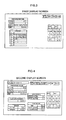
Figs. 3, 4, and 5 illustrate a first display screen, a
second display screen, and a third display screen,
respectively, of the display unit 43. The display unit 43
is, for example, a touch-panel, and some of the functions of
the input unit 39 are included in the display screens.
Referring to Fig. 3, by touching an "INPUT" key
provided on the first display screen, a numeric pad and
other function keys of the input unit 39 appear on the first
display screen so that numbers, for example, can be inputted.
The function keys include "↑" and "↓" keys for moving the
input position on the warp-specification table. Then,
according to the input position, an operator may manually
input the yarn count, the warp yarn code, or the number of
warp yarns 2 by using the numeric pad. The first display
screen also displays a yarn code list from which the
operator can choose the desired yarn code. The operator may
then input the number in the warp-specification table. When
the yarn code is inputted, the corresponding warp-yarn type
is automatically displayed in the warp-specification table.
When the input for all of the parameters of the warp-specification
table is completed, the operator may touch an
"ENTER" key of the function keys and then an "EXEC"
(execute) key provided at the top of the first display
screen. This switches the first display screen to the
second display screen shown in Fig. 4.
Referring to Fig. 4, the second display screen displays
multiple tables for the squeezing pressure, the warp
tensions, the stretch rate, and the temperatures for the
size 11 and the drying devices 18 and 19. Each table
includes at least one standard value for the corresponding
parameter. The standard values can be changed by using the
input unit 39 on the second display screen. If the operator
desires to change the standard values, he/she may touch the
"INPUT" key so that the numeric pad and the function keys
appear on the second display screen. By touching the "↑"
and "↓" keys, the input position moves on the tables.
According to the input position, the operator may input
desired numerical values by using the numeric pad. When all
of the standard values are set at desired values, the
operator may touch the "ENTER" key. Subsequently, by
touching a "MODEL NO. REGISTER" key, the operator can input
a corresponding model number in a model number section by
using the numeric pad. By touching the "ENTER" key, the
model number and its warp specifications are stored in the
model-number memory portion of the memory unit 42 such that
the final displayed values are set as the operating-condition
values.
In the second display screen, if an operator desires to
use the already-displayed values as the operating-condition
values, he/she may touch the "SET" key. On the other hand,
if he/she desires to change the displayed values partially,
he/she may touch the "INPUT" key, which causes the numeric
pad to appear. By using the numeric pad, the operator can
change the values. When all of the displayed values are set
at the desired values, the operator may touch the "ENTER"
key and then the "SET" key. A "MODEL NO. LIST" key in the
second display screen is for switching the second display
screen to the third display screen, which is shown in Fig. 5.
Referring to Fig. 5, the third display screen displays
a model-number list which includes stored model numbers and
their corresponding warp yarns, i.e. warp-yarn types and
yarn count. By touching one of the numbers that corresponds
to the desired model number under the "No." column and then
touching a "DETAILS" key, the third display screen switches
back to the second display screen.
In addition to the above-mentioned parameters, another
parameter which represents moisture percentage may
alternatively be included. Similar to the other parameters,
the moisture-percentage values may be stored in the memory
unit 42, displayed in the display unit 43, and sent to the
controller 40. The moisture-percentage values indicate the
dryness of the warp yarns 2 after the sizing and drying
processes and are derived from the following equation:
moisture percentage (%) = [100 × (weight of moisture)] / [(weight
of warp) + (weight of size) + (weight of moisture)].
A moisture-measuring unit may be provided adjacent to the
winding device 30 such that the moisture percentage of the
warp yarns 2 is measured in that position. If there is a
difference between the measured moisture percentage and the
target moisture percentage included in the operating-condition
values, the controller 40 controls the traveling
speed of the warp yarns 2, the temperatures of the drying
devices 18 and 19, or the squeezing pressure within a
predetermined range of the corresponding operating-condition
value.
Furthermore, another operating-condition parameter
which represents low-speed operation may alternatively be
included. Similar to the above, low-speed-operation values
may be stored in the memory unit 42, displayed in the
display unit 43, and sent to the controller 40. In a low-speed
operation, the warp yarns 2 travel at about 10% of the
speed of the warp yarns 2 in the normal operation. The low-speed
operation prevents the warp-sizing apparatus 1 from
stopping due to yarn breakages. For example, two sets of
operating-condition values may be provided for the stretch
rate and the squeezing pressure, one set being used for the
normal operation and the other being used for the low-speed
operation. In the low-speed operation, the squeezing
pressure is reduced since the size 11 is sufficiently
squeezed out from the warp yarns 2, and the stretch rate is
also reduced since the warp yarns 2 dry well and shrink at a
low rate.
As described above, according to the above embodiment,
each model number and its warp specifications including the
warp-yarn type, the yarn count, and the number of warp yarns
2 are registered in the memory unit 42, and each model
number and the operating-condition values for the parameters
of the model number are stored in the memory unit 42. This
means that, by just inputting a model number, the operating-condition
values corresponding to the warp specifications of
the model number can be easily read from the memory unit 42.
Alternatively, only the warp specifications and the
corresponding operating-condition values for each type of
yarn sheet may be stored in the memory unit 42, meaning that
the warp specifications do not necessarily need to be
registered with the model numbers in the memory unit 42.
Furthermore, although operating-condition values are
read from the memory unit 42 by inputting a model number and
are adjusted according to need before being sent to the
controller 40, the operating-condition values may
alternatively be sent to the controller 40 simultaneously
with the read-out of the values from the memory unit 42.
This reduces the workload of the operator, thus achieving
simple operation of the input unit 39.
Furthermore, referring to Fig. 4, in the second display
screen of the above embodiment, the display section for the
standard values of the operating conditions and the
adjusting section for the standard values, i.e. the input
unit for the operating-condition values, are provided on the
same screen, such that the operating-condition values are
input by changing the standard values. Alternatively, the
display section and the adjusting section may be shifted to
other positions on the screen, or may be provided in
separate screens in a manner such that the operator can
easily refer to the standard values when inputting numerical
values via the adjusting section. This may prevent input
errors in the operating-condition values.
Although these methods according to the present
invention are used for controlling the warp-sizing apparatus
1, the operating-condition data for the apparatus 1, for
example, may be used as feedback for a process prior to the
operation of the apparatus 1 or may be used for the weaving
process that follows.