EP1510608A2 - Verfahren zum Speichern der Betriebsbedingungen einer Vorrichtung zum Schlichten von Kettfäden sowie Verfahren zum Einstellen der Betriebsbedingungen einer Vorrichtung zum Schlichten von Ketfäden - Google Patents
Verfahren zum Speichern der Betriebsbedingungen einer Vorrichtung zum Schlichten von Kettfäden sowie Verfahren zum Einstellen der Betriebsbedingungen einer Vorrichtung zum Schlichten von Ketfäden Download PDFInfo
- Publication number
- EP1510608A2 EP1510608A2 EP04017659A EP04017659A EP1510608A2 EP 1510608 A2 EP1510608 A2 EP 1510608A2 EP 04017659 A EP04017659 A EP 04017659A EP 04017659 A EP04017659 A EP 04017659A EP 1510608 A2 EP1510608 A2 EP 1510608A2
- Authority
- EP
- European Patent Office
- Prior art keywords
- warp
- parameters
- values
- standard values
- thickness
- Prior art date
- Legal status (The legal status is an assumption and is not a legal conclusion. Google has not performed a legal analysis and makes no representation as to the accuracy of the status listed.)
- Withdrawn
Links
Images


Classifications
-
- D—TEXTILES; PAPER
- D06—TREATMENT OF TEXTILES OR THE LIKE; LAUNDERING; FLEXIBLE MATERIALS NOT OTHERWISE PROVIDED FOR
- D06B—TREATING TEXTILE MATERIALS USING LIQUIDS, GASES OR VAPOURS
- D06B23/00—Component parts, details, or accessories of apparatus or machines, specially adapted for the treating of textile materials, not restricted to a particular kind of apparatus, provided for in groups D06B1/00 - D06B21/00
- D06B23/24—Means for regulating the amount of treating material picked up by the textile material during its treatment
-
- D—TEXTILES; PAPER
- D02—YARNS; MECHANICAL FINISHING OF YARNS OR ROPES; WARPING OR BEAMING
- D02H—WARPING, BEAMING OR LEASING
- D02H5/00—Beaming machines
- D02H5/02—Beaming machines combined with apparatus for sizing or other treatment of warps
Definitions
- the present invention relates to a method for storing operating conditions of a warp-sizing apparatus and a method for setting operating conditions of a warp-sizing apparatus.
- an operator determines the operating conditions corresponding to warp-specifications by inputting values for the operating-condition parameters of the apparatus. According to this method, however, the operator must rely on, for example, his/her practical knowledge and experience for inputting the values for the operating-condition parameters.
- a first aspect of the present invention is a method for storing operating conditions of a warp-sizing apparatus (1), in which, for every type and thickness of warp (2), a memory unit (42) stores standard values for at least four parameters which include stretch rate, temperature of size, temperatures of drying devices, and squeezing pressure and equations for calculating warp tensions.
- the method is characterized in that, when starting an operation of the apparatus (1), the type and thickness of warp (2) to be sized and the number of yarns of the warp (2) are input to the apparatus (1).
- the standard values for the four parameters are read from the memory unit (42) based on the type and thickness of the warp (2), and standard values for the warp tensions are calculated based on the equations corresponding to the type and thickness of the warp (2) and based on the input number of yarns of the warp (2).
- the calculated standard values define a fifth parameter.
- the standard values of the five parameters are then displayed in a display unit (43), and each of the standard values of the five parameters is adjustable.
- a new set of the values of the five parameters different from the original set of the standard values and the corresponding warp specifications including the type, the thickness, and the number of yarns of the warp (2) are additionally stored in the memory unit (42) by sending a memory command thereto.
- the standard values and past numeral values are accumulated one after the other in the memory unit (42).
- the setting of operating conditions becomes easier from the next operation onward.
- a second aspect of the present invention is a method for setting operating conditions of the warp-sizing apparatus (1), in which, for every type and thickness of warp (2), the memory unit (42) stores standard values for at least four parameters which include the stretch rate, the temperature of the size, the temperatures of drying devices, and the squeezing pressure and the equations for calculating warp tensions.
- the method is characterized in that, when starting an operation of the apparatus (1), the type and thickness of warp (2) to be sized and the number of yarns of the warp (2) are input to the apparatus (1).
- the standard values for the four parameters are read from the memory unit (42) based on the type and thickness of the warp (2), and standard values for the warp tensions are calculated based on the equations corresponding to the type and thickness of the warp (2) and based on the input number of yarns of the warp (2).
- the calculated standard values define a fifth parameter.
- the standard values of the five parameters are then displayed in the display unit (43), and each of the standard values of the five parameters is adjustable. Thus, a new set of the values of the five parameters is sent to the controller (40) by sending a setting command thereto.
- the apparatus (1) can be controlled based on the operation-condition set values of the five parameters.
- a third aspect of the present invention is a method for setting operating conditions of the warp-sizing apparatus (1), in which, for every type and thickness of warp (2), the memory unit (42) stores standard values for at least four parameters which include the stretch rate, the temperature of the size, the temperatures of drying devices, and the squeezing pressure and the equations for calculating warp tensions.
- the method is characterized in that, when starting an operation of the apparatus (1), the type and thickness of warp (2) to be sized and the number of yarns of the warp (2) are input to the apparatus (1).
- the standard values for the four parameters are read from the memory unit (42) based on the type and thickness of the warp (2), and standard values for the warp tensions are calculated based on the equations corresponding to the type and thickness of the warp (2) and based on the input number of yarns of the warp (2).
- the calculated standard values define a fifth parameter.
- the standard values of the five parameters are then displayed in the display unit (43), and each of the standard values of the five parameters is adjustable.
- a new set of the values of the five parameters different from the original set of the standard values and the corresponding warp specifications including the type, the thickness, and the number of yarns of the warp (2) are additionally stored in the memory unit (42) to sending a memory command thereto.
- the new set of the values of the five parameters and the corresponding warp specifications are then read from the memory unit (42) and are displayed in the display unit (43). Each of the read-out values is readjustable if necessary.
- the values of the five parameters are sent to the controller (40) by sending a setting command thereto.
- the stored values of the five parameters are adjusted where necessary and are then sent to the controller (40), meaning that new values may be input and set for the five parameters while referring to the past values.
- a fourth aspect of the present invention is a method for setting operating conditions of the warp-sizing apparatus (1), in which, for every type and thickness of warp (2), the memory unit (42) stores standard values for at least four parameters which include the stretch rate, the temperature of the size, the temperatures of drying devices, and the squeezing pressure and the equations for calculating warp tensions.
- the method is characterized in that, when starting an operation of the apparatus (1), the type and thickness of warp (2) to be sized and the number of yarns of the warp (2) are input to the apparatus (1).
- the standard values for the four parameters are read from the memory unit (42) based on the type and thickness of the warp (2), and standard values for the warp tensions are calculated based on the equations corresponding to the type and thickness of the warp (2) and based on the input number of yarns of the warp (2).
- the calculated standard values define a fifth parameter.
- the standard values of the five parameters are then displayed in the display unit (43), and each of the standard values of the five parameters is adjustable.
- a new set of the values of the five parameters different from the original set of the standard values and the corresponding warp specifications including the type, the thickness, and the number of yarns of the warp (2) are additionally stored in the memory unit (42) by sending a memory command thereto.
- the new set of the values of the five parameters and the corresponding warp specifications are then read from the memory unit (42) and are displayed in the display unit (43).
- the read-out values of the five parameters are sent to the controller (40) as final set values.
- the read-out values are sent directly to the controller (40). Accordingly, the past values of the five parameters can be used effectively from the next operation onward.
- warp-yarn types types of warp
- warp yarn count warp thickness
- warp-yarn types Types of warp (warp-yarn types):
- Warp yarn count (yarn thickness)
- Yarn count selected within a range from 5 to 160 (a higher yarn-count value implies finer yarn)
- the stretch rate of the warp relies on the ratio of circumferential speeds between two rollers which are actively driven, and is represented by the equation: [(circumferential speed of a downstream roller / circumferential speed of an upstream roller) - 1] ⁇ 100 (%). Taking into consideration the fact that the warp-yarn sheet stretches while being transferred and the warp yarns shrink by being dried, this equation has been derived from prior experience and tests. Rather than performing the tension control by detecting the warp tensions, the tension control according to the stretch rate values derived from this equation is more stable and suitable.
- the stretch rate between a sizing device and one of drying devices is increased such that a greater warp tension is applied, the quality of the warp may be lowered since the elongation of the warp may be lost.
- the stretch rate between one of the drying devices and a winding device is preferably increased so as to apply greater warp tension. This achieves easier division of the dried warp-yarn sheet by a dividing rod disposed between the drying device and the winding device.
- the temperatures of the drying devices refer to temperatures of drying cylinders.
- the temperatures of the drying cylinders are controlled by on/off operations of electromagnetic on/off valves. By repeating these operations, the supply of high-pressure steam is regulated such that the temperatures are adjusted to the desired values.
- a hot-air drying device having a heat exchanger disposed in the hot-air circulation path and a drying cylinder are provided.
- the heat exchanger functions by using high-temperature steam or electric heat.
- the temperature is adjusted to the desired value.
- the temperature of size is controlled by on/off operations of an electromagnetic on/off valve. By repeating these operations, the supply of high-temperature steam to the size in a sizing tank is regulated such that the temperature of the size is adjusted to the desired value.
- the squeezing pressure allows a slave-driven roller to urge against an active-driven roller via a hydraulic cylinder.
- an effective force produced in a nip between the two rollers allows the size to penetrate into each yarn effectively and also to squeeze out excess size from each yarn. This force depends on the amount of size adhered to each yarn (amount of moisture).
- a slave-driven roller is generally coated with high-friction elastic material, such as rubber. Accordingly, for some warp-yarn types or yarn thicknesses, the adhered amount of size is not lowered even if the squeezing pressure is set higher than a predetermined value, meaning that the squeezing pressure does not necessarily need to be set at a high value.
- the squeezing pressure is set only for a second squeezing roller, the squeezing pressure may also be set for a first squeezing roller.
- stored values of five parameters corresponding to warp specifications of each type of warp can be read and displayed, and moreover, may be changed to new values. Via a setting command, the stored values may be sent directly to the controller or may be sent to the controller after being changed to new values. Alternatively, the stored values of the five parameters may be sent to the controller simultaneously with the read-out and display of the values.
- Fig. 1 illustrates the relevant components of a spun-warp sizing apparatus 1.
- a plurality of warp yarns 2 are fed from a feeding beam 3 in a sheet-like shape and are guided to a sizing device 5 via, for example, four guide rollers 4.
- the feeding beam 3 has a shaft 3a to which a braking force is applied by a braking pad 6 and a tension cylinder 7 provided for the braking pad 6. Accordingly, the warp yarns 2 at the feeding side of the apparatus 1 are pulled out such that a predetermined warp tension is applied to each yarn 2.
- This warp tension can be detected by a tension detector 8, such as a load cell, disposed adjacent to the third guide roller 4.
- the warp yarns 2 are immersed in a sizing tank 10 filled with size 11 via an immersion roller 9.
- the warp yarns 2 pass through a nip between a first sizing roller 12 and a first squeezing roller 13, and then between a second sizing roller 14 and a second squeezing roller 15.
- the warp yarns 2 are separated into two groups and are sent to a first drying device 18.
- the first sizing roller 12 and the second sizing roller 14 are driven by a sizing motor 16.
- a chain which is not shown in the drawings, is looped around the sizing rollers 12 and 14 and the sizing motor 16 to rotate the rollers 12 and 14.
- a hydraulic cylinder which is not shown in the drawings, maintains the squeezing pressure of the first squeezing roller 13 at the initial setting such that the pressure cannot be changed.
- a preset squeezing pressure of the second squeezing roller 15 can be readjusted by a squeezing cylinder 17.
- the first drying device 18 includes two sets of a drying cylinder 20, a drying cylinder 21, and a guide roller 22. Each set corresponds to one of the two groups of warp yarns 2. Each group of warp yarns 2 comes into contact with the peripheries of the drying cylinders 20 and 21 of the corresponding set and is heated to dry. The two groups merge after passing through the respective guide rollers 22 and are then sent to a second drying device 19. The merged warp yarns 2 come into contact with the peripheries of drying cylinders 23 and 24 provided in the second drying device 19, whereby a final drying process is completed.
- the drying cylinders 20 and 21 are driven by a drying motor 25.
- a chain which is not shown in the drawings, is looped around the drying cylinders 20 and 21 and the drying motor 25 such that the cylinders 20 and 21 rotate with the same circumferential speed.
- the drying cylinders 23 and 24 of the second drying device 19 are also driven by the motor 25, and similarly, another chain, which is not shown in the drawings, is looped around the drying cylinders 23 and 24 and the motor 25 such that the cylinders 23 and 24 rotate with the same circumferential speed as those of the cylinders 20 and 21.
- the warp yarns 2 are guided to a winding device 30 via a guide roller 26 and a dividing rod 27.
- the warp yarns 2 pass through a nip between a take-up roller 28 and a press roller 29, and then through a tension roller 31 and a guide roller 46 to reach a winding beam 32 around which the warp yarns 2 are wound.
- the take-up roller 28 and the winding beam 32 are respectively driven by a take-up motor 33 and a winding motor 34.
- the rotational speed of the take-up roller 28 is substantially constant, whereas the rotational speed of the winding beam 32 becomes lower as the diameter of the wound warp yarns 2 increases.
- the winding beam 32 is displaced from the winding device 30 after the winding process is completed and may be disposed in a loom to function as a loom beam for feeding the warp yarns 2.
- a warp tension applied to the warp yarns 2 at the winding side of the warp-sizing apparatus 1, that is, a winding tension applied to the warp yarns 2 can be detected by a tension detector 35, such as a load cell, disposed adjacent to the tension roller 31.
- Fig. 2 illustrates a controller 40 for the warp-sizing apparatus 1.
- the controller 40 controls the stretch rate, the temperature of the size 11, the temperatures of the drying devices 18 and 19, the squeezing pressure, and the warp tensions.
- the controller 40 receives operating-condition data from an operating-condition setting unit 41.
- the data includes, for example, standard values for the operating conditions or new values that have been readjusted and changed from the original standard values.
- the controller 40 Based on the received operating-condition data, the controller 40 performs on/off operations of electromagnetic on/off valves 36, 37, and 38 to regulate the supply of high-pressure steam 45.
- the controller 40 controls the rotational speeds of the motors 16, 25, 33, and 34, and adjusts the supply of fluid 44 to the tension cylinder 7 and to the squeezing cylinder 17.
- a memory unit 42 includes a model-number memory portion and a standard-value/equation memory portion.
- Model numbers are registered in the model-number memory portion and are categorized according to warp specifications which include types of warp yarns 2 (warp-yarn types), yarn count, and the number of warp yarns 2. Furthermore, the model-number memory portion stores the model numbers and corresponding operating-condition values for the operating-condition parameters of each model number.
- the standard-value/equation memory portion stores standard values for the operating conditions according to warp-yarn types and yarn count, and equations for calculating standard warp tensions based on warp-yarn types, yarn count, and the number of warp yarns 2.
- the operating-condition setting unit 41 is capable of reading corresponding data from the model-number memory portion and the standard-value/equation memory portion.
- An operator may input warp specifications, i.e. the warp-yarn type, the yarn count, and the number of warp yarns 2, to an input unit 39.
- the operating-condition setting unit 41 receives the data including the warp specifications from the input unit 39, the setting unit 41 reads corresponding standard values and corresponding equations for the standard warp tensions from the standard-value/equation memory portion so as to derive operating-condition values.
- the operator may input the corresponding model number to the input unit 39.
- the setting unit 41 receives the data including the model number from the input unit 39, the setting unit 41 reads the operating-condition values corresponding to the input model number from the model-number memory portion.
- the operating-condition values are then displayed in a display unit 43.
- An operator then operates the input unit 39 and determines whether to select the current operating-condition values or to make adjustments if necessary. Moreover, if necessary, an operator may operate the input unit 39 to register a model number through a memory command of the input unit 39. Thus, the registered model number and its operating-condition values for the parameters of the model number are stored in the model-number memory portion. In response to a setting command sent from the input unit 39 operated by an operator, the setting unit 41 sends the selected operating-condition values to the controller 40, and the values are displayed in the display unit 43.
- the controller 40 compares the warp tension of the warp yarns 2 detected by the tension detector 8 at the feeding side of the apparatus 1, i.e. the feeding tension, with a target warp-tension value. If there is a difference between the two tension values, the controller 40 regulates the supply of fluid 44 to the tension cylinder 7 so as to control the pressure in the cylinder 7. Accordingly, the frictional force between the shaft 3a of the feeding beam 3 and the braking pad 6 is adjusted by the cylinder 7 such that the feeding tension approximates the target warp tension.
- the controller 40 compares the winding tension of the warp yarns 2 detected by the tension detector 35 at the winding side of the apparatus 1 with a target warp-tension value. Similarly, if there is a difference between the two tension values, the controller 40 controls the rotational speed of the winding motor 34 so that the winding tension approximates the target warp tension. On the other hand, since the take-up motor 33 rotates at a constant speed, the controller 40 only needs to perform on/off operations for the motor 33.
- the rotational speed of the motor 16 is adjusted based on the stretch rate of the warp yarns 2 between the sizing device 5 and the second drying device 19, namely, between the rollers 14,15 and the drying cylinder 24.
- the rotational speed of the motor 25 is adjusted based on the stretch rate of the warp yarns 2 between the sizing device 5 and the first drying device 18, namely, between the rollers 14,15 and the drying cylinders 20, and also between the first drying device 18 and the winding device 30, namely, between the drying cylinders 20 and the rollers 28,29.
- the controller 40 when the controller 40 receives the operating-condition data from the setting unit 41, the controller 40 controls the rotational speeds of the motors 16 and 25 based on the respective target stretch rate values included in the operating-condition values of the data, whereby the stretch rate of the warp yarns 2 is correspondingly adjusted.
- the on/off operations of the electromagnetic on-off valve 36 regulate the supply of high-pressure steam 45. By repeating these operations, the temperature of the size 11 is controlled. Furthermore, the temperature of the first drying device 18, i.e. the drying cylinders 20 and 21, and the temperature of the second drying device 19, i.e. the drying cylinders 23 and 24, are controlled by the respective electromagnetic on-off valves 37 and 38. In detail, the on-off operations of the on/off valves 37 and 38 regulate the supply of high-pressure steam 45 to the respective first and second drying devices 18 and 19. By repeating these operations, the temperatures of the two drying devices 18 and 19 are controlled.
- the controller 40 detects the temperature of the size 11, the temperature of the drying cylinders 20 and 21, and the temperature of the drying cylinders 23 and 24 via respective temperature sensors 47, 48, and 49. Moreover, if there are differences between the detected temperatures and target temperature values included in the operating-condition values received from the setting unit 41, the controller 40 correspondingly performs on/off operations of the on-off valves 36, 37, and 38.
- the memory unit 42 stores equations for the warp tensions and standard values for at least four parameters which include the stretch rate, the temperature of the size 11, the temperatures of the drying devices 18 and 19, and the squeezing pressure.
- the standard values and the equations are stored according to types and thicknesses of the warp yarns 2.
- the setting unit 41 when starting an operation of the warp-sizing apparatus 1, an operator inputs the type and thickness of the warp yarns 2 and the number of warp yarns 2 included in a single yarn sheet to the input unit 39 so that a setting command is sent to the operating-condition setting unit 41.
- the setting unit 41 then reads standard values of four parameters, which correspond to the type and thickness of the warp yarns 2, from the memory unit 42.
- the setting unit 41 calculates standard values for the warp tensions, i.e. warp feeding tension and warp winding tension, based on the corresponding equations and the input number of warp yarns 2. Consequently, the standard values of five operating-condition parameters are displayed in the display unit 43.
- the standard values of these five parameters can be changed partially or completely by inputting new values.
- an operator looks at a display screen of the display unit 43 and checks the standard values of the five parameters, he/she may partially adjust the values if necessary or may completely change the values to new ones. Then, the operator may operate the input unit 39 to send a memory command to the setting unit 41. Via the setting unit 41, a corresponding model number and its warp specifications including the warp-yarn type, the yarn count, and the number of warp yarns 2 are registered in the memory unit 42, and a new set of the values of the five parameters different from the original set of the standard values are additionally stored in the memory unit 42 as the operating conditions of the model number.
- the operator may select the model number so that the values of the five parameters that correspond to the warp specifications of the model number are read from the memory unit 42. These values are then displayed in the display unit 43 and can be readjusted if necessary.
- the operator may send a setting command to the setting unit 41.
- the controller 40 receives the operating-condition values of the five parameters from the setting unit 41 and sets the values as the final target values for the operation. Consequently, the controller 40 is in a stand-by state for controlling the operation using the operating-condition values of the five parameters, i.e. the stretch rate, the temperature of the size 11, the temperatures of the drying devices 18 and 19, the squeezing pressure, and the warp tensions at the feeding and winding sides, as the target values for the operation.
- operating-condition values corresponding to the warp specifications of each model number are stored in the memory unit 42 one after the other such that the values are accumulated in the memory unit 42 as usable past data. These accumulated data can be used directly without being changed or may be adjusted if necessary.
- an operator can select the warp specifications of the warp yarns 2 to be sized, i.e. the corresponding model number of the warp yarns 2 to be sized, such that the values of the five parameters corresponding to the model number are read from the memory unit 42 and are displayed in the display unit 43. Then, the values may either be sent to the controller 40 directly or may be readjusted if necessary. In the latter case, the readjusted values are stored in the memory unit 42 and are simultaneously sent to the controller 40.
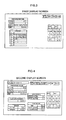
- Figs. 3, 4, and 5 illustrate a first display screen, a second display screen, and a third display screen, respectively, of the display unit 43.
- the display unit 43 is, for example, a touch-panel, and some of the functions of the input unit 39 are included in the display screens.
- a numeric pad and other function keys of the input unit 39 appear on the first display screen so that numbers, for example, can be inputted.
- the function keys include " ⁇ " and " ⁇ " keys for moving the input position on the warp-specification table.
- an operator may manually input the yarn count, the warp yarn code, or the number of warp yarns 2 by using the numeric pad.
- the first display screen also displays a yarn code list from which the operator can choose the desired yarn code. The operator may then input the number in the warp-specification table. When the yarn code is inputted, the corresponding warp-yarn type is automatically displayed in the warp-specification table.
- the operator may touch an "ENTER” key of the function keys and then an "EXEC” (execute) key provided at the top of the first display screen. This switches the first display screen to the second display screen shown in Fig. 4.
- the second display screen displays multiple tables for the squeezing pressure, the warp tensions, the stretch rate, and the temperatures for the size 11 and the drying devices 18 and 19.
- Each table includes at least one standard value for the corresponding parameter.
- the standard values can be changed by using the input unit 39 on the second display screen. If the operator desires to change the standard values, he/she may touch the "INPUT" key so that the numeric pad and the function keys appear on the second display screen. By touching the " ⁇ " and " ⁇ ” keys, the input position moves on the tables. According to the input position, the operator may input desired numerical values by using the numeric pad. When all of the standard values are set at desired values, the operator may touch the "ENTER" key.
- the operator can input a corresponding model number in a model number section by using the numeric pad.
- the model number and its warp specifications are stored in the model-number memory portion of the memory unit 42 such that the final displayed values are set as the operating-condition values.
- the second display screen if an operator desires to use the already-displayed values as the operating-condition values, he/she may touch the "SET" key. On the other hand, if he/she desires to change the displayed values partially, he/she may touch the "INPUT” key, which causes the numeric pad to appear. By using the numeric pad, the operator can change the values. When all of the displayed values are set at the desired values, the operator may touch the "ENTER” key and then the "SET” key.
- a "MODEL NO. LIST" key in the second display screen is for switching the second display screen to the third display screen, which is shown in Fig. 5.
- the third display screen displays a model-number list which includes stored model numbers and their corresponding warp yarns, i.e. warp-yarn types and yarn count.
- a model-number list which includes stored model numbers and their corresponding warp yarns, i.e. warp-yarn types and yarn count.
- moisture-percentage values may be stored in the memory unit 42, displayed in the display unit 43, and sent to the controller 40.
- a moisture-measuring unit may be provided adjacent to the winding device 30 such that the moisture percentage of the warp yarns 2 is measured in that position.
- the controller 40 controls the traveling speed of the warp yarns 2, the temperatures of the drying devices 18 and 19, or the squeezing pressure within a predetermined range of the corresponding operating-condition value.
- an operating-condition parameter which represents low-speed operation may alternatively be included. Similar to the above, low-speed-operation values may be stored in the memory unit 42, displayed in the display unit 43, and sent to the controller 40. In a low-speed operation, the warp yarns 2 travel at about 10% of the speed of the warp yarns 2 in the normal operation. The low-speed operation prevents the warp-sizing apparatus 1 from stopping due to yarn breakages.
- two sets of operating-condition values may be provided for the stretch rate and the squeezing pressure, one set being used for the normal operation and the other being used for the low-speed operation. In the low-speed operation, the squeezing pressure is reduced since the size 11 is sufficiently squeezed out from the warp yarns 2, and the stretch rate is also reduced since the warp yarns 2 dry well and shrink at a low rate.
- each model number and its warp specifications including the warp-yarn type, the yarn count, and the number of warp yarns 2 are registered in the memory unit 42, and each model number and the operating-condition values for the parameters of the model number are stored in the memory unit 42.
- only the warp specifications and the corresponding operating-condition values for each type of yarn sheet may be stored in the memory unit 42, meaning that the warp specifications do not necessarily need to be registered with the model numbers in the memory unit 42.
- operating-condition values are read from the memory unit 42 by inputting a model number and are adjusted according to need before being sent to the controller 40
- the operating-condition values may alternatively be sent to the controller 40 simultaneously with the read-out of the values from the memory unit 42. This reduces the workload of the operator, thus achieving simple operation of the input unit 39.
- the display section for the standard values of the operating conditions and the adjusting section for the standard values i.e. the input unit for the operating-condition values
- the display section and the adjusting section may be shifted to other positions on the screen, or may be provided in separate screens in a manner such that the operator can easily refer to the standard values when inputting numerical values via the adjusting section. This may prevent input errors in the operating-condition values.
- the operating-condition data for the apparatus may be used as feedback for a process prior to the operation of the apparatus 1 or may be used for the weaving process that follows.
Landscapes
- Engineering & Computer Science (AREA)
- Textile Engineering (AREA)
- Treatment Of Fiber Materials (AREA)
- Warping, Beaming, Or Leasing (AREA)
Applications Claiming Priority (2)
| Application Number | Priority Date | Filing Date | Title |
|---|---|---|---|
| JP2003291197 | 2003-08-11 | ||
| JP2003291197A JP2005060870A (ja) | 2003-08-11 | 2003-08-11 | 経糸糊付け機の運転条件の記憶方法および設定方法 |
Publications (2)
| Publication Number | Publication Date |
|---|---|
| EP1510608A2 true EP1510608A2 (de) | 2005-03-02 |
| EP1510608A3 EP1510608A3 (de) | 2005-10-05 |
Family
ID=34101133
Family Applications (1)
| Application Number | Title | Priority Date | Filing Date |
|---|---|---|---|
| EP04017659A Withdrawn EP1510608A3 (de) | 2003-08-11 | 2004-07-26 | Verfahren zum Speichern der Betriebsbedingungen einer Vorrichtung zum Schlichten von Kettfäden sowie Verfahren zum Einstellen der Betriebsbedingungen einer Vorrichtung zum Schlichten von Ketfäden |
Country Status (4)
| Country | Link |
|---|---|
| EP (1) | EP1510608A3 (de) |
| JP (1) | JP2005060870A (de) |
| KR (1) | KR20050018582A (de) |
| CN (1) | CN100340711C (de) |
Cited By (1)
| Publication number | Priority date | Publication date | Assignee | Title |
|---|---|---|---|---|
| CN115015244A (zh) * | 2022-04-22 | 2022-09-06 | 江苏欧罗曼家纺有限公司 | 基于多模态传感设备的浆纱上浆品质分析方法 |
Families Citing this family (4)
| Publication number | Priority date | Publication date | Assignee | Title |
|---|---|---|---|---|
| CN102134792B (zh) * | 2011-01-19 | 2013-02-27 | 广州纺织服装研究院 | 一种用于纱线整理的纺织设备及纱线整理方法 |
| CN102493146B (zh) * | 2011-11-26 | 2013-02-13 | 南通全技纺织涂层有限公司 | 智能型功能涂层织物涂层厚度在线检测与自适应控制装置 |
| CN115726088B (zh) * | 2022-12-16 | 2025-09-19 | 苏州汇川控制技术有限公司 | 织机经纱张力控制方法、设备、织机及可读存储介质 |
| CN117385575B (zh) * | 2023-07-27 | 2024-04-19 | 青岛天一红旗纺机集团有限公司 | 一种自动化浆纱装置 |
Family Cites Families (3)
| Publication number | Priority date | Publication date | Assignee | Title |
|---|---|---|---|---|
| JPH07122193B2 (ja) * | 1991-09-21 | 1995-12-25 | 新雄 垣中 | サイザー |
| JP2975779B2 (ja) * | 1992-09-21 | 1999-11-10 | 津田駒工業株式会社 | 経糸糊付機のストレッチ制御方法 |
| JP2002309477A (ja) * | 2001-04-17 | 2002-10-23 | Kawamoto Seiki Kk | 糊付け機における糊液濃度制御方法及び装置 |
-
2003
- 2003-08-11 JP JP2003291197A patent/JP2005060870A/ja active Pending
-
2004
- 2004-06-10 KR KR1020040042584A patent/KR20050018582A/ko not_active Withdrawn
- 2004-07-26 EP EP04017659A patent/EP1510608A3/de not_active Withdrawn
- 2004-08-11 CN CNB2004100577161A patent/CN100340711C/zh not_active Expired - Fee Related
Cited By (1)
| Publication number | Priority date | Publication date | Assignee | Title |
|---|---|---|---|---|
| CN115015244A (zh) * | 2022-04-22 | 2022-09-06 | 江苏欧罗曼家纺有限公司 | 基于多模态传感设备的浆纱上浆品质分析方法 |
Also Published As
| Publication number | Publication date |
|---|---|
| KR20050018582A (ko) | 2005-02-23 |
| EP1510608A3 (de) | 2005-10-05 |
| CN100340711C (zh) | 2007-10-03 |
| CN1580351A (zh) | 2005-02-16 |
| JP2005060870A (ja) | 2005-03-10 |
Similar Documents
| Publication | Publication Date | Title |
|---|---|---|
| RU2150537C1 (ru) | Малоинерционное положительное нитеподающее устройство для эластомерных нитей и способ подачи таких нитей | |
| EP2188422B1 (de) | Texturierungs- und verwirbelungsmaschine mit doppeltem ofen | |
| EP1510608A2 (de) | Verfahren zum Speichern der Betriebsbedingungen einer Vorrichtung zum Schlichten von Kettfäden sowie Verfahren zum Einstellen der Betriebsbedingungen einer Vorrichtung zum Schlichten von Ketfäden | |
| US4920621A (en) | Apparatus and method for finishing a traveling textile fabric web | |
| CN100587140C (zh) | 纱线质量确保方法和纱线处理设备 | |
| US6578479B2 (en) | Method of operating a web-fed rotary printing machine | |
| JPS5934808B2 (ja) | 織機並びに編機用の経糸を整経するための方法及び装置 | |
| DE102013108507B4 (de) | Wickelmaschine zum Aufwickeln von Wattenbändern zu Wattewickeln | |
| US7213310B2 (en) | Device for finishing denim woven fabric | |
| JP5965115B2 (ja) | 繊維機械のドラフトシステムおよびその運転方法 | |
| NL1024868C1 (nl) | Werkwijze en inrichting om parallelle vezels op gewenste, onderling gelijke spanning te brengen. | |
| EP0129063A2 (de) | Verfahren und Vorrichtung zum thermischen Behandeln von wärmeschrumpfbaren bandförmigen Gegenständen | |
| KR101155977B1 (ko) | 편성기와 편성기에서의 편사 가공 방법, 및편성기에서의 편사 가공 제어장치와 그 프로그램 | |
| EP1715091B1 (de) | Verfahren und Vorrichtung zum Rundstricken eines Elastomergarns mit Kompensierung der Garnkörperrelaxation | |
| US7997055B2 (en) | Method for the thermal treatment of a running yarn and twisting machine for carrying out the method | |
| US6119732A (en) | Warp thread consumption optimization apparatus for a weaving machine | |
| CN212051975U (zh) | 一种可控制纬向张力的起毛机 | |
| US4903914A (en) | Warping yarn accumulator | |
| JP2008023751A (ja) | 輪転印刷機およびその運転方法 | |
| KR102115261B1 (ko) | 편직물 제조를 위한 원사 급사 방법 및 장치 | |
| JP2663822B2 (ja) | 延伸仮撚機における仮撚装置の制御装置 | |
| JPH0149822B2 (de) | ||
| KR102900742B1 (ko) | 텐터 가공 관리 시스템 | |
| US6826931B2 (en) | Machine for processing a pair of wetted knit fabric tubes from a common control simultaneously but independently | |
| JPH08284030A (ja) | ドラフト装置 |
Legal Events
| Date | Code | Title | Description |
|---|---|---|---|
| PUAI | Public reference made under article 153(3) epc to a published international application that has entered the european phase |
Free format text: ORIGINAL CODE: 0009012 |
|
| AK | Designated contracting states |
Kind code of ref document: A2 Designated state(s): AT BE BG CH CY CZ DE DK EE ES FI FR GB GR HU IE IT LI LU MC NL PL PT RO SE SI SK TR |
|
| AX | Request for extension of the european patent |
Extension state: AL HR LT LV MK |
|
| PUAL | Search report despatched |
Free format text: ORIGINAL CODE: 0009013 |
|
| AK | Designated contracting states |
Kind code of ref document: A3 Designated state(s): AT BE BG CH CY CZ DE DK EE ES FI FR GB GR HU IE IT LI LU MC NL PL PT RO SE SI SK TR |
|
| AX | Request for extension of the european patent |
Extension state: AL HR LT LV MK |
|
| AKX | Designation fees paid | ||
| STAA | Information on the status of an ep patent application or granted ep patent |
Free format text: STATUS: THE APPLICATION IS DEEMED TO BE WITHDRAWN |
|
| 18D | Application deemed to be withdrawn |
Effective date: 20060406 |
|
| REG | Reference to a national code |
Ref country code: DE Ref legal event code: 8566 |