EP1510481A2 - Slip sheet capture mechanism and method of operation - Google Patents
Slip sheet capture mechanism and method of operation Download PDFInfo
- Publication number
- EP1510481A2 EP1510481A2 EP04104087A EP04104087A EP1510481A2 EP 1510481 A2 EP1510481 A2 EP 1510481A2 EP 04104087 A EP04104087 A EP 04104087A EP 04104087 A EP04104087 A EP 04104087A EP 1510481 A2 EP1510481 A2 EP 1510481A2
- Authority
- EP
- European Patent Office
- Prior art keywords
- slip sheet
- plate
- nip
- foot
- substrates
- Prior art date
- Legal status (The legal status is an assumption and is not a legal conclusion. Google has not performed a legal analysis and makes no representation as to the accuracy of the status listed.)
- Withdrawn
Links
Images


Classifications
-
- B—PERFORMING OPERATIONS; TRANSPORTING
- B41—PRINTING; LINING MACHINES; TYPEWRITERS; STAMPS
- B41C—PROCESSES FOR THE MANUFACTURE OR REPRODUCTION OF PRINTING SURFACES
- B41C1/00—Forme preparation
- B41C1/10—Forme preparation for lithographic printing; Master sheets for transferring a lithographic image to the forme
- B41C1/1083—Mechanical aspects of off-press plate preparation
-
- B—PERFORMING OPERATIONS; TRANSPORTING
- B65—CONVEYING; PACKING; STORING; HANDLING THIN OR FILAMENTARY MATERIAL
- B65H—HANDLING THIN OR FILAMENTARY MATERIAL, e.g. SHEETS, WEBS, CABLES
- B65H3/00—Separating articles from piles
- B65H3/02—Separating articles from piles using friction forces between articles and separator
-
- B—PERFORMING OPERATIONS; TRANSPORTING
- B65—CONVEYING; PACKING; STORING; HANDLING THIN OR FILAMENTARY MATERIAL
- B65H—HANDLING THIN OR FILAMENTARY MATERIAL, e.g. SHEETS, WEBS, CABLES
- B65H2301/00—Handling processes for sheets or webs
- B65H2301/30—Orientation, displacement, position of the handled material
- B65H2301/33—Modifying, selecting, changing orientation
- B65H2301/332—Turning, overturning
- B65H2301/3321—Turning, overturning kinetic therefor
- B65H2301/33216—Turning, overturning kinetic therefor about an axis perpendicular to the direction of displacement and to the surface of material
-
- B—PERFORMING OPERATIONS; TRANSPORTING
- B65—CONVEYING; PACKING; STORING; HANDLING THIN OR FILAMENTARY MATERIAL
- B65H—HANDLING THIN OR FILAMENTARY MATERIAL, e.g. SHEETS, WEBS, CABLES
- B65H2404/00—Parts for transporting or guiding the handled material
- B65H2404/10—Rollers
- B65H2404/14—Roller pairs
- B65H2404/142—Roller pairs arranged on movable frame
-
- B—PERFORMING OPERATIONS; TRANSPORTING
- B65—CONVEYING; PACKING; STORING; HANDLING THIN OR FILAMENTARY MATERIAL
- B65H—HANDLING THIN OR FILAMENTARY MATERIAL, e.g. SHEETS, WEBS, CABLES
- B65H2405/00—Parts for holding the handled material
- B65H2405/50—Gripping means
- B65H2405/51—Gripping means oscillating in arcuate paths
-
- B—PERFORMING OPERATIONS; TRANSPORTING
- B65—CONVEYING; PACKING; STORING; HANDLING THIN OR FILAMENTARY MATERIAL
- B65H—HANDLING THIN OR FILAMENTARY MATERIAL, e.g. SHEETS, WEBS, CABLES
- B65H2405/00—Parts for holding the handled material
- B65H2405/50—Gripping means
- B65H2405/57—Details of the gripping parts
-
- B—PERFORMING OPERATIONS; TRANSPORTING
- B65—CONVEYING; PACKING; STORING; HANDLING THIN OR FILAMENTARY MATERIAL
- B65H—HANDLING THIN OR FILAMENTARY MATERIAL, e.g. SHEETS, WEBS, CABLES
- B65H2511/00—Dimensions; Position; Numbers; Identification; Occurrences
- B65H2511/50—Occurence
- B65H2511/51—Presence
-
- B—PERFORMING OPERATIONS; TRANSPORTING
- B65—CONVEYING; PACKING; STORING; HANDLING THIN OR FILAMENTARY MATERIAL
- B65H—HANDLING THIN OR FILAMENTARY MATERIAL, e.g. SHEETS, WEBS, CABLES
- B65H2701/00—Handled material; Storage means
- B65H2701/10—Handled articles or webs
- B65H2701/18—Form of handled article or web
- B65H2701/182—Piled package
- B65H2701/1826—Arrangement of sheets
- B65H2701/18264—Pile of alternate articles of different properties, e.g. pile of working sheets with intermediate sheet between each working sheet
-
- B—PERFORMING OPERATIONS; TRANSPORTING
- B65—CONVEYING; PACKING; STORING; HANDLING THIN OR FILAMENTARY MATERIAL
- B65H—HANDLING THIN OR FILAMENTARY MATERIAL, e.g. SHEETS, WEBS, CABLES
- B65H2701/00—Handled material; Storage means
- B65H2701/10—Handled articles or webs
- B65H2701/19—Specific article or web
- B65H2701/1928—Printing plate
Definitions
- the present invention relates to a mechanism to capture a slip sheet.
- plates are typically large substrates that have been coated with photosensitive or thermally-sensitive material layers, referred to the emulsion.
- the substrates are fabricated from aluminum, although organic substrates, such as polyester or paper, are also available for smaller runs.
- Computer-to-plate printing systems are used to render digitally stored print content onto these printing plates.
- a computer system is used to drive an imaging engine of the platesetter.
- the plate is fixed to the outside or inside of a drum and then scanned with a modulated laser source in a raster fashion.
- the imaging engine selectively exposes the emulsion that is coated on the plates. After this exposure, the emulsion is developed so that, during the printing process, inks will selectively adhere to the plate's surface to transfer the ink to the print medium.
- one of two different strategies is used to feed substrates to the imaging engine in the printing system. In the simplest case, an operator manually places individual substrates into a feeder that then conveys the substrates through a feed port to the drum scanner. This approach, however, has some obvious drawbacks, since an operator must be dedicated to feeding the substrates. Moreover, the printing system must be housed within a light-safe environment, if the substrates being used have any sensitivity to ambient light. The alternative approach is to use a substrate manager.
- cassettes are loaded into the manager on a table.
- the table is then raised and lowered inside the manager to bring the substrates of a selected cassette into cooperation with a picker that grabs individual substrates and feeds them to the imaging engine.
- the invention features a slip sheet capture mechanism for a substrate processing machine. It comprises a foot for holding a portion of the slip sheet and a nip roller for engaging and drawing the slip sheet in the direction of the foot and into a nip.
- a slip sheet capture mechanism for a substrate processing machine. It comprises a foot for holding a portion of the slip sheet and a nip roller for engaging and drawing the slip sheet in the direction of the foot and into a nip.
- the foot comprises a foot frame and a friction pad on the foot frame for engaging the slip sheet.
- the nip roller draws the slip sheet into the nip by rotating in the direction of the foot a predetermined amount. This draws the slip sheet between the nip roller and a follower roller, which cooperates with the nip roller to hold the slip sheet.
- a slip sheet sensor is used to determine whether a slip sheet is under the slip sheet capture mechanism.
- the plate manager 20 comprises a plate store 200, a plate inverter system 300, a plate transfer system 400, and a plate inserter 600, all of which are controlled by a system controller 50.
- a plate imaging engine 500 is further provided to expose the substrates.
- a slip sheet handler 100 captures a slip sheet SS, that is typically located between the individual plates in the stack of plates 212 and subsequently transfers the slip sheet SS with the plate 10 over the transfer path 310. Typically, the slip sheet handler 100 then passes the slip sheets off for storage.
- the plate inverter system 300 transfers the plate 10 over the arcuate transfer path 310 from the plate picker or peeler system 216 of the plate storage system 200 to the plate transfer system 400.
- This transfer system 400 in the present implementation, comprises a conveyer 410 that receives the plate 10 and then moves the plate 10 laterally in the plate manager 20 toward the plate imaging engine 500.
- the plate inserter system 600 Between the plate imaging engine 500 and the transfer system 400 is a plate inserter system 600.
- the angle of the plate is moved from generally a horizontal orientation as it is received from the transfer system 400 to a more vertical orientation for insertion into the plate imaging engine 500. Specifically, the plate is angled at 75 degrees from horizontal for insertion into the engine.
- the plate inserter system 600 comprises an inserter transfer path 610. It moves the plate from its horizontal position as it is transferred across the conveyer 410 to a more vertical orientation. It transfers the plate 10 so that it is received by a first set of output pinch rollers 612, and transferred to a second set of pinch rollers 614.
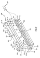
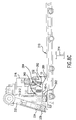
- Fig. 2 shows the present embodiment of the plate inverter system 300. It generally comprises a left lagging arm 312-L and a right lagging arm 312-R.
- the right and left lagging arms 312-R, 312-L support lagging arm nip rollers 314 and 316.
- These lagging arm nip rollers 314, 316 extend between the right and left lagging arms, parallel to each other, to thereby define a nip between the first lagging arm nip roller 314 and the second lagging arm roller 316.
- a support plate 326 is typically required. It extends between the right lagging arm 312-R and the left lagging arm 312-L, being connected to the lagging arms via L brackets 328. This increases the rigidity of the system of lagging arms 312.
- a plate lagging edge detector 354 is provided on the lagging arm system. Specifically, it is attached to the lagging arm support member 326. It projects down near a plane that extends between the nip of the first lagging arm nip roller 314 and the second lagging arm nip roller 316. In the preferred implementation, it detects the level of reflected light. As a result, it can detect whether a reflective substrate, such as a plate, is being held in the nip of the lagging arm nip rollers 314, 316. This arrangement for detecting the plate requires that the plate surface opposite the detector be reflective, which is a characteristic of the non-emulsion side of the plate.
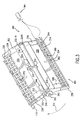
- Fig. 3 shows the plate inverter system 300 in a feed or intermediate position. Specifically, the leading arm motor 344 has been driven to rotate the right leading arm 332-R and the left leading arm 332-L upward along the arcuate transfer path 310. This view better shows the first leading arm nip roller 334 and the second leading arm nip roller 336.
- the lagging arms 312-R, 312-L further carry a first or upper air bar 360 and a second or lower air bar 362, in one embodiment. These are connected to a compressor system 364, which provides compressed air to the first air bar 360 and the second air bar 362 of the lagging arm system to facilitate the separation of slip sheets from the plates, under the control of the system controller 50.
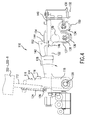
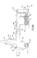
- Fig. 4 shows the slip sheet capture mechanism 110. Specifically, it comprises a first member 112 that is rigidly connected to the right and left leading arms 332-L, 332-R. A series of second members 114 are bolted to the first member 112 via bolts 116. A distal end 118 of the second member 114 has a bore through which a shaft 120 extends. The shaft 120 similarly extends through a pivot frame member 122. As a result, the pivot frame member 122 can rotate with respect to the second frame members 114. A spring member 124 is bolted to the first member 112 and spring loaded to a pivot point 126 of the pivot frame member 122. This resiliently biases the pivot frame member 122 relative to the first member 112 to rotate about shaft 120 in the direction of arrow 128.
- the slip sheet capture mechanism 110 engages a slip sheet via three components.
- the slip sheet capture mechanism has a foot frame 130 that is bolted to the end of the pivot frame member 122.
- the foot frame 130 supports a foot pad 132 for holding a slip sheet.
- the mechanism 110 further comprises a drive slip sheet roller 136 that is journaled to rotate on the pivot frame 122 via axle 138 and a slip sheet follower roller 134 that is similarly journaled to rotate relative to the pivot frame 122 that supports it.
- the drive nip roller 136 includes a gear 137 that engages an intermediate gear 139, which is also journaled to rotate on the pivot frame 122.
- Slip sheet detector probes 150 are further provided on the pivot frame 128. They extend below the outer periphery of the follower roller 134 to verify the presence or not of a slip sheet. Generally conductivity is detected between the probes. A slip sheet will be non-conductive yielding a very high resistance between the probes 150. A plate will be conductive resulting in a low resistance.
- Fig. 5 better shows the arrangement of the double acting air cylinder 142 and its rack 140. It rotates gear 139 to in turn drive the drive roller 136 via its drive roller gear 137. It allows the selective rotation of the drive roller 136.
- Fig. 6 shows a system for detecting the degree to which the pivot frame 122 is pivoting with respect to the first member 112.
- a flag arm 152 is provided, which is bolted to the first member 112. It comprises a flag portion 154 that passes in proximity to a sensor 156.
- the pivoting of the pivot frame 122 can thereby be detected by this detector 156 and specifically when the pivot frame 122 has rotated a predetermined amount such that the flag portion 154 is within the slot of the U-shaped element of the sensor 156.
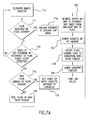
- the cassette elevator 214 raises the cassette 210.
- the cassette is also horizontally moved via the cassette translator 218.
- the leading arms 332 and the lagging arms 312 are moved out of the home position to provide clearance for the cassette's movement.
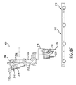
- Figs. 8A and 8B illustrate the operation of step 710. Specifically, in Fig. 8A, the leading arms 332 and the lagging arms 312 are in the home position. However, as illustrated in Fig. 8B, for the cassette 210 to be raised by the elevator 214, both the leading arms 332 and the lagging arms 312 move to provide clearance for the cassette 210. This brings the top plate in the stack of plates 212 in the cassette 210 into engagement with the peeler mechanism 216.
- the peeler mechanism 216 includes an array of suction cups 230 that are brought into engagement with the top plate in the plate stack 212.
- the height to which the cassette 210 is raised by elevator 214 is controlled by feedback from sensor probe 232 that functions as a plate stack height detector. It engages or contacts and thus detects the top plate to thereby control the height of the plate/cassette such that the suction cups 230 can engage the top plate. It should be noted that since the stack 212 in the cassette 210 can contain a variable number of plates, the elevator could not simply raise the cassette 210 to a fixed height, thus leading to the requirement of the stack height detector 232. Also provided is a pair of conductive springs 231 that make contact with the non-emulsion side of the plate. The springs 231 are compliant so as to not damage the non-emulsion side of the plate. The electrical continuity between the springs 231 signifies whether a plate is present. This conductivity test determines whether it is in contact with a plate. Plates are typically metal and therefore conductive, whereas a slip sheet or the bottom of the cassette is non-conductive.
- the plate sensor 231 detects the presence of a plate.
- vacuum is provided to the suction cup array 230 in step 714 to engage with the plate.
- the elevator 214 continues to raise the cassette until the plate stack height detector 232 detects the plate stack at the proper height in step 712 and to ensure plate contact with suction cups.
- step 716 it is determined whether a plate is detected. If the conductive springs 231 do not detect a plate before the sensor probe 232 activates the plate stack height detector, this indicates that contact has been made with a non-conductive surface. This implies that cardboard at the bottom of the cassette or the cassette bottom has been detected, and the cassette is empty of plates, as determined in step 718. Alternatively, it may also indicate that a slip sheet is present, which would lead to an error condition or the activation of the slip sheet removal system to remove the slip sheet.
- the plate is peeled up by the action of the suction cup array 230 pivoting around pivot point 282 in the clockwise direction of arrow 215 in step 720 (see Fig. 8A).
- pressurized air is also provided to the first air bar 360 in step 722.
- the air bar has a series of holes spaced along the length and is rotationally aligned to optimize the direction of air flow to separate the slip sheet from the emulsion side or the bottom of the peeled plate. This action is illustrated in Fig. 8B.
- activation of the air bar can be avoided in situations in which slip sheet-plate separation occurs predictably without such facilitation.
- step 724 the cassette 210 is lowered by the elevator 214.
- the peeler mechanism 216 rotates about pivot point 282 in the counterclockwise direction, see arrow 284, in Fig. 8C.
- the leading edge 10-L of the plate 10 is thereby moved to a horizontal position in step 726.
- the cassette is lowered another set or predetermined amount in step 728 to provide clearance to the leading and lagging arms.
- the leading arm 332 and the lagging arm 312 begin to be rotated back to their home position as shown in Fig. 8C.
- the lagging arm nip actuation mechanism 330 is also actuated in step 730 so that the nip between the first and second lagging arm rollers 314, 316 is opened.
- the lagging arms 312 are then rotated fully to the home position to receive the plate 10, which is being handed off from the peeler 216, in step 732.
- the lagging arm drive roller 314 is rotated to aid in the introduction of the plate leading edge into the nip of the rollers 312, 314.
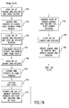
- Fig. 8C The configuration is shown in Fig. 8C.
- the plate header 10-L is being held up by the suction cup array 230 so that the header extends into the nip between nip rollers 314, 316.
- a flexible electrostatic discharge member 281 that makes electrical contact with the non-emulsion side of the plate.
- the member 281 is connected to electrical ground.
- member 281 is a chain. This discharges any electrostatic charge on the plate 10.
- step 734 the lagging arm nip actuation mechanism 330 is activated to close the nip between the first and second nip rollers 314, 316 of the lagging arms 312 and the lagging drive roller 314 rotation is stopped.
- step 736 the vacuum to the suction cup array 230 is removed and the peeler mechanism 216 rotates out of engagement with the plate 10.
- step 738 the leading arm nip actuation mechanism 338 is activated to open the nip between the first and second leading arm nip rollers 334, 336. The leading arms 332 are then rotated to the home position in step 740.
- step 742 the slip sheet is captured.
- Fig. 8D shows the process for capturing the slip sheet SS.
- the raising of the cassette 210 by the elevator 214 causes the top slip sheet to engage the foot pad 132 of the foot 130.
- the pivot frame 122 continues rising of the cassette by the elevator causes the pivot frame 122 to rotate in the direction of arrow 128' around shaft 120.
- This causes the stationary interrupt flag 154 of the rotating flag arm 152 to be detected by the elevation control sensor 156, which is attached to the pivot frame 122 is best illustrated in Fig. 6.
- the elevator 214 is controlled to cease to raise the cassette 210 by the controller 50.
- the pivot frame 122 is biasing the foot pad 132 against the top slip sheet SS, pinning it against the stack of plates beneath the slip sheet in the cassette.
- the drive roller 136 is also in contact with the slip sheet SS, but the follower roller 134 does not contact the slip sheet in the cassette.
- the slip sheet capture mechanism is activated.
- the double acting air cylinder 142 is activated by a solenoid to move the rack 140 to rotate gear 139.
- Gear 139 is meshed with gear 137 which is attached to roller 136.
- the limited motion of rack 140 in turn rotates roller 136 through a predetermined angle.
- Fig. 8D shows the path of the slip sheet SS during slip sheet capture.
- follower roller 134 forced by spring 121, is in contact with roller 136. This allows roller 136 and 134 to rotate together as best illustrated by Fig. 4. With foot 132 and roller 136 in contact with the slip sheet SS, rotation of roller 136 forces slip sheet SS toward the foot 132 with the foot 132 holding the slip sheet in place. The slip sheet is thus forced upward into the nipped rollers 136, 134 as indicated by path A, in Fig. 8D.
- the pressurized air is optionally provided to the second air bar 362 to minimize adhesion between the slip sheet and the emulsion side of the plate 10.
- the plate 10 is then advanced by driving the lagging arm nip rollers 314, 316 until the plate header is detected between the first and second leading arm nip rollers 334, 336 by the plate header detector 370. This detection occurs in step 746.
- the leading arm nip actuation mechanism closes the nip between the leading arm nip rollers 334 and 336 in step 748. So, with plate 10 being held by the plate inverter system 300 and the slip sheet SS being held by the slip sheet capture mechanism 110, the cassette 210 is lowered further by the elevator 214. The leading arms 332 are then rotated to draw the header 10-A of the plate 10 toward the plate transfer system 400, in step 750. In concert, the lagging arm nip rollers 314 and 316 are driven to feed the plate. This is shown in Fig. 8E, where the plate 10 makes an arc through the arcuate transfer path between the leading arms 332 and the lagging arms 312.
- the transfer system 400 is configured to receive the plate header 10A.
- nip rollers in the transfer system 400 are opened when the leading arms are at 170 degrees.
- step 762 the lagging arm nip rollers 314, 316 continue to rotate, while the leading arms 332 rotate through the arcuate transfer path 310.
- the lagging arm nip rollers 314, 316 slightly over-feed the plate 10 to ensure that the plate forms an arc through the arcuate transfer path 310. This prevents any sharp bending or binding of the plate, and prevents the plate from being tugged by the leading arms 332..
- step 764 the controller 50 determines whether the motor encoder count associated with the lagging arm nip actuation and roller drive mechanism 330 corresponds or is nearly equal to the length of the plate 10. That is, the rollers 314, 316 have almost entirely fed the plate 10. This state is illustrated in Fig. 8E.
- the plate header 10A is being brought into proximity to the transfer system 400 and the plate tail or trailing end 10B is being held in the nip of lagging arm rollers 314, 316.
- slip sheet SS is handed off to slip sheet storage, in preferred embodiment. This typically involves its ejection by the slip sheet capture mechanism 110.
- step 766 the lagging arm rollers 314, 316 stop rotating to hold the tail 10B of the plate 10 and the lagging arms 312 rotate through the transfer path 310.
- both the leading arms 332 and the lagging arms 312 are rotating, moving the plate through path 310.
- the leading arms carry the leading edge 10A of the plate to the plate transfer system 400.
- the nip rollers of the lagging arms feed the plate 10 until the lagging edge of the plate 10 is detected or determined to be present, at which time the nip rollers 314, 316 of the lagging arm 312 cease to drive and instead, the lagging arms 312 begin to follow the leading arms 332 through the arcuate transfer path 310.
- the upper nip rollers 314, in contact with the non-emulsion side of the plate is under motor control for several reasons.
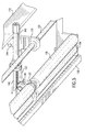
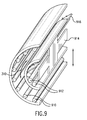
- Fig. 9 shows another embodiment of the plate inverter 300.
- two opposed races of rollers 910 and 912 are journaled to a two-sided arcuate frame 914 that defines the arcuate transfer path 310.
- the rollers 910 and 912 freely rotate to enable a plate to move along this transfer path 310.
- the outer race of rollers 910 in combination with the inner race of rollers 912 maintain the radius of the plate while a carrier 916 pulls the plate header through the path 310.
Landscapes
- Engineering & Computer Science (AREA)
- Mechanical Engineering (AREA)
- Manufacturing & Machinery (AREA)
- Sheets, Magazines, And Separation Thereof (AREA)
- Exposure And Positioning Against Photoresist Photosensitive Materials (AREA)
- Registering Or Overturning Sheets (AREA)
- Delivering By Means Of Belts And Rollers (AREA)
- Feeding Of Articles By Means Other Than Belts Or Rollers (AREA)
Abstract
Description
Claims (16)
- A slip sheet capture mechanism, the slip sheet capture mechanism comprising:a foot for holding a portion of the slip sheet; anda nip roller for engaging and drawing the slip sheet in the direction of the foot and into a nip.
- A slip sheet capture mechanism as claimed in claim 1, wherein the foot comprises:a foot frame; anda friction pad on the foot frame for engaging the slip sheet.
- A slip sheet capture mechanism according to anyone of the previous claims, wherein the nip roller draws the slip sheet into the nip by rotating in the direction of the foot a predetermined amount.
- A slip sheet capture mechanism according to anyone of the previous claims, further comprising a follower roller for cooperating with the nip roller to hold the slip sheet.
- A slip sheet capture mechanism according to anyone of the previous claims, further comprising a slip sheet sensor for determining whether a slip sheet is under the slip sheet capture mechanism.
- A slip sheet capture mechanism according to anyone of the previous claims, further comprising a pivot frame for supporting the foot and the nip roller, the frame pivoting upward in response to engagement with a stack of plates including a slip sheet to thereby urge the foot into engagement with the slip sheet.
- A slip sheet capture mechanism according to claim 6, further comprising a pivot detector for determining angular movement of the pivot frame.
- A slip sheet capture mechanism according to anyone of the previous claims, further comprising a frame for supporting the foot and the nip roller, the frame being connected to a substrate transfer system so that the slip sheet is moved with the substrate from a stack of substrates.
- A method for capturing a slip sheet, the method comprising:holding a portion of the slip sheet with a foot; andengaging and drawing the slip sheet in the direction of the foot and into a nip.
- A method as claimed in claim 9, wherein the step of holding the portion of the slip sheet comprises urging a foot against the slip sheet.
- A method according to anyone of the claims 9 to 10, wherein the step of engaging and drawing the slip sheet comprises urging a nip roller into engagement with the slip sheet and then rotating the nip roller in the direction of the foot.
- A method according to anyone of the claims 9 to 11, wherein the step of engaging and drawing the slip sheet further comprises drawing the slip sheet into a nip formed between the nip roller and a follower roller.
- A method according to claim 12, further comprising, after drawing the slip sheet into the nip, extracting the slip sheet from a stack of substrates.
- A method according to claim 13, further comprising expelling the slip sheet from the nip after extraction from the stack of substrates.
- A method according to anyone of the claims 13 to 14, wherein the step of extracting the slip sheet is performed in concert with an extraction of a substrate from the stack of substrates.
- A method according to anyone of the claims 9 to 15, further comprising detecting a presence of a slip sheet.
Applications Claiming Priority (2)
| Application Number | Priority Date | Filing Date | Title |
|---|---|---|---|
| US10/649,560 US6929257B2 (en) | 2003-08-26 | 2003-08-26 | Slip sheet capture mechanism and method of operation |
| US649560 | 2003-08-26 |
Publications (2)
| Publication Number | Publication Date |
|---|---|
| EP1510481A2 true EP1510481A2 (en) | 2005-03-02 |
| EP1510481A3 EP1510481A3 (en) | 2010-12-22 |
Family
ID=34104680
Family Applications (1)
| Application Number | Title | Priority Date | Filing Date |
|---|---|---|---|
| EP04104087A Withdrawn EP1510481A3 (en) | 2003-08-26 | 2004-08-26 | Slip sheet capture mechanism and method of operation |
Country Status (3)
| Country | Link |
|---|---|
| US (1) | US6929257B2 (en) |
| EP (1) | EP1510481A3 (en) |
| JP (1) | JP2005067897A (en) |
Cited By (1)
| Publication number | Priority date | Publication date | Assignee | Title |
|---|---|---|---|---|
| EP1862413A1 (en) * | 2006-06-01 | 2007-12-05 | Punch Graphix International N.V. | A gripping unit and a method for gripping a paper |
Families Citing this family (9)
| Publication number | Priority date | Publication date | Assignee | Title |
|---|---|---|---|---|
| US7322923B2 (en) * | 2005-06-17 | 2008-01-29 | Systec Corporation | Dunnage sheet removal apparatus |
| US7396009B2 (en) * | 2005-09-19 | 2008-07-08 | Lexmark International Inc. | Method and device for correcting pick timing in an image forming device |
| US20080150223A1 (en) * | 2005-12-08 | 2008-06-26 | Todd Kepple | High speed plate pick up device |
| US20080179002A1 (en) * | 2007-01-30 | 2008-07-31 | Gromadzki Jo A L | Method and apparatus for separating a slip-sheet from an image recordable material |
| US7604231B2 (en) * | 2007-01-30 | 2009-10-20 | Eastman Kodak Company | Method and apparatus for separating media combinations from a media stack |
| US7614619B2 (en) * | 2007-01-30 | 2009-11-10 | Eastman Kodak Company | Methods and apparatus for separating image recordable materials from a media stack |
| US7744078B2 (en) * | 2007-01-30 | 2010-06-29 | Eastman Kodak Company | Methods and apparatus for storing slip-sheets |
| US7891655B2 (en) * | 2009-04-06 | 2011-02-22 | Eastman Kodak Company | Separating media combination from a media stack |
| DE102010011196A1 (en) * | 2010-03-11 | 2011-09-15 | Heidelberger Druckmaschinen Ag | Method and device for providing and transferring printing plates |
Family Cites Families (34)
| Publication number | Priority date | Publication date | Assignee | Title |
|---|---|---|---|---|
| US308285A (en) * | 1884-11-18 | Alonzo sedgwick | ||
| GB1271526A (en) * | 1969-06-12 | 1972-04-19 | Gestetner Ltd | Improvements in or relating to sheet feeding devices |
| FR2231221A5 (en) * | 1973-05-23 | 1974-12-20 | Cit Alcatel | Device to remove sheets from top of pile - has rollers turning in both directions to free top sheet and draw it from pile |
| US4160234A (en) * | 1976-03-29 | 1979-07-03 | Gould Inc. | Abnormal tire condition sensing system |
| US4082455A (en) | 1977-06-02 | 1978-04-04 | Sun Chemical Corporation | Plate making system |
| US4260234A (en) | 1979-06-25 | 1981-04-07 | Autologic, Inc. | Media transporter for phototypesetter-processor |
| JPS56108641A (en) * | 1980-01-31 | 1981-08-28 | Nec Corp | Paper leaf detecting device |
| JPS57141334A (en) * | 1981-02-27 | 1982-09-01 | Fuji Xerox Co Ltd | Misgripping detecting device |
| IT8319476A0 (en) * | 1982-04-01 | 1983-02-08 | Rockwell Rimoldi Spa | DEVICE FOR PICKING STACKED PIECES OF OS SIMILAR TEXTILE MATERIAL. |
| GB2117739B (en) * | 1982-04-01 | 1985-09-11 | Rockwell Rimoldi Spa | Grasping device for pieces of textile material or the like piled up to form a pack |
| JPS59102733A (en) * | 1982-12-04 | 1984-06-13 | Ricoh Co Ltd | Paper feed device |
| DE3520890A1 (en) * | 1985-06-11 | 1986-12-11 | Alois Zettler Elektrotechnische Fabrik GmbH, 8000 München | DEVICE FOR PULLING LEAFS FROM A PILE PACK |
| JP2521255B2 (en) * | 1986-01-27 | 1996-08-07 | 松下電工株式会社 | Method and apparatus for alternately stacking sheet material and veneer |
| DK165527C (en) | 1990-03-22 | 1993-04-26 | Eskofot As | METHOD AND APPARATUS FOR SINGLE-SHIPPING OFFSET PRINTING PLATES |
| DE4121190A1 (en) * | 1990-06-28 | 1992-01-30 | Juki Kk | DEVICE FOR SEPARATING AND DETECTING STACKED SHEETS |
| US5181708A (en) * | 1990-07-20 | 1993-01-26 | Compaq Computer Corporation | Method and apparatus for selecting a single sheet of paper from a paper tray |
| JPH04286553A (en) * | 1991-03-15 | 1992-10-12 | Tokyo Autom Mach Works Ltd | Paper feeding device |
| US5303910A (en) * | 1992-09-10 | 1994-04-19 | Tice Engineering & Sales, Incorporated | Pick-up means for use with limp sheet material |
| US5324016A (en) * | 1993-09-13 | 1994-06-28 | Fruit Of The Loom | Self-adjusting fabric ply picking device |
| IL110467A (en) | 1994-07-26 | 1996-07-23 | Scitex Corp Ltd | Automatic plate feeding system and method |
| JP3375760B2 (en) | 1994-11-18 | 2003-02-10 | 理想科学工業株式会社 | Transfer device |
| US5657692A (en) | 1995-05-04 | 1997-08-19 | Presstek, Inc. | Removable supply and uptake assemblies for lithographic plate material |
| US6130702A (en) | 1995-07-28 | 2000-10-10 | Creo Products Inc. | Method for reliable loading of unexposed printing plates |
| US5738014A (en) | 1996-07-31 | 1998-04-14 | Agfa Division, Bayer Corporation | Method and apparatus for making lithographic printing plates in an automated computer to plate imaging system |
| US5655452A (en) | 1996-08-07 | 1997-08-12 | Agfa Division, Bayer Corp. | Method and apparatus for an automated plate handler with slip sheet removal mechanism |
| US5809360A (en) | 1996-08-07 | 1998-09-15 | Agfa Division - Bayer Corporation | Cassette for storing and accessing plates within an automated plate handler |
| US6289650B1 (en) | 1998-05-07 | 2001-09-18 | Fuji Photo Film Co., Ltd. | Automatic plate making machine equipped with photosensitive printing plate supplying apparatus and printing plate packaging means |
| DE19906304A1 (en) * | 1999-02-15 | 2000-08-17 | Hans Peter Braun | Process is for separating textile parts which are stacked |
| JP4102540B2 (en) | 2000-10-25 | 2008-06-18 | 富士フイルム株式会社 | Sheet-fed method of plate-like member |
| US6554337B2 (en) * | 2000-12-07 | 2003-04-29 | Homayoon Kazerooni | Mechanical grapple for grabbing and holding sacks and bags |
| US6488277B2 (en) * | 2001-03-19 | 2002-12-03 | Hewlett-Packard Company | Sheet separation mechanism |
| JP2003015312A (en) * | 2001-07-03 | 2003-01-17 | Fuji Photo Film Co Ltd | Printing plate sorting transport apparatus |
| JP2003012165A (en) * | 2001-07-04 | 2003-01-15 | Fuji Photo Film Co Ltd | Slip sheet removing mechanism for printing plate sheet conveying device |
| US6688591B2 (en) * | 2002-04-05 | 2004-02-10 | Agfa Corporation | Apparatus and method for removing slip sheets |
-
2003
- 2003-08-26 US US10/649,560 patent/US6929257B2/en not_active Expired - Fee Related
-
2004
- 2004-08-19 JP JP2004239805A patent/JP2005067897A/en active Pending
- 2004-08-26 EP EP04104087A patent/EP1510481A3/en not_active Withdrawn
Cited By (2)
| Publication number | Priority date | Publication date | Assignee | Title |
|---|---|---|---|---|
| EP1862413A1 (en) * | 2006-06-01 | 2007-12-05 | Punch Graphix International N.V. | A gripping unit and a method for gripping a paper |
| US7594648B2 (en) | 2006-06-01 | 2009-09-29 | Punch Graphix International N.V. | Gripping unit and a method for gripping a paper |
Also Published As
| Publication number | Publication date |
|---|---|
| JP2005067897A (en) | 2005-03-17 |
| US6929257B2 (en) | 2005-08-16 |
| EP1510481A3 (en) | 2010-12-22 |
| US20050046105A1 (en) | 2005-03-03 |
Similar Documents
| Publication | Publication Date | Title |
|---|---|---|
| JP2003015312A (en) | Printing plate sorting transport apparatus | |
| US6929257B2 (en) | Slip sheet capture mechanism and method of operation | |
| US6823791B1 (en) | Plate inverter for plate management system and method of operation | |
| JP2001213538A (en) | Printing plate suction conveyer | |
| JP2002316736A (en) | Printing plate sheet feeder | |
| US4568073A (en) | Paper handling apparatus for a copier | |
| US7614619B2 (en) | Methods and apparatus for separating image recordable materials from a media stack | |
| EP1637323A1 (en) | Plate inverter for plate management system and method of operation | |
| US6935238B2 (en) | Image recording material conveying device and automatic image recording system | |
| JP3085909B2 (en) | Paper ejection device of image forming apparatus | |
| EP0900752A2 (en) | Foil remover with improved gripper | |
| JP2003012165A (en) | Slip sheet removing mechanism for printing plate sheet conveying device | |
| JP2003285941A (en) | Printing plate conveying device | |
| US7475875B2 (en) | Apparatus and method for separating printing plates | |
| EP0110649B1 (en) | Paper handling apparatus for a copier | |
| JP3105217B1 (en) | Plate making equipment | |
| EP1435289A1 (en) | Plate registering system and method of operation | |
| JP3967937B2 (en) | Image recording device | |
| JP3807578B2 (en) | Plate material supply equipment | |
| JP3498936B2 (en) | Plate supply device | |
| JPS63143168A (en) | Sheet stacker | |
| JP2001151360A (en) | Sucking and conveying device for printed form | |
| US6886825B2 (en) | Plate handling system | |
| JP2005239326A (en) | Sheet material feeder | |
| JP2003285942A (en) | Printing plate conveying device |
Legal Events
| Date | Code | Title | Description |
|---|---|---|---|
| PUAI | Public reference made under article 153(3) epc to a published international application that has entered the european phase |
Free format text: ORIGINAL CODE: 0009012 |
|
| AK | Designated contracting states |
Kind code of ref document: A2 Designated state(s): AT BE BG CH CY CZ DE DK EE ES FI FR GB GR HU IE IT LI LU MC NL PL PT RO SE SI SK TR |
|
| AX | Request for extension of the european patent |
Extension state: AL HR LT LV MK |
|
| PUAL | Search report despatched |
Free format text: ORIGINAL CODE: 0009013 |
|
| AK | Designated contracting states |
Kind code of ref document: A3 Designated state(s): AT BE BG CH CY CZ DE DK EE ES FI FR GB GR HU IE IT LI LU MC NL PL PT RO SE SI SK TR |
|
| AX | Request for extension of the european patent |
Extension state: AL HR LT LV MK |
|
| STAA | Information on the status of an ep patent application or granted ep patent |
Free format text: STATUS: THE APPLICATION IS DEEMED TO BE WITHDRAWN |
|
| AKY | No designation fees paid | ||
| REG | Reference to a national code |
Ref country code: DE Ref legal event code: R108 |
|
| 18D | Application deemed to be withdrawn |
Effective date: 20110301 |
|
| REG | Reference to a national code |
Ref country code: DE Ref legal event code: R108 Effective date: 20110831 |