EP1508729B1 - Faltenbalg - Google Patents
Faltenbalg Download PDFInfo
- Publication number
- EP1508729B1 EP1508729B1 EP04014788A EP04014788A EP1508729B1 EP 1508729 B1 EP1508729 B1 EP 1508729B1 EP 04014788 A EP04014788 A EP 04014788A EP 04014788 A EP04014788 A EP 04014788A EP 1508729 B1 EP1508729 B1 EP 1508729B1
- Authority
- EP
- European Patent Office
- Prior art keywords
- fold
- relief
- bellows
- terminating
- piece
- Prior art date
- Legal status (The legal status is an assumption and is not a legal conclusion. Google has not performed a legal analysis and makes no representation as to the accuracy of the status listed.)
- Expired - Lifetime
Links
- 239000000463 material Substances 0.000 claims abstract description 5
- 239000013013 elastic material Substances 0.000 claims description 3
- 238000005096 rolling process Methods 0.000 claims description 2
- 238000005452 bending Methods 0.000 abstract 1
- 230000002028 premature Effects 0.000 description 4
- 238000009825 accumulation Methods 0.000 description 1
- 238000000071 blow moulding Methods 0.000 description 1
- 238000005336 cracking Methods 0.000 description 1
- 230000001419 dependent effect Effects 0.000 description 1
- 238000011161 development Methods 0.000 description 1
- 230000018109 developmental process Effects 0.000 description 1
- 238000004519 manufacturing process Methods 0.000 description 1
- 238000007789 sealing Methods 0.000 description 1
- 210000003857 wrist joint Anatomy 0.000 description 1
Images


Classifications
-
- F—MECHANICAL ENGINEERING; LIGHTING; HEATING; WEAPONS; BLASTING
- F16—ENGINEERING ELEMENTS AND UNITS; GENERAL MEASURES FOR PRODUCING AND MAINTAINING EFFECTIVE FUNCTIONING OF MACHINES OR INSTALLATIONS; THERMAL INSULATION IN GENERAL
- F16J—PISTONS; CYLINDERS; SEALINGS
- F16J3/00—Diaphragms; Bellows; Bellows pistons
- F16J3/04—Bellows
- F16J3/041—Non-metallic bellows
- F16J3/043—Non-metallic bellows with particular means for limiting wear
Definitions
- the invention relates to a bellows according to the preamble of patent claim 1.
- Bellows are known from EP 0 940 595 A1. They consist essentially of a rotationally symmetrical body of rubber-elastic material in which a plurality of folds are formed in the longitudinal direction. Bellows, for example, serve to seal homokinetic joints, e.g. the sealing of drive shaft joints in motor vehicles.
- the final fold is the last crease in front of the connection collar due to the limited space only half and runs at the highest point directly into the connection collar, so that the final fold in the radial direction not over the connection collar protrudes.
- the flexibility of the last fold is limited and at large joint deflections of the bellows is heavily stressed at this point.
- the invention has for its object to develop a bellows of the type mentioned above such that premature wear in the final fold or the end piece is avoided and the bellows has a long service life, even with large joint deflections.
- the final fold comprises at least one longitudinally extending, rolling-bellows-shaped relief fold with a fold valley and two pleat tips which are arranged within the axial extent of the end fold and / or on the front side, on the end face of the final fold associated with the connection piece.
- the relief fold increases the flexibility of the bellows with a large deflection of a wrist joint to be protected, since the relief fold allows additional expansion of the bellows. This reduces the tensions that act on the last fold. Premature wear in the area of the final fold and the connection piece is avoided.
- the fold valley of the relief fold can be made rounded. Due to the curves, stress peaks occurring in large folds in the folding valley of the relief fold degraded, which lead in the prior art to cracking of the material and thus premature wear avoided.
- the pleat tips of the relief fold can be rounded.
- stress peaks occurring in the case of large deflections are reduced in the pleat tips of the relief fold, which in the prior art can likewise lead to tearing and premature wear.
- rounding the pleat tips the risk of buckling of the relief crease is reduced, since an accumulation of material in the pleat tip is avoided, whereby the expansion paths on the inside and outside of the relief crease is reduced when the relief crease is stretched.
- the radial depth of the relief crease between fold valley and the axially adjacent pleat tips on both sides can be 1 to 4 mm. These dimensions are matched to the typical wall thickness of a bellows. which is usually about 1 mm. Relief folds with a depth of 1 to 4 mm take advantage of the available space and provide sufficient room for expansion.
- the rounding radii of fold valley and / or pleat tips can be 0.2 to 2 mm. With these radii of curvature, the stress peaks are reduced in the case of large joint deflections of an axle joint, with at the same time sufficient usable expansion travel.
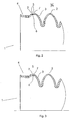
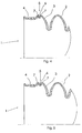
- Figures 1 to 5 differ in each case only in the form and the arrangement of the relief folds.
- Figure 1 shows a conically shaped bellows 1 for protecting a homokinetic joint of a motor vehicle, comprising four folds 2 and on a front side 8 of the bellows 1 a half executed final fold 3.
- the folds 2, 3 allow a change in length of the bellows 1 in the axial Direction as well as a gimbal deflection movement.
- the final fold 3 is connected on its side facing away from the fold 2 axially with a closure piece 4 for fastening the bellows 1 with a (not shown) machine element.
- the bellows 1 is made of the same material and in one piece and made of rubber-elastic material by blow molding.
- the wall thickness of the bellows 1 is 1 to 2 mm in this embodiment.
- a rolling bellows-shaped relief fold 5 is integrated, wherein the radial depth of the relief fold of fold tip 7 to fold valley 6 is four mm.
- the pleat tips 7 of the relief crease 5 are made rounded to reduce stress peaks occurring at large diffractions.
- the relief crease 5 allows for larger inflections of the bellows 1 a larger expansion path of the final fold.
- Figure 1 a the bellows is shown as a view.
- Figure 1b shows the bellows of Figure 1 a in longitudinal section.
- the relief folds 5 are arranged in the embodiment of Figure 2 between the final fold 3 and the end piece 4. Since the radial depth of the relief creases 5 is small due to the limited space there, two relief creases 5 are executed in order to achieve the largest possible elongation despite the small depth of the relief creases 5.
- the pleat tips 7 of the relief pleats 5 are not higher than the final pleat 3 in the radial direction.
- a bellows 1 is shown, wherein in each case only one relief fold 5 is formed.
- the depth of the relief fold 5 of fold tip 7 to fold valley 6 is sufficiently large to allow for large flexes of the bellows 1 sufficient stretching.
- a bellows 1 is shown, in which the relief fold 5 between the end fold 3 and end piece 4 is arranged.
- the depth of the relief fold 5 is larger in this embodiment than the relief fold of Figure 2.
- the pleat tips 7 are not rounded, which simplifies the manufacture of the tool for the bellows 1.
- the relief fold 5 of the embodiment of Figure 4 is seconded between final fold 3 and end piece 4.
- the depth of the relief crease 5 in this embodiment is greater than the relief crease according to FIG. 2.
- the pleat tips 7 are made rounded, as a result of which stress peaks occurring at high strains are reduced.
- Figure 5 shows a bellows 1 with a relief Weglt 5, which is seconded between final fold 3 and end piece 4.
- the depth of the relief crease 5 is greater than the relief crease of Figure 2.
- the pleat tips 7 are designed semicircular, thereby occurring at high strains stress peaks are reduced and reduces the risk of buckling of the relief crease 5 at high strains, thereby increasing the service life.
Landscapes
- Engineering & Computer Science (AREA)
- General Engineering & Computer Science (AREA)
- Mechanical Engineering (AREA)
- Diaphragms And Bellows (AREA)
- Sealing Devices (AREA)
- Tables And Desks Characterized By Structural Shape (AREA)
- Optical Communication System (AREA)
Description
- Die Erfindung betrifft einen Faltenbalg gemäß dem Oberbegriff des Patentanspruchs 1.
- Faltenbälge sind aus der EP 0 940 595 A1 bekannt. Sie bestehen im Wesentlichen aus einem rotationssymmetrischen Körper aus gummielastischem Werkstoff in dem in Längsrichtung mehrere Falten ausgeformt sind. Faltenbälge dienen beispielsweise der Abdichtung von homokinetischen Gelenken, z.B. der Abdichtung von Antriebswellen-Gelenken bei Kraftfahrzeugen.
- Bei neueren Entwicklungen wird die Abschlussfalte als letzte Falte vor dem Anschlussbund aufgrund des beschränkten Bauraums nur noch halb ausgeführt und geht an der höchsten Stelle direkt in den Anschlussbund über, so dass die Abschlussfalte in radialer Richtung nicht über den Anschlussbund hinausragt. Dadurch ist die Flexibilität der letzten Falte eingeschränkt und bei großen Gelenkbeugungen wird der Faltenbalg an dieser Stelle stark beansprucht.
- Der Erfindung liegt die Aufgabe zugrunde, einen Faltenbalg der oben genannten Art derart weiterzuentwickeln, dass vorzeitiger Verschleiß im Bereich der Abschlussfalte oder dem Abschlussstück vermieden wird und der Faltenbalg auch bei großen Gelenkbeugungen eine lange Gebrauchsdauer hat.
- Diese Aufgabe wird erfindungsgemäß mit den Merkmalen von Anspruch 1 gelöst. Auf vorteilhafte Ausgestaltungen nehmen die Unteransprüche Bezug.
- Zur Lösung der Aufgabe umfasst die Abschlussfalte zumindest eine sich in Längsrichtung erstreckende, rollbalgförmig ausgebildete Entlastungsfalte mit einem Faltental und zwei Faltenspitzen, die innerhalb der axialen Erstreckung der Abschlussfalte und/oder stirnseitig, auf der dem Anschlussstück zugeordneten Stirnseite der Abschlussfalte angeordnet sind.
- Durch die Entlastungsfalte wird bei einer großen Auslenkung eines zu schützenden Achsgelenks die Flexibilität des Faltenbalgs erhöht, da die Entlastungsfalte eine zusätzliche Dehnung des Faltenbalgs ermöglicht. Dadurch werden die Spannungen, die auf die letzte Falte wirken, reduziert. Ein vorzeitiger Verschleiß im Bereich der Abschlussfalte und des Anschlussstückes wird vermieden.
- In einer vorteilhaften Ausgestaltung kann das Faltental der Entlastungsfalte verrundet ausgeführt sein. Durch die Rundungen werden bei großen Beugungen auftretende Spannungsspitzen im Faltental der Entlastungsfalte abgebaut, die im Stand der Technik zum Reißen des Werkstoffs und damit zum vorzeitigen Verschleiß führen, vermieden.
- In einer weiteren vorteilhaften Ausgestaltung können die Faltenspitzen der Entlastungsfalte abgerundet sein. Durch die Rundung werden bei großen Beugungen auftretende Spannungsspitzen in den Faltenspitzen der Entlastungsfalte abgebaut, die im Stand der Technik ebenfalls zum Reißen und vorzeitigem Verschleiß führen können. Durch eine Verrundung der Faltenspitzen wird die Gefahr eines Einknickens der Entlastungsfalte gesenkt, da eine Materialanhäufung in der Faltenspitze vermieden wird, wodurch bei einer Dehnung der Entlastungsfalte die Differenz der Dehnungswege auf der Innen- und Außenseite der Entlastungsfalte verringert wird.
- Bevorzugt kann die radiale Tiefe der Entlastungsfalte zwischen Faltental und den axial beiderseits angrenzenden Faltenspitzen 1 bis 4 mm betragen. Diese Dimensionen sind auf die typische Wanddicke eines Faltenbalgs abgestimmt. welche meist etwa 1 mm beträgt. Entlastungsfalten mit einer Tiefe von 1 bis 4 mm nutzen den verfügbaren Bauraum aus und bieten ausreichenden Dehnungsspielraum.
- In einer vorteilhaften Ausgestaltung können die Rundungsradien von Faltental und/oder Faltenspitzen 0,2 bis 2 mm betragen. Bei diesen Rundungsradien werden die Spannungsspitzen bei großen Gelenkbeugungen eines Achsgelenks abgebaut, bei gleichzeitig ausreichendem nutzbaren Dehnungsweg.
- Einige Ausführungsbeispiele des erfindungsgemäßen Faltenbalges werden nachfolgend anhand der Figuren 1 bis 5 näher erläutert. Diese zeigen, jeweils in schematischer Darstellung:
- Fig. 1
- einen Faltenbalg mit einer Entlastungsfalte, die innerhalb der Abschlussfalte angeordnet ist, wobei der Faltenbalg in
- Fig. 1a
- als Ansicht und in
- Fig. 1 b
- als Längsschnitt dargstellt ist;
- Fig. 2
- einen Faltenbalg mit Entlastungsfalten, die zwischen Abschlussfalte und Anschlussstück angeordnet sind;
- Fig. 3
- einen Faltenbalg mit einer Entlastungsfalte, die zwischen Abschlussfalte und Anschlussstück angeordnet ist;
- Fig. 4
- einen Faltenbalg mit einer Entlastungsfalte, die zwischen Abschlussfalte und Anschlussstück angeordnet ist und deren Faltenspitzen verrundet ausgeführt sind;
- Fig. 5
- einen Faltenbalg mit einer Entlastungsfalte, die zwischen Abschlussfalte und Anschlussstück angeordnet ist und deren Faltenspitzen halbrund ausgeführt sind.
- Die Figuren 1 bis 5 unterscheiden sich jeweils nur in der Form und der Anordnung der Entlastungsfalten.
- Figur 1 zeigt einen kegelförmig ausgebildeten Faltenbalg 1 zum Schutz eines homokinetischen Gelenks eines Kraftfahrzeugs, umfassend vier Falten 2 und auf einer Stirnseite 8 des Faltenbalgs 1 eine halb ausgeführte Abschlussfalte 3. Die Falten 2, 3 ermöglichen eine Längenänderung des Faltenbalgs 1 in axialer Richtung sowie eine kardanische Auslenkbewegung. Die Abschlussfalte 3 ist auf ihrer der Falte 2 axial abgewandten Seite mit einem Abschlussstück 4 zur Befestigung des Faltenbalgs 1 mit einem (nicht dargestellten) Maschinenelement verbunden. Auf der anderen Stirnseite 9 befindet sich ein zweites Anschlussstück 10, ebenfalls zur Befestigung des Faltenbalgs 1 an einem Maschinenelement, welches mit einer Falte 2 verbunden ist. Der Faltenbalg 1 ist materialeinheitlich und einstückig ausgeführt und aus gummielastischen Material im Blasverfahren hergestellt. Die Wanddicke des Faltenbalgs 1 beträgt in diesem Ausführungsbeispiel 1 bis 2 mm.
- In die Abschlussfalte 3 ist eine rollbalgförmig ausgebildete Entlastungsfalte 5 integriert, wobei die radiale Tiefe der Entlastungsfalte von Faltenspitze 7 zu Faltental 6 vier mm beträgt. Die Faltenspitzen 7 der Entlastungsfalte 5 sind verrundet ausgeführt, um bei großen Beugungen auftretende Spannungsspitzen abzubauen. Die Entlastungsfalte 5 ermöglicht bei größeren Beugungen des Faltenbalgs 1 einen größeren Dehnungsweg der Abschlussfalte 3.
- In Figur 1 a ist der Faltenbalg als Ansicht dargestellt. Figur 1b zeigt den Faltenbalg aus Figur 1 a im Längsschnitt.
- Die Entlastungsfalten 5 sind in dem Ausführungsbeispiel aus Figur 2 zwischen der Abschlussfalte 3 und dem Abschlussstück 4 angeordnet. Da die radiale Tiefe der Entlastungsfalten 5 aufgrund des dort eingeschränkten Bauraums klein ist, sind zwei Entlastungsfalten 5 ausgeführt, um trotz der geringen Tiefe der Entlastungsfalten 5 einen möglichst großen Dehnungsweg zu erzielen. Die Faltenspitzen 7 der Entlastungsfalten 5 sind in radialer Richtung nicht höher als die Abschlussfalte 3 ausgeführt.
- In den Figuren 3 bis 5 ist ein Faltenbalg 1 gezeigt, wobei jeweils nur eine Entlastungsfalte 5 ausgebildet ist. Die Tiefe der Entlastungsfalte 5 von Faltenspitze 7 zu Faltental 6 ist ausreichend groß, um bei großen Beugungen des Faltenbalgs 1 eine ausreichende Dehnung zu ermöglichen.
- In Figur 3 ist ein Faltenbalg 1 gezeigt, bei dem die Entlastungsfalte 5 zwischen Abschlussfalte 3 und Abschlussstück 4 angeordnet ist. Die Tiefe der Entlastungsfalte 5 ist in diesem Ausführungsbeispiel größer als die Entlastungsfalte nach Figur 2. Die Faltenspitzen 7 sind nicht verrundet ausgeführt, was die Fertigung des Werkzeugs für den Faltenbalg 1 vereinfacht.
- Die Entlastungsfalte 5 des Ausführungsbeispiels aus Figur 4 ist zwischen Abschlussfalte 3 und Abschlussstück 4 abgeordnet. Die Tiefe der Entlastungsfalte 5 ist in diesem Ausführungsbeispiel größer als die Entlastungsfalte nach Figur 2. Die Faltenspitzen 7 sind verrundet ausgeführt, wodurch bei großen Dehnungen auftretende Spannungsspitzen abgebaut werden.
- Figur 5 zeigt einen Faltenbalg 1 mit einer Entlastungsfälte 5, die zwischen Abschlussfalte 3 und Abschlussstück 4 abgeordnet ist. Die Tiefe der Entlastungsfalte 5 ist in diesem Ausführungsbeispiel größer als die Entlastungsfalte nach Figur 2. Die Faltenspitzen 7 sind halbkreisförmig ausgeführt, dadurch werden bei großen Dehnungen auftretende Spannungsspitzen abgebaut und die Gefahr des Einknickens der Entlastungsfalte 5 bei großen Dehnungen verringert und dadurch die Gebrauchsdauer erhöht.
Claims (5)
- Faltenbalg (1) aus einem gummielastischen Werkstoff, der materialeinheitlich und einstückig ausgebildet ist, umfassend zumindest eine sich in Längsrichtung des Faltenbalgs erstreckende Falte (2), die zumindest stirnseitig einerseits eine nur teilweise, im wesentlichen als halbe Falte ausgebildete Abschlussfalte (3) aufweist, wobei die Abschlussfalte (3) auf ihrer der Falte (2) axial abgewandten Seite mit einem Abschlussstück (4) zur Befestigung des Faltenbalgs (1) verbunden ist, dadurch gekennzeichnet, dass die Abschlussfalte (3) zumindest eine sich in Längsrichtung erstreckende, rollbalgförmig ausgebildete Entlastungsfalte (5) mit einem Faltental (6) und zwei Faltenspitzen (7) umfasst, die innerhalb der axialen Erstreckung der Abschlussfalte (3) und/oder stirnseitig, auf der dem Abschlussstück (4) zugeordneten Stirnseite der Abschlussfalte (3) angeordnet sind.
- Faltenbalg nach Anspruch 1, dadurch gekennzeichnet, dass das Faltental (6) der Entlastungsfalte (5) verrundet ausgeführt ist.
- Faltenbalg nach Anspruch 1 oder 2, dadurch gekennzeichnet, dass die Faltenspitzen (7) der Entlastungsfalte (5) abgerundet sind.
- Faltenbalg nach Anspruch 2 oder 3, dadurch gekennzeichnet, dass die Rundungsradien von Faltental (6) und/oder Faltenspitzen (7) 0,2 bis 2 mm betragen.
- Faltenbalg nach einem der Ansprüche 1 bis 4, dadurch gekennzeichnet, dass die radiale Tiefe der Entlastungsfalte (5) zwischen Faltental (6) und den axial beiderseits angrenzenden Faltenspitzen (7) 1 bis 4 mm beträgt.
Applications Claiming Priority (2)
| Application Number | Priority Date | Filing Date | Title |
|---|---|---|---|
| DE10339131 | 2003-08-22 | ||
| DE10339131A DE10339131B4 (de) | 2003-08-22 | 2003-08-22 | Faltenbalg |
Publications (2)
| Publication Number | Publication Date |
|---|---|
| EP1508729A1 EP1508729A1 (de) | 2005-02-23 |
| EP1508729B1 true EP1508729B1 (de) | 2007-05-09 |
Family
ID=34042265
Family Applications (1)
| Application Number | Title | Priority Date | Filing Date |
|---|---|---|---|
| EP04014788A Expired - Lifetime EP1508729B1 (de) | 2003-08-22 | 2004-06-24 | Faltenbalg |
Country Status (5)
| Country | Link |
|---|---|
| EP (1) | EP1508729B1 (de) |
| JP (1) | JP4128554B2 (de) |
| AT (1) | ATE362064T1 (de) |
| DE (2) | DE10339131B4 (de) |
| ES (1) | ES2285312T3 (de) |
Families Citing this family (4)
| Publication number | Priority date | Publication date | Assignee | Title |
|---|---|---|---|---|
| EP1729042B1 (de) * | 2005-06-01 | 2009-02-11 | Carl Freudenberg KG | Faltenbalg für Gelenke |
| JP5007858B2 (ja) * | 2007-02-08 | 2012-08-22 | Smc株式会社 | 流量制御弁 |
| JP2008261446A (ja) * | 2007-04-13 | 2008-10-30 | Ntn Corp | 等速自在継手用ブーツ及び等速自在継手 |
| JP5912318B2 (ja) * | 2011-07-20 | 2016-04-27 | キーパー株式会社 | 等速ジョイント装置、等速ジョイント装置の設計方法、及び等速ジョイント装置の製造方法 |
Family Cites Families (6)
| Publication number | Priority date | Publication date | Assignee | Title |
|---|---|---|---|---|
| GB962455A (en) * | 1960-03-09 | 1964-07-01 | Brd Co Ltd | Improvements in or relating to universal joints |
| FR2600135B1 (fr) * | 1986-06-13 | 1988-10-07 | Ouest Cie | Soufflet de protection, notamment pour transmission avant de vehicule automobile |
| US4895550A (en) * | 1987-05-11 | 1990-01-23 | Wynn's-Precision, Inc. | Blow-molded convoluted boot |
| DE4115446C1 (de) * | 1991-05-11 | 1992-02-20 | Continental Aktiengesellschaft, 3000 Hannover, De | |
| GB2282860B (en) * | 1993-10-12 | 1996-06-05 | Draftex Ind Ltd | Protective bellows |
| GB9804864D0 (en) * | 1998-03-06 | 1998-04-29 | Hayward Philip F | Protective gaiters for joints |
-
2003
- 2003-08-22 DE DE10339131A patent/DE10339131B4/de not_active Expired - Fee Related
-
2004
- 2004-06-24 EP EP04014788A patent/EP1508729B1/de not_active Expired - Lifetime
- 2004-06-24 DE DE502004003744T patent/DE502004003744D1/de not_active Expired - Lifetime
- 2004-06-24 AT AT04014788T patent/ATE362064T1/de not_active IP Right Cessation
- 2004-06-24 ES ES04014788T patent/ES2285312T3/es not_active Expired - Lifetime
- 2004-08-23 JP JP2004241880A patent/JP4128554B2/ja not_active Expired - Fee Related
Also Published As
| Publication number | Publication date |
|---|---|
| JP4128554B2 (ja) | 2008-07-30 |
| EP1508729A1 (de) | 2005-02-23 |
| ES2285312T3 (es) | 2007-11-16 |
| ATE362064T1 (de) | 2007-06-15 |
| DE10339131A1 (de) | 2005-03-31 |
| DE502004003744D1 (de) | 2007-06-21 |
| DE10339131B4 (de) | 2008-05-15 |
| JP2005069483A (ja) | 2005-03-17 |
Similar Documents
| Publication | Publication Date | Title |
|---|---|---|
| DE19615940A1 (de) | Harz-Gleichlaufgelenkmanschette | |
| DE102008014666B4 (de) | Stützanordnung zur axial und radial nachgiebigen Abstützung eines Wellenlagers | |
| DE19601096C2 (de) | Faltenbalg mit inneren Ringrippen | |
| DE102010063101B4 (de) | Federtellerbefestigungsanordnung für einen Schwingungsdämpfer | |
| DE112007003190B4 (de) | Gelenkanordnung mit Käfig- und Laufbahnversatz | |
| DE3641393C1 (de) | Faltenbalg | |
| WO2008000231A1 (de) | Kunststoffpendelstütze | |
| DE102008041077A1 (de) | Wischleiste | |
| DE19844987A1 (de) | Gleichlaufgelenk | |
| DE10339131B4 (de) | Faltenbalg | |
| DE102007004035A1 (de) | Schlauchförmiger Rollbalg | |
| EP3456556B1 (de) | Gelenkfahrzeug | |
| DE10011845B4 (de) | Lenker in Schalenbauweise | |
| DE102014215881B4 (de) | Radaufhängung mit einer zumindest als ein Teil eines Drehstab-Stabilisators ausgebildeten Lenkstange | |
| DE202010018027U1 (de) | Drehmomentübertragungsvorrichtung | |
| EP3568604B1 (de) | Faltenbalg mit mindestens einer innennut | |
| DE69705511T2 (de) | Hauptantriebswelle für kraftfahrzeug, entsprechende antriebsvorrichtung und kraftfahrzeugantrieb | |
| DE102012000962A1 (de) | Schutzmanschette | |
| DE102006052917B4 (de) | Hydrolager mit Wegbegrenzung | |
| DE69130426T2 (de) | Gefaltete schutzmanschette für hochgeschwindigkeits-doppelgelenk | |
| DE112006004069T5 (de) | Gleichlaufgelenk nach Art eines Gegenbahngelenkes | |
| DE102020105248A1 (de) | Lageranordnung mit einem Kernelement für ein Fahrzeug | |
| DE3314503C2 (de) | Schwingungstilger | |
| DE10354782B3 (de) | Torsionale Entkopplungselement für schwingbeanspruchte Rohrleitungen | |
| EP1637752A2 (de) | Zapfengelenk |
Legal Events
| Date | Code | Title | Description |
|---|---|---|---|
| PUAI | Public reference made under article 153(3) epc to a published international application that has entered the european phase |
Free format text: ORIGINAL CODE: 0009012 |
|
| 17P | Request for examination filed |
Effective date: 20041126 |
|
| AK | Designated contracting states |
Kind code of ref document: A1 Designated state(s): AT BE BG CH CY CZ DE DK EE ES FI FR GB GR HU IE IT LI LU MC NL PL PT RO SE SI SK TR |
|
| AX | Request for extension of the european patent |
Extension state: AL HR LT LV MK |
|
| AKX | Designation fees paid |
Designated state(s): AT BE BG CH CY CZ DE DK EE ES FI FR GB GR HU IE IT LI LU MC NL PL PT RO SE SI SK TR |
|
| GRAP | Despatch of communication of intention to grant a patent |
Free format text: ORIGINAL CODE: EPIDOSNIGR1 |
|
| GRAS | Grant fee paid |
Free format text: ORIGINAL CODE: EPIDOSNIGR3 |
|
| GRAA | (expected) grant |
Free format text: ORIGINAL CODE: 0009210 |
|
| AK | Designated contracting states |
Kind code of ref document: B1 Designated state(s): AT BE BG CH CY CZ DE DK EE ES FI FR GB GR HU IE IT LI LU MC NL PL PT RO SE SI SK TR |
|
| PG25 | Lapsed in a contracting state [announced via postgrant information from national office to epo] |
Ref country code: FI Free format text: LAPSE BECAUSE OF FAILURE TO SUBMIT A TRANSLATION OF THE DESCRIPTION OR TO PAY THE FEE WITHIN THE PRESCRIBED TIME-LIMIT Effective date: 20070509 |
|
| REG | Reference to a national code |
Ref country code: GB Ref legal event code: FG4D Free format text: NOT ENGLISH |
|
| REG | Reference to a national code |
Ref country code: CH Ref legal event code: EP |
|
| REG | Reference to a national code |
Ref country code: IE Ref legal event code: FG4D Free format text: LANGUAGE OF EP DOCUMENT: GERMAN |
|
| REF | Corresponds to: |
Ref document number: 502004003744 Country of ref document: DE Date of ref document: 20070621 Kind code of ref document: P |
|
| GBT | Gb: translation of ep patent filed (gb section 77(6)(a)/1977) |
Effective date: 20070702 |
|
| PG25 | Lapsed in a contracting state [announced via postgrant information from national office to epo] |
Ref country code: SE Free format text: LAPSE BECAUSE OF FAILURE TO SUBMIT A TRANSLATION OF THE DESCRIPTION OR TO PAY THE FEE WITHIN THE PRESCRIBED TIME-LIMIT Effective date: 20070809 |
|
| ET | Fr: translation filed | ||
| NLV1 | Nl: lapsed or annulled due to failure to fulfill the requirements of art. 29p and 29m of the patents act | ||
| REG | Reference to a national code |
Ref country code: ES Ref legal event code: FG2A Ref document number: 2285312 Country of ref document: ES Kind code of ref document: T3 |
|
| PG25 | Lapsed in a contracting state [announced via postgrant information from national office to epo] |
Ref country code: PL Free format text: LAPSE BECAUSE OF FAILURE TO SUBMIT A TRANSLATION OF THE DESCRIPTION OR TO PAY THE FEE WITHIN THE PRESCRIBED TIME-LIMIT Effective date: 20070509 |
|
| REG | Reference to a national code |
Ref country code: IE Ref legal event code: FD4D |
|
| BERE | Be: lapsed |
Owner name: CARL FREUDENBERG K.G. Effective date: 20070630 |
|
| PG25 | Lapsed in a contracting state [announced via postgrant information from national office to epo] |
Ref country code: DK Free format text: LAPSE BECAUSE OF FAILURE TO SUBMIT A TRANSLATION OF THE DESCRIPTION OR TO PAY THE FEE WITHIN THE PRESCRIBED TIME-LIMIT Effective date: 20070509 Ref country code: CZ Free format text: LAPSE BECAUSE OF FAILURE TO SUBMIT A TRANSLATION OF THE DESCRIPTION OR TO PAY THE FEE WITHIN THE PRESCRIBED TIME-LIMIT Effective date: 20070509 Ref country code: BG Free format text: LAPSE BECAUSE OF FAILURE TO SUBMIT A TRANSLATION OF THE DESCRIPTION OR TO PAY THE FEE WITHIN THE PRESCRIBED TIME-LIMIT Effective date: 20070809 Ref country code: SI Free format text: LAPSE BECAUSE OF FAILURE TO SUBMIT A TRANSLATION OF THE DESCRIPTION OR TO PAY THE FEE WITHIN THE PRESCRIBED TIME-LIMIT Effective date: 20070509 Ref country code: PT Free format text: LAPSE BECAUSE OF FAILURE TO SUBMIT A TRANSLATION OF THE DESCRIPTION OR TO PAY THE FEE WITHIN THE PRESCRIBED TIME-LIMIT Effective date: 20071009 Ref country code: NL Free format text: LAPSE BECAUSE OF FAILURE TO SUBMIT A TRANSLATION OF THE DESCRIPTION OR TO PAY THE FEE WITHIN THE PRESCRIBED TIME-LIMIT Effective date: 20070509 Ref country code: MC Free format text: LAPSE BECAUSE OF NON-PAYMENT OF DUE FEES Effective date: 20070630 Ref country code: IE Free format text: LAPSE BECAUSE OF FAILURE TO SUBMIT A TRANSLATION OF THE DESCRIPTION OR TO PAY THE FEE WITHIN THE PRESCRIBED TIME-LIMIT Effective date: 20070509 |
|
| PG25 | Lapsed in a contracting state [announced via postgrant information from national office to epo] |
Ref country code: SK Free format text: LAPSE BECAUSE OF FAILURE TO SUBMIT A TRANSLATION OF THE DESCRIPTION OR TO PAY THE FEE WITHIN THE PRESCRIBED TIME-LIMIT Effective date: 20070509 |
|
| PLBE | No opposition filed within time limit |
Free format text: ORIGINAL CODE: 0009261 |
|
| STAA | Information on the status of an ep patent application or granted ep patent |
Free format text: STATUS: NO OPPOSITION FILED WITHIN TIME LIMIT |
|
| PG25 | Lapsed in a contracting state [announced via postgrant information from national office to epo] |
Ref country code: BE Free format text: LAPSE BECAUSE OF NON-PAYMENT OF DUE FEES Effective date: 20070630 |
|
| 26N | No opposition filed |
Effective date: 20080212 |
|
| PG25 | Lapsed in a contracting state [announced via postgrant information from national office to epo] |
Ref country code: GR Free format text: LAPSE BECAUSE OF FAILURE TO SUBMIT A TRANSLATION OF THE DESCRIPTION OR TO PAY THE FEE WITHIN THE PRESCRIBED TIME-LIMIT Effective date: 20070810 |
|
| PG25 | Lapsed in a contracting state [announced via postgrant information from national office to epo] |
Ref country code: RO Free format text: LAPSE BECAUSE OF FAILURE TO SUBMIT A TRANSLATION OF THE DESCRIPTION OR TO PAY THE FEE WITHIN THE PRESCRIBED TIME-LIMIT Effective date: 20070509 |
|
| PG25 | Lapsed in a contracting state [announced via postgrant information from national office to epo] |
Ref country code: AT Free format text: LAPSE BECAUSE OF NON-PAYMENT OF DUE FEES Effective date: 20070624 |
|
| PG25 | Lapsed in a contracting state [announced via postgrant information from national office to epo] |
Ref country code: EE Free format text: LAPSE BECAUSE OF FAILURE TO SUBMIT A TRANSLATION OF THE DESCRIPTION OR TO PAY THE FEE WITHIN THE PRESCRIBED TIME-LIMIT Effective date: 20070509 |
|
| REG | Reference to a national code |
Ref country code: CH Ref legal event code: PL |
|
| PG25 | Lapsed in a contracting state [announced via postgrant information from national office to epo] |
Ref country code: CH Free format text: LAPSE BECAUSE OF NON-PAYMENT OF DUE FEES Effective date: 20080630 Ref country code: LI Free format text: LAPSE BECAUSE OF NON-PAYMENT OF DUE FEES Effective date: 20080630 |
|
| PG25 | Lapsed in a contracting state [announced via postgrant information from national office to epo] |
Ref country code: CY Free format text: LAPSE BECAUSE OF FAILURE TO SUBMIT A TRANSLATION OF THE DESCRIPTION OR TO PAY THE FEE WITHIN THE PRESCRIBED TIME-LIMIT Effective date: 20070509 |
|
| PG25 | Lapsed in a contracting state [announced via postgrant information from national office to epo] |
Ref country code: LU Free format text: LAPSE BECAUSE OF NON-PAYMENT OF DUE FEES Effective date: 20070624 |
|
| PG25 | Lapsed in a contracting state [announced via postgrant information from national office to epo] |
Ref country code: HU Free format text: LAPSE BECAUSE OF FAILURE TO SUBMIT A TRANSLATION OF THE DESCRIPTION OR TO PAY THE FEE WITHIN THE PRESCRIBED TIME-LIMIT Effective date: 20071110 Ref country code: TR Free format text: LAPSE BECAUSE OF FAILURE TO SUBMIT A TRANSLATION OF THE DESCRIPTION OR TO PAY THE FEE WITHIN THE PRESCRIBED TIME-LIMIT Effective date: 20070509 |
|
| REG | Reference to a national code |
Ref country code: FR Ref legal event code: PLFP Year of fee payment: 12 |
|
| PGFP | Annual fee paid to national office [announced via postgrant information from national office to epo] |
Ref country code: GB Payment date: 20150622 Year of fee payment: 12 Ref country code: ES Payment date: 20150612 Year of fee payment: 12 |
|
| PGFP | Annual fee paid to national office [announced via postgrant information from national office to epo] |
Ref country code: FR Payment date: 20150622 Year of fee payment: 12 |
|
| PGFP | Annual fee paid to national office [announced via postgrant information from national office to epo] |
Ref country code: DE Payment date: 20150630 Year of fee payment: 12 |
|
| PGFP | Annual fee paid to national office [announced via postgrant information from national office to epo] |
Ref country code: IT Payment date: 20150630 Year of fee payment: 12 |
|
| REG | Reference to a national code |
Ref country code: DE Ref legal event code: R119 Ref document number: 502004003744 Country of ref document: DE |
|
| GBPC | Gb: european patent ceased through non-payment of renewal fee |
Effective date: 20160624 |
|
| REG | Reference to a national code |
Ref country code: FR Ref legal event code: ST Effective date: 20170228 |
|
| PG25 | Lapsed in a contracting state [announced via postgrant information from national office to epo] |
Ref country code: FR Free format text: LAPSE BECAUSE OF NON-PAYMENT OF DUE FEES Effective date: 20160630 Ref country code: DE Free format text: LAPSE BECAUSE OF NON-PAYMENT OF DUE FEES Effective date: 20170103 |
|
| PG25 | Lapsed in a contracting state [announced via postgrant information from national office to epo] |
Ref country code: GB Free format text: LAPSE BECAUSE OF NON-PAYMENT OF DUE FEES Effective date: 20160624 |
|
| PG25 | Lapsed in a contracting state [announced via postgrant information from national office to epo] |
Ref country code: IT Free format text: LAPSE BECAUSE OF NON-PAYMENT OF DUE FEES Effective date: 20160624 |
|
| PG25 | Lapsed in a contracting state [announced via postgrant information from national office to epo] |
Ref country code: ES Free format text: LAPSE BECAUSE OF NON-PAYMENT OF DUE FEES Effective date: 20160625 |
|
| REG | Reference to a national code |
Ref country code: ES Ref legal event code: FD2A Effective date: 20180626 |