EP1508496A2 - Direction assistée électrique - Google Patents
Direction assistée électrique Download PDFInfo
- Publication number
- EP1508496A2 EP1508496A2 EP04019298A EP04019298A EP1508496A2 EP 1508496 A2 EP1508496 A2 EP 1508496A2 EP 04019298 A EP04019298 A EP 04019298A EP 04019298 A EP04019298 A EP 04019298A EP 1508496 A2 EP1508496 A2 EP 1508496A2
- Authority
- EP
- European Patent Office
- Prior art keywords
- motor
- driving circuit
- resistance
- current
- brushless motor
- Prior art date
- Legal status (The legal status is an assumption and is not a legal conclusion. Google has not performed a legal analysis and makes no representation as to the accuracy of the status listed.)
- Granted
Links
Images


Classifications
-
- B—PERFORMING OPERATIONS; TRANSPORTING
- B62—LAND VEHICLES FOR TRAVELLING OTHERWISE THAN ON RAILS
- B62D—MOTOR VEHICLES; TRAILERS
- B62D5/00—Power-assisted or power-driven steering
- B62D5/04—Power-assisted or power-driven steering electrical, e.g. using an electric servo-motor connected to, or forming part of, the steering gear
- B62D5/0457—Power-assisted or power-driven steering electrical, e.g. using an electric servo-motor connected to, or forming part of, the steering gear characterised by control features of the drive means as such
- B62D5/046—Controlling the motor
-
- B—PERFORMING OPERATIONS; TRANSPORTING
- B62—LAND VEHICLES FOR TRAVELLING OTHERWISE THAN ON RAILS
- B62D—MOTOR VEHICLES; TRAILERS
- B62D5/00—Power-assisted or power-driven steering
- B62D5/04—Power-assisted or power-driven steering electrical, e.g. using an electric servo-motor connected to, or forming part of, the steering gear
- B62D5/0403—Power-assisted or power-driven steering electrical, e.g. using an electric servo-motor connected to, or forming part of, the steering gear characterised by constructional features, e.g. common housing for motor and gear box
- B62D5/0406—Power-assisted or power-driven steering electrical, e.g. using an electric servo-motor connected to, or forming part of, the steering gear characterised by constructional features, e.g. common housing for motor and gear box including housing for electronic control unit
-
- B—PERFORMING OPERATIONS; TRANSPORTING
- B62—LAND VEHICLES FOR TRAVELLING OTHERWISE THAN ON RAILS
- B62D—MOTOR VEHICLES; TRAILERS
- B62D5/00—Power-assisted or power-driven steering
- B62D5/04—Power-assisted or power-driven steering electrical, e.g. using an electric servo-motor connected to, or forming part of, the steering gear
- B62D5/0409—Electric motor acting on the steering column
-
- B—PERFORMING OPERATIONS; TRANSPORTING
- B62—LAND VEHICLES FOR TRAVELLING OTHERWISE THAN ON RAILS
- B62D—MOTOR VEHICLES; TRAILERS
- B62D5/00—Power-assisted or power-driven steering
- B62D5/04—Power-assisted or power-driven steering electrical, e.g. using an electric servo-motor connected to, or forming part of, the steering gear
- B62D5/0457—Power-assisted or power-driven steering electrical, e.g. using an electric servo-motor connected to, or forming part of, the steering gear characterised by control features of the drive means as such
- B62D5/0481—Power-assisted or power-driven steering electrical, e.g. using an electric servo-motor connected to, or forming part of, the steering gear characterised by control features of the drive means as such monitoring the steering system, e.g. failures
- B62D5/0484—Power-assisted or power-driven steering electrical, e.g. using an electric servo-motor connected to, or forming part of, the steering gear characterised by control features of the drive means as such monitoring the steering system, e.g. failures for reaction to failures, e.g. limp home
-
- B—PERFORMING OPERATIONS; TRANSPORTING
- B60—VEHICLES IN GENERAL
- B60Y—INDEXING SCHEME RELATING TO ASPECTS CROSS-CUTTING VEHICLE TECHNOLOGY
- B60Y2300/00—Purposes or special features of road vehicle drive control systems
- B60Y2300/18—Propelling the vehicle
- B60Y2300/20—Reducing vibrations in the driveline
- B60Y2300/207—Reducing vibrations in the driveline related to drive shaft torsion, e.g. driveline oscillations
Definitions
- the present invention relates to an electric power steering apparatus for applying a steering assisting force to a steering mechanism of a vehicle by a brushless motor.
- an electric power steering apparatus applying a steering assisting force to a steering mechanism by driving an electric motor in accordance with a steering torque applied to a handle (steering wheel) by a driver.
- the electric power steering apparatus is provided with a torque sensor for detecting the steering torque applied to the steering wheel which is an operating unit for steering, and a target value of current (hereinafter, referred to as "target current value") to be supplied to the electric motor is set based on the steering torque detected by the torque sensor.
- target current value a target value of current to be supplied to the electric motor is set based on the steering torque detected by the torque sensor.
- an instruction value to be provided to a driving unit of the electric motors is generated by proportional integrating operation based on a deviation between the target current value and a value of current actually flowing in the electric motor.
- the driving unit of the electric motor is provided with a PWM signal generating circuit for generating a pulse width modulating signal (hereinafter, referred to as "PWM signal”) having a duty ratio in accordance with the instruction value, and a motor driving circuit(hereinafter, simply referred to as “driving circuit”) constituted by using a power transistor made to be ON/OFF in accordance with the duty ratio of the PWM signal, and applies voltage in accordance with the duty ratio to the electric motor.
- Driving circuit constituted by using a power transistor made to be ON/OFF in accordance with the duty ratio of the PWM signal, and applies voltage in accordance with the duty ratio to the electric motor.
- Current flowing in the electric motor by applying the voltage is detected by a current detecting circuit, and a difference between the target current value and the detected current value is used as the deviation for generating the above-described instruction value.
- an electric motor used in such an electric power steering apparatus
- a motor with a brush has been frequently used, in recent years, there is also used a brushless motor from a standpoint of promotion of reliability and durability, a reduction in enertia and the like.
- an opening/closing unit typically, relay
- a number of pieces of the opening/closing unit of relays or the like is as small as possible because of a restriction in cost or space and therefore, there is used opening/closing unit of a number of pieces which is necessary minimum for cutting current supplied from the driving circuit to the motor.
- opening/closing unit of a number of pieces which is necessary minimum for cutting current supplied from the driving circuit to the motor For example, in the case of an electric power steering apparatus using a brushless motor of 3 phases, there are used 2 pieces of relays as opening/closing unit for cutting supply of currents of 2 phases in 3 phases of currents supplied from the driving circuit to the motor (see JP-A-2001-106098, for example)
- the invention is characterized by having the following arrangement.
- the differences among the respective phases of the resistance components in the motor-driving circuit system become equal to or smaller than the predetermined value and therefore, gains and phases of the motor-driving circuit system with regard to the respective phases substantially become equal to each other, as a result, with regard to any phase of the brushless motor, when the same phase voltage is applied thereto, substantially the same phase current is made to flow.
- the driver can be prevented from feeling a strange feeling in steering operation by reducing the torque ripple in the brushless motor.
- the differences among the respective phases of the resistance values in the current supply paths for supplying the currents from the driving circuit to the brushless motor become equal to or smaller than the predetermined value and therefore, the differences among the respective phases of the resistance components in the motor-driving circuit system are resolved or reduced.
- the driver can be prevented from feeling a strange feeling in steering operation by reducing the torque ripple in the brushless motor by making the gains and the phases of the motor-driving circuit system with regard to the respective phases substantially equal to each other.
- differences among the respective phases of the resistance values of the Hi side current paths and/or differences among the respective phases of the resistance values of the Lo side current paths become equal to or smaller than the predetermined value and therefore, the differences among the respective phases of the resistance components in the motor-driving circuit system are reduced or resolved.
- the driver can be prevented from feeling a strange feeling in steering operation by reducing the torque ripple in the brushless motor by making the gains and the phases of the motor-driving circuit system with regard to the respective phases substantially equal to each other.
- the differences among the respective phases of the resistance components in the motor-driving circuit system become equal to or smaller than the predetermined value by pertinently setting the sectional areas and/or the lengths of the bus bars for wirings. Therefore, it is not necessary to separately add a resistor or the like for adjusting the resistances among the phases and therefore, the differences among the respective phases of the gains and the phases of the motor-driving circuit system can be resolved or reduced while restraining an increase in cost.
- Fig.4 is a block diagram showing a constitution of a current control system according to an electric power steering apparatus.
- the current control system an input is constituted by a target value of a current to be made to flow to a motor, an output is constituted by the current made to flow to the motor, proportional integrating control operation (hereinafter, referred to as "PI control operation") is carried out with respect to a deviation between the current target value and the value of the current made to flow in the motor, and a voltage determined thereby is applied to a motor 1.
- PI control operation proportional integrating control operation
- the motor when a brushless motor is used, the motor can be dealt with as a first-order lag element determined by an inductance L and a resistance R of an amount of one phase, and a transfer function thereof can be expressed as K/(L ⁇ s+R) (K: constant).
- K constant
- an external resistance including wiring resistances of a motor and a driving circuit there is also present an external resistance including wiring resistances of a motor and a driving circuit and therefore, when the driving circuit and the motor are dealt with as the motor-driving circuit system constituting one transfer element in consideration of the external resistance, a transfer function Gm(s) of the motor-driving circuit system becomes as shown by the following equation.
- Gm(s) Km/(L ⁇ s + R + R') where, notation Km designates a constant, and notation R' designates the external resistance including the wiring resistances of the motor and the driving circuit or the like.
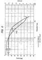
- Fig.6 is a Bode diagram showing two examples of measuring the frequency characteristic of the motor-driving circuit system in the electric power steering apparatus using the brushless motor, and a curve shown by a solid line in Fig.6 shows a gain characteristic and a phase characteristic as a measurement result in a first measurement example and shows a line-to-line frequency characteristic of the motor-driving circuit system when a line-to-line inductance L of the motor is 162 [ ⁇ H] , a line-to-line internal resistance R is 53 [m ⁇ ] and a line-to-line external resistance R' is 6 [m ⁇ ] .
- a curve shown by a dotted line in Fig.6 shows a gain characteristic and a phase characteristic as a measurement result in a second measurement example and shows a line-to-line frequency characteristic of the motor-driving circuit system when the line-to-line inductance L of the motor is 162 [ ⁇ H] , the line-to-line internal resistance R is 53 [m ⁇ ] and the line-to-line external resistance R' is 4.5[m ⁇ ].
- a constitution providing a resistance adjusting unit for resolving or reducing a difference of resistance components in a motor-driving circuit system among respective phases by providing a pertinent resistor in a current path in correspondence with a phase of the motor-driving circuit system which is not inserted with a relay in order to resolve a difference of gains and phases of the motor-driving circuit system among respective phases in an electric power steering apparatus using a brushless motor.
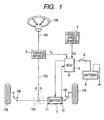
- Fig. 1 is an outline view showing a constitution of an electric power steering apparatus according to an embodiment of the invention along with a constitution of a vehicle related thereto.
- the electric power steering apparatus is provided with a steering shaft 102 one end which is fixedly attached to a handle (steering wheel) 100 constituting an operating unit for steering, a rack pinion mechanism 104 connected to other end of the steering shaft 102, a torque sensor 3 for detecting a steering torque applied to the steering shaft 102 by operating the steering wheel 100, a brushless motor 6 for generating a steering assisting force for alleviating a load of the driver in steering wheel operation (steering operation), a ball screw driving portion 11 for transmitting the steering assisting force to a rack shaft, a position sensor 12 of a resolver or the like for detecting a rotational position of a rotor of the motor 6, and an electronic control unit (ECU 5) for controlling to drive the motor 6 based on sensor signals from the torque sensor 3, a vehicle speed sensor 4 and the position sensor 12 by being applied with
- the torque sensor 3 detects the steering torque by the operation and outputs a steering torque signal Ts indicating the steering torque.
- the vehicle speed sensor 4 detects a vehicle speed which is a running speed of the vehicle and outputs a vehicle speed signal Vs indicating the vehicle speed.
- ECU 5 as a control apparatus drives the motor 6 based on the steering torque signal Ts and the vehicle speed signal Vs and the rotational position of the rotor detected by the position sensor 12. Thereby, the motor 6 generates the steering assisting force and by applying the steering assisting force to the rack shaft via the ball screw driving portion 11, the load of the driver in the steering operation is alleviated.
- the rack shaft is reciprocally moved.by a sum of the steering force by the steering torque applied by operating the steering wheel and the steering assisting force generated by the motor 6.
- Both ends of the rack shaft are connected to wheels 108 via connecting members 106 each comprising a tie rod and a knuckle arm and directions of the wheel 108 are changed in accordance with reciprocal movement of the rack shaft.
- Fig.2 is a block diagram showing a constitution of ECU 5 which is a control apparatus of the electric power steering apparatus.
- ECU 5 is provided with a motor control portion 20, a motor driving portion 30, a relay driving circuit 70 and 2 pieces of current detectors 81, 82.
- the motor control portion 20 is a control operating unit constituted by a microcomputer and is operated by executing a predetermined program stored in a memory at inside thereof.
- the motor driving portion 30 is constituted by a PWM signal generating circuit 40 and a driving circuit 50.
- Hi side FET power source line side FET
- Lo side FET ground line side FET
- a circuit portion on the power source line side including FET 51H through 53H are referred to as "upper arm”
- a circuit portion on the ground line side including FET 51L through 53 L are referred to as “lower arm”.
- Respective connection points Nu, Nv, Nw of the upper arm and the lower arm are connected to terminals 61 through 63 of respective phases of the motor by lead wires for power (specifically, constituted by bus bars), thereby, current supply paths for supplying driving currents from the driving circuit 50 to the motor 6 are formed for respective phases.
- a relay 91 is inserted into the current supply path formed by the lead wire connecting the connection point Nu in correspondence with u phase and the motor terminal 61 (hereinafter, referred to as "current supply path for u phase”)
- a relay 92 is inserted into the current supply path formed by the lead wire connecting the connection point Nv in correspondence with v phase and the motor terminal 62 (hereinafter, referred to as "current supply path for v phase”), respectively.
- a relay 90 is also inserted between a connection point (power source side branch point, mentioned later) in which source terminals of the Hi side FET 51H through 53H are connected to each other and the battery 8.
- a relay is not inserted into the current supply path (hereinafter, referred to as “current supply path for w phase”) formed by the lead wire connecting the connection point Nw in correspondence with w phase and the motor terminal 63.
- the current detector 81 on one side in 2 pieces of the current detectors 81, 82 detects u phase current flowing in the lead wire connecting the connection point Nu of the driving circuit 50 and the motor terminal 61 (current supply path for u phase), and the current detector 82 on other side detects v phase current flowing in the lead wire (current supply path for v phase) connecting the connection point Nv of the driving circuit 50 and the motor terminal 62.
- Current values detected by the current detectors 81, 82 are respectively inputted to the motor control portion 20 as a u phase current detected value Iu and a v phase current detected value Iv.
- the motor control portion 20 receives a steering torque detected by the torque sensor 3, a vehicle speed detected by the vehicle speed sensor 4, and u phase and v phase current detected values Iu, Iv detected by the current detectors 81, 82. Further, the motor control portion 20 determines a target current value to be made to flow to the motor 6 based on the steering torque and the vehicle speed in reference to a table for corresponding the steering torque and the target current value which is referred to as an assist map. Further, instruction values V*u, V*v, V*w of respective phases to be supplied to the motor 6 are calculated by proportional integrating operation based on a deviation between the target current value and a motor current value calculated by the motor current detected values Iu, Iv.
- V*u, V*v, V*w of the respective phase voltages are expressed by a rotating orthogonal coordinates system (referred to as "d-q coordinates") comprising d axis in a direction of a magnetic flux by field of the rotor of the motor, and q axis which is orthogonal to d axis and a phase of which is advanced from d axis by ⁇ /2.
- d-q coordinates a rotating orthogonal coordinates system
- the current made to flow to the motor can be dealt with as a direct current comprising a d axis component and a q axis component.
- a d axis voltage instruction value is calculated by proportional integrating operation based on a deviation between a d axis component of the target current value and the d axis component of the motor current value
- a q axis voltage instruction value is calculated by proportional integrating operation based on a deviation between a q axis component of the target current value and the q axis component of the motor current value.
- the instruction values V*u, V*v, V*w of the respective phase voltages are calculated from the d axis and the q axis voltage instruction values by coordinate conversion.
- a method based on introduction of the d-q coordinates is general, the invention is not limited thereto.
- the motor control portion 20 also outputs a relay control signal for controlling the relay driving circuit 70 based on a result of a predetermined failure detecting processing.
- the PWM signal generating circuit 40 receives the instruction values V*u, V*v, V*w of the respective phase voltages from the motor control portion 20 and generates a PWM signal a duty ratio of which is changed in accordance with the instruction values V*u, V*v, V*w.
- the driving circuit 50 is a PWM voltage type inverter constituted by using the Hi side FET 51H through 53H and the Lo side FET 51L through 53L as described above for generating respective phase voltages Vu, Vv, Vw to be applied to the motor 6 by making FET 51H through 53H and 51L through 53L ON/OFF.
- the respective voltages Vu, Vv, Vw are outputted from ECU 5 to apply to the motor 6.
- currents are made to flow to coils (not illustrated) of respective phases u, v, w of the motor 6 and the motor 6 generates a torque (motor torque) for assisting steering in accordance with the currents.
- the relay driving circuit 70 is operated based on the relay control signal outputted from the control portion 20.
- the relay driving circuit 70 maintains the relays 90, 91, 92 in a closed state and continues to supply power source to the motor driving portion 30 and the motor 6 until a signal indicating that a failure is detected from the motor control portion 20 is received from the motor control portion 20.
- the relay driving circuit 70 receives the signal indicating that the failure is detected from the motor control portion 20. Thereby, the relay driving circuit 70 brings the relays 90, 91, 92 in an open state and stops to supply the power source to the motor driving portion 30 and the motor 6.
- the electric power steering apparatus is provided with the following constitution for resolving or reducing differences of resistance components among respective phases (among respective phases u, v, w) in a motor-driving circuit system which is a constitution portion comprising the driving circuit 50, the brushless motor 6 and the lead wires connecting these and the like.
- a motor-driving circuit system which is a constitution portion comprising the driving circuit 50, the brushless motor 6 and the lead wires connecting these and the like.
- the transfer function Gm(s) of the motor-driving circuit system can be expressed by the following equation with regard to the respective phases (refer to Fig.4) .
- Gm(s) Km/ (L ⁇ s + R + R') where notation Km designates a constant, and notation R' designates the external resistance including the wiring resistance of the lead wires forming the current supply paths for the respective phases and so on.
- the relay 91 is inserted into the current supply path for u phase connecting the connection point Nu at inside of the driving circuit 50 and the motor terminal 61 and the relay 92 is inserted into the current supply path for v phase connecting the connection point Nv at inside of the driving circuit 50 and the motor terminal 62, a relay is not inserted into the current supply path for w phase connecting the connection point Nw at inside of the driving circuit 50 and the motor terminal 63.
- the current supply path for w phase is inserted with a resistor member Ra having a resistance value substantially equal to a contact resistance value which is a resistance value in an ON state of the relay 91 or 92.
- the resistor member Ra By inserting the resistor member Ra, the differences of the resistance components of the external resistor R' with regard to electric connection between the driving circuit 50 and the motor 6, that is, the differences of resistance values of the current supply paths for supplying the currents from the driving circuit 50 to the motor 6 are reduced or resolved. Further, although in inserting the resistor member Ra, specifically, a resistor in correspondence therewith may be inserted into the current supply path for w phase into which a relay is not inserted, in place thereof, insertion of the resistor member Ra may be realized by pertinently setting a sectional area (width or thickness) and/or a length of the bus bar forming the lead wire as the current supply path for w phase as described later.
- a wiring resistance at inside of the driving circuit 50 is adjusted. That is, when the 3 phase voltage type inverter shown by Fig. 3A is used as the driving circuit 50, it is difficult to make wiring lengths between the power source and FET 51H through 53H which are the switching elements on the Hi side and wiring lengths between the ground point and FET 51L through 53L which are the switching elements on the Lo side.
- a bus bar 55H at and after a connection point (hereinafter, referred to as "power source side branch point") NH branching respectively to the Hi side FET 51H through 53H is provided with a shape as shown by Fig.3B.
- a bus bar 55L at and after a connection point (hereinafter, referred to as "ground side branch point") NL branching to the respective Lo side FET 51L through 53L in the current paths reaching the Lo side FET 51L through 53L from the ground point is provided with a shape as shown by Fig.3C.
- the wiring resistances are adjusted among the respective phases by pertinently setting the width W1 through W3 and W4 through W6 of the bus bars 55H, 55L.
- the differences among the respective phases of the resistance components in the driving circuit 50 may be reduced or resolved by adjusting the wiring resistances among the respective phases by adjusting the thicknesses (or sectional areas) and/or the lengths along with the widths or in place of the widths.
- the differences among the respective phases are resolved or reduced with regard to the resistance values of the current supply paths for supplying the currents from the driving circuit 50 to the motor 6 and the resistance values of the wirings at inside of the driving circuit 50, thereby, the differences among the respective phases of the external resistance R' in the motor-driving circuit system are resolved or reduced.
- the differences of the internal resistance R and the inductance L are substantially to a negligible degree and therefore, not only the differences among the respective phases of the resistance components in the motor-driving circuit system are resolved or reduced as described above but also the gains and the phases of the motor-driving circuit system with regard to respective phases are substantially equal to each other.
- the resistance components in the motor-driving circuit system are adjusted and therefore, it is not necessary to separately add a resistor or the like for adjusting the resistances among the phases. Therefore, the differences of the gains and the phases of the motor-driving circuit system among the phase can be reduced or resolved while restraining an increase in cost.
- the adjusting resistor member Ra is inserted into the path which is not inserted with a relay in the current supply paths for supplying the currents from the driving circuit 50 to the motor 6 (Fig.2) and there is constructed a constitution in which the shapes of the bus bars forming the wirings at inside of the driving circuit 50 are adjusted (Figs.3A to 3C) , in place thereof, there may be constructed a constitution of adopting only either one of the two resistance adjusting units for adjusting the resistance components of the motor-driving circuit system among the phases.
- the relays when the relays are inserted to all of the current supply paths reaching the motor 6 from the driving circuit 50, only the wiring resistance at inside of the driving circuit 50 may be adjusted (for example, pertinently setting the widths of the bus bars).
- the brushless motor 6 of 3 phases is used as the drive source of the electric power steering apparatus
- a number of phases of the brushless motor is not limited to 3 but the invention is applicable also to an electric power steering apparatus using a brushless motor of 4 or more phases.
Landscapes
- Engineering & Computer Science (AREA)
- Chemical & Material Sciences (AREA)
- Combustion & Propulsion (AREA)
- Transportation (AREA)
- Mechanical Engineering (AREA)
- Power Steering Mechanism (AREA)
- Control Of Motors That Do Not Use Commutators (AREA)
Applications Claiming Priority (2)
| Application Number | Priority Date | Filing Date | Title |
|---|---|---|---|
| JP2003294671A JP2005065443A (ja) | 2003-08-18 | 2003-08-18 | 電動パワーステアリング装置 |
| JP2003294671 | 2003-08-18 |
Publications (3)
| Publication Number | Publication Date |
|---|---|
| EP1508496A2 true EP1508496A2 (fr) | 2005-02-23 |
| EP1508496A3 EP1508496A3 (fr) | 2007-01-24 |
| EP1508496B1 EP1508496B1 (fr) | 2008-10-15 |
Family
ID=34056215
Family Applications (1)
| Application Number | Title | Priority Date | Filing Date |
|---|---|---|---|
| EP04019298A Expired - Fee Related EP1508496B1 (fr) | 2003-08-18 | 2004-08-13 | Direction assistée électrique |
Country Status (5)
| Country | Link |
|---|---|
| US (1) | US7009349B2 (fr) |
| EP (1) | EP1508496B1 (fr) |
| JP (1) | JP2005065443A (fr) |
| KR (1) | KR20050020623A (fr) |
| DE (1) | DE602004017096D1 (fr) |
Cited By (1)
| Publication number | Priority date | Publication date | Assignee | Title |
|---|---|---|---|---|
| FR2892085A1 (fr) * | 2005-10-19 | 2007-04-20 | Koyo Steering Europ Soc Par Ac | Procede pour determiner en temps reel la tenue d'un volant de conduite d'une direction assistee electrique de vehicule automobile |
Families Citing this family (12)
| Publication number | Priority date | Publication date | Assignee | Title |
|---|---|---|---|---|
| JP4039317B2 (ja) * | 2003-06-12 | 2008-01-30 | 株式会社ジェイテクト | 電動パワーステアリング装置 |
| JP4644013B2 (ja) * | 2005-03-25 | 2011-03-02 | 本田技研工業株式会社 | 電動パワーステアリング装置 |
| SG130957A1 (en) * | 2005-09-15 | 2007-04-26 | St Microelectronics Asia | An electrical isolation circuit for preventing current flow from an electrical application to a dc power source |
| JP4449918B2 (ja) * | 2006-02-15 | 2010-04-14 | トヨタ自動車株式会社 | 電動パワーステアリング装置 |
| JP4767315B2 (ja) * | 2006-04-13 | 2011-09-07 | 三菱電機株式会社 | 電動パワーステアリング制御装置 |
| JP5082719B2 (ja) * | 2007-09-26 | 2012-11-28 | 株式会社ジェイテクト | モータ制御装置及び電動パワーステアリング装置 |
| JP5428325B2 (ja) * | 2008-08-25 | 2014-02-26 | 株式会社ジェイテクト | モータ制御装置および電動パワーステアリング装置 |
| US8560178B2 (en) * | 2011-11-30 | 2013-10-15 | Steering Solutions Ip Holding Corporation | System and method for providing steering torque assistance to an electrically-powered steering apparatus of a vehicle |
| US9487231B2 (en) * | 2013-11-26 | 2016-11-08 | Steering Solutions Ip Holding Corporation | Tie rod force sensing systems and methods |
| WO2017037942A1 (fr) * | 2015-09-04 | 2017-03-09 | 三菱電機株式会社 | Dispositif d'attaque de moteur et climatiseur |
| US11124224B2 (en) * | 2019-11-27 | 2021-09-21 | Hiwin Technologies Corp. | Electric power steering system |
| US11866106B2 (en) * | 2021-03-19 | 2024-01-09 | Ford Global Technologies, Llc | Methods and apparatus to determine loads encountered by a steering rack |
Citations (4)
| Publication number | Priority date | Publication date | Assignee | Title |
|---|---|---|---|---|
| US4544868A (en) * | 1984-07-20 | 1985-10-01 | General Motors Corporation | Brushless DC motor controller |
| JP2001106098A (ja) * | 1999-10-12 | 2001-04-17 | Mitsubishi Electric Corp | 電動式パワーステアリング装置 |
| WO2002009999A2 (fr) * | 2000-07-27 | 2002-02-07 | Motorola, Inc. | Procede et systeme permettant de tester la continuite d'un moteur et des circuits d'entrainement associes |
| US6400116B1 (en) * | 1998-06-09 | 2002-06-04 | Nsk Ltd. | Motor drive control apparatus |
Family Cites Families (3)
| Publication number | Priority date | Publication date | Assignee | Title |
|---|---|---|---|---|
| JP2959957B2 (ja) * | 1994-06-06 | 1999-10-06 | 本田技研工業株式会社 | 電動パワーステアリング |
| CA2338230A1 (fr) * | 1998-07-21 | 2000-02-03 | Edward H. Phillips | Retroaction et commande asservie pour systemes electriques de direction assistee |
| JP4033030B2 (ja) * | 2003-04-21 | 2008-01-16 | 株式会社ジェイテクト | 電動パワーステアリング装置 |
-
2003
- 2003-08-18 JP JP2003294671A patent/JP2005065443A/ja active Pending
-
2004
- 2004-08-12 KR KR1020040063409A patent/KR20050020623A/ko not_active Application Discontinuation
- 2004-08-13 EP EP04019298A patent/EP1508496B1/fr not_active Expired - Fee Related
- 2004-08-13 DE DE602004017096T patent/DE602004017096D1/de active Active
- 2004-08-17 US US10/919,268 patent/US7009349B2/en not_active Expired - Fee Related
Patent Citations (4)
| Publication number | Priority date | Publication date | Assignee | Title |
|---|---|---|---|---|
| US4544868A (en) * | 1984-07-20 | 1985-10-01 | General Motors Corporation | Brushless DC motor controller |
| US6400116B1 (en) * | 1998-06-09 | 2002-06-04 | Nsk Ltd. | Motor drive control apparatus |
| JP2001106098A (ja) * | 1999-10-12 | 2001-04-17 | Mitsubishi Electric Corp | 電動式パワーステアリング装置 |
| WO2002009999A2 (fr) * | 2000-07-27 | 2002-02-07 | Motorola, Inc. | Procede et systeme permettant de tester la continuite d'un moteur et des circuits d'entrainement associes |
Cited By (3)
| Publication number | Priority date | Publication date | Assignee | Title |
|---|---|---|---|---|
| FR2892085A1 (fr) * | 2005-10-19 | 2007-04-20 | Koyo Steering Europ Soc Par Ac | Procede pour determiner en temps reel la tenue d'un volant de conduite d'une direction assistee electrique de vehicule automobile |
| WO2007045735A1 (fr) * | 2005-10-19 | 2007-04-26 | Jtekt Europe | Procede pour determiner en temps reel la tenue d'un volant de conduite d'une direction assistee electrique de vehicule automobile |
| US8447470B2 (en) | 2005-10-19 | 2013-05-21 | Jtekt Europe | Method for determining, in real time, the grip on a steering wheel of an electric power-assisted steering system for automobile |
Also Published As
| Publication number | Publication date |
|---|---|
| EP1508496A3 (fr) | 2007-01-24 |
| DE602004017096D1 (de) | 2008-11-27 |
| US7009349B2 (en) | 2006-03-07 |
| KR20050020623A (ko) | 2005-03-04 |
| JP2005065443A (ja) | 2005-03-10 |
| EP1508496B1 (fr) | 2008-10-15 |
| US20050040781A1 (en) | 2005-02-24 |
Similar Documents
| Publication | Publication Date | Title |
|---|---|---|
| EP1526060B1 (fr) | Système de direction assistée | |
| EP1959556B1 (fr) | Contrôleur de moteur | |
| US7009349B2 (en) | Electric power steering apparatus | |
| EP1955928B1 (fr) | Contrôleur de moteur et système à direction assistée électrique | |
| US8217600B2 (en) | Motor control device and electric power steering system | |
| EP2573523B1 (fr) | Dispositif de détection de déplacement, système de direction de véhicule et moteur | |
| US7427843B2 (en) | Electrically operated power steering controller and adjusting method of driving electric current offset in this controller | |
| EP3082253A1 (fr) | Dispositif de commande de moteur et système de direction assistée électrique | |
| US6972537B2 (en) | Electric power steering apparatus | |
| US7044264B2 (en) | Electrically driven power steering system for vehicle | |
| EP1564877B1 (fr) | Dispositif pour l'entraînement d'un moteur sans balais | |
| EP1985523A2 (fr) | Systèmes et procédés pour contrôler le couple d'un moteur | |
| JP2003324985A (ja) | モータ制御装置 | |
| US6397971B1 (en) | Electrically powered steering system | |
| EP3528381B1 (fr) | Appareil de commande de moteur | |
| JP4140454B2 (ja) | 電動パワーステアリング装置 | |
| JP2002005968A (ja) | 電流検出装置 |
Legal Events
| Date | Code | Title | Description |
|---|---|---|---|
| PUAI | Public reference made under article 153(3) epc to a published international application that has entered the european phase |
Free format text: ORIGINAL CODE: 0009012 |
|
| AK | Designated contracting states |
Kind code of ref document: A2 Designated state(s): AT BE BG CH CY CZ DE DK EE ES FI FR GB GR HU IE IT LI LU MC NL PL PT RO SE SI SK TR |
|
| AX | Request for extension of the european patent |
Extension state: AL HR LT LV MK |
|
| RAP1 | Party data changed (applicant data changed or rights of an application transferred) |
Owner name: JTEKT CORPORATION |
|
| PUAL | Search report despatched |
Free format text: ORIGINAL CODE: 0009013 |
|
| AK | Designated contracting states |
Kind code of ref document: A3 Designated state(s): AT BE BG CH CY CZ DE DK EE ES FI FR GB GR HU IE IT LI LU MC NL PL PT RO SE SI SK TR |
|
| AX | Request for extension of the european patent |
Extension state: AL HR LT LV MK |
|
| 17P | Request for examination filed |
Effective date: 20070308 |
|
| AKX | Designation fees paid |
Designated state(s): DE FR GB |
|
| GRAP | Despatch of communication of intention to grant a patent |
Free format text: ORIGINAL CODE: EPIDOSNIGR1 |
|
| GRAS | Grant fee paid |
Free format text: ORIGINAL CODE: EPIDOSNIGR3 |
|
| GRAA | (expected) grant |
Free format text: ORIGINAL CODE: 0009210 |
|
| AK | Designated contracting states |
Kind code of ref document: B1 Designated state(s): DE FR GB |
|
| REG | Reference to a national code |
Ref country code: GB Ref legal event code: FG4D |
|
| REF | Corresponds to: |
Ref document number: 602004017096 Country of ref document: DE Date of ref document: 20081127 Kind code of ref document: P |
|
| PLBE | No opposition filed within time limit |
Free format text: ORIGINAL CODE: 0009261 |
|
| STAA | Information on the status of an ep patent application or granted ep patent |
Free format text: STATUS: NO OPPOSITION FILED WITHIN TIME LIMIT |
|
| 26N | No opposition filed |
Effective date: 20090716 |
|
| GBPC | Gb: european patent ceased through non-payment of renewal fee |
Effective date: 20090813 |
|
| PG25 | Lapsed in a contracting state [announced via postgrant information from national office to epo] |
Ref country code: GB Free format text: LAPSE BECAUSE OF NON-PAYMENT OF DUE FEES Effective date: 20090813 |
|
| PGFP | Annual fee paid to national office [announced via postgrant information from national office to epo] |
Ref country code: DE Payment date: 20100812 Year of fee payment: 7 Ref country code: FR Payment date: 20100824 Year of fee payment: 7 |
|
| REG | Reference to a national code |
Ref country code: FR Ref legal event code: ST Effective date: 20120430 |
|
| REG | Reference to a national code |
Ref country code: DE Ref legal event code: R119 Ref document number: 602004017096 Country of ref document: DE Effective date: 20120301 |
|
| PG25 | Lapsed in a contracting state [announced via postgrant information from national office to epo] |
Ref country code: FR Free format text: LAPSE BECAUSE OF NON-PAYMENT OF DUE FEES Effective date: 20110831 |
|
| PG25 | Lapsed in a contracting state [announced via postgrant information from national office to epo] |
Ref country code: DE Free format text: LAPSE BECAUSE OF NON-PAYMENT OF DUE FEES Effective date: 20120301 |