EP1508404A2 - Dispositif de support pour pièce à usiner - Google Patents
Dispositif de support pour pièce à usiner Download PDFInfo
- Publication number
- EP1508404A2 EP1508404A2 EP04254614A EP04254614A EP1508404A2 EP 1508404 A2 EP1508404 A2 EP 1508404A2 EP 04254614 A EP04254614 A EP 04254614A EP 04254614 A EP04254614 A EP 04254614A EP 1508404 A2 EP1508404 A2 EP 1508404A2
- Authority
- EP
- European Patent Office
- Prior art keywords
- work piece
- holding arrangement
- piece holding
- clamping
- arrangement according
- Prior art date
- Legal status (The legal status is an assumption and is not a legal conclusion. Google has not performed a legal analysis and makes no representation as to the accuracy of the status listed.)
- Granted
Links
Images


Classifications
-
- B—PERFORMING OPERATIONS; TRANSPORTING
- B25—HAND TOOLS; PORTABLE POWER-DRIVEN TOOLS; MANIPULATORS
- B25B—TOOLS OR BENCH DEVICES NOT OTHERWISE PROVIDED FOR, FOR FASTENING, CONNECTING, DISENGAGING OR HOLDING
- B25B11/00—Work holders not covered by any preceding group in the subclass, e.g. magnetic work holders, vacuum work holders
- B25B11/005—Vacuum work holders
- B25B11/007—Vacuum work holders portable, e.g. handheld
-
- B—PERFORMING OPERATIONS; TRANSPORTING
- B23—MACHINE TOOLS; METAL-WORKING NOT OTHERWISE PROVIDED FOR
- B23Q—DETAILS, COMPONENTS, OR ACCESSORIES FOR MACHINE TOOLS, e.g. ARRANGEMENTS FOR COPYING OR CONTROLLING; MACHINE TOOLS IN GENERAL CHARACTERISED BY THE CONSTRUCTION OF PARTICULAR DETAILS OR COMPONENTS; COMBINATIONS OR ASSOCIATIONS OF METAL-WORKING MACHINES, NOT DIRECTED TO A PARTICULAR RESULT
- B23Q1/00—Members which are comprised in the general build-up of a form of machine, particularly relatively large fixed members
- B23Q1/03—Stationary work or tool supports
- B23Q1/035—Stationary work or tool supports with an array of longitudinally movable rods defining a reconfigurable support surface
-
- B—PERFORMING OPERATIONS; TRANSPORTING
- B25—HAND TOOLS; PORTABLE POWER-DRIVEN TOOLS; MANIPULATORS
- B25B—TOOLS OR BENCH DEVICES NOT OTHERWISE PROVIDED FOR, FOR FASTENING, CONNECTING, DISENGAGING OR HOLDING
- B25B1/00—Vices
- B25B1/24—Details, e.g. jaws of special shape, slideways
- B25B1/2405—Construction of the jaws
- B25B1/241—Construction of the jaws characterised by surface features or material
- B25B1/2415—Construction of the jaws characterised by surface features or material being composed of a plurality of parts adapting to the shape of the workpiece
- B25B1/2421—Construction of the jaws characterised by surface features or material being composed of a plurality of parts adapting to the shape of the workpiece the parts having a linear movement
-
- B—PERFORMING OPERATIONS; TRANSPORTING
- B25—HAND TOOLS; PORTABLE POWER-DRIVEN TOOLS; MANIPULATORS
- B25B—TOOLS OR BENCH DEVICES NOT OTHERWISE PROVIDED FOR, FOR FASTENING, CONNECTING, DISENGAGING OR HOLDING
- B25B11/00—Work holders not covered by any preceding group in the subclass, e.g. magnetic work holders, vacuum work holders
- B25B11/005—Vacuum work holders
-
- B—PERFORMING OPERATIONS; TRANSPORTING
- B25—HAND TOOLS; PORTABLE POWER-DRIVEN TOOLS; MANIPULATORS
- B25B—TOOLS OR BENCH DEVICES NOT OTHERWISE PROVIDED FOR, FOR FASTENING, CONNECTING, DISENGAGING OR HOLDING
- B25B5/00—Clamps
- B25B5/14—Clamps for work of special profile
- B25B5/142—Clamps for work of special profile for windows and frames
Definitions
- This invention relates to work piece holding arrangements. More particularly, but not exclusively, the invention relates to work piece holding arrangements for holding blades of a rotary component of a gas turbine engine.
- a work piece holding arrangement comprising an array of movable engaging members for engaging a work piece, an actuator for moving a plurality of the engagement elements into engagement with the work piece, and a deformable clamping member to clamp the engagement elements, wherein the clamping member is deformable between a clamping condition in which at least some of the engagement elements are engaged by the securing member and clamped in respective positions, and a non-clamping condition in which the engagement elements can move.
- the work piece holding arrangement includes a support for supporting the engagement element in an outwardly extending array in which each engagement element is generally parallel with each other engaging elements.
- Each engagement element may comprise an elongate member movable in its longitudinal direction.
- Each engaging element may comprise an inner part and an outer part.
- the outer part may be telescopically movable over the inner part.
- the inner and outer parts may define a fluid path and each engagement element is movable by the flow of a fluid through the fluid path.
- an engagement element for use in a work piece holding arrangement comprising an inner part and an outer part, the inner and outer parts being telescopically movable relative to each other, wherein the inner and outer parts define a fluid path and the relative telescopic movement of the inner and outer parts is effected by a flow of a fluid through the fluid path.
- each engagement element may comprise cooperable respective stop formations to inhibit the telescopic movement.
- the actuator may comprise a fluid supply assembly for supplying said fluid to each engagement element.
- the inner part and the outer part may each have a respective proximal end region and a respective distal end region.
- the proximal end regions of the inner and outer parts may be nearer to the support than the respective distal end regions.
- the fluid path may extend from an inlet at the proximal end region of the inner part to an outlet at the proximal end region of the outer part.
- the fluid path may be substantially devoid of seals, and may instead have a narrow gap in the fluid path to generate a non-positive driving force on each engaging element. This has the advantage in the preferred embodiment of providing a non-positive driving force on each engagement element.
- Each engagement element may comprise an inner tubular member defining a first region of the fluid path from the inlet.
- Each engagement element may include an outer pin member defining a second region of the fluid path to the outlet.
- the cooperable stop formations may comprise an outwardly extending formation on the inner tubular member, and an inwardly extending formation on the outer pin member.
- the arrangement may include a flexible sealing member for sealingly engaging the work piece, and may further include a vacuum application means to apply a vacuum between the engagement elements.
- the outwardly extending stop formation may be provided on the distal end region of the inner tubular member.
- the inwardly extending stop formation may be provided on the proximal end of the outer pin member.
- the clamping member may comprise a clamping sleeve extending around the engagement element.
- the clamping sleeve may be deformable inwardly to engage a plurality of the engagement element.
- the securing member may comprise a shaft member arranged centrally of the engagement element.
- the shaft member may be deformable outwardly to engage a plurality of the holding members in the securing condition.
- a first embodiment of a work piece holding arrangement 10 which comprises a plurality of elongate telescopic engagement elements 12 and a support 14 for supporting the engagement elements 12.
- the engagement elements 12 provide a self-aligning hexagonal array of movable pins within the support 14.
- the support 14 comprises a base member 20 defining a fluid flow conduit 22 to supply fluid to the tubular members 18, as will be explained below.
- a cylindrical wall 24 extends upwardly from the base member 20 and surrounds the array of engagement elements 12.
- the cylindrical wall 24 comprises a deformable clamping member in the form of an inwardly deformable flexible annular bushing 26, arranged in an annular indented region 27 of the wall 24.
- An annular space 28 is defined between the bushing 26 and the wall 24. Seals 29 are arranged in the space 28 to prevent leakage of hydraulic fluid.
- the work piece holding arrangement also includes a plurality of fill members 32 of varying sizes to fill at least some of the gaps between the hexagonal array of engagement elements 12 and the bushing 26.
- a supply of hydraulic fluid to the annular space 28 causes the bushing 26 to deform inwardly thereby engaging the outermost engagement elements 12 and the fill members 32, and clamping the engagement elements 12 in their position.
- the work piece holding arrangement 10 also includes a pneumatic actuator represented diagrammatically at 34 for delivering air under pressure to the fluid flow conduit 22 in the base member 20.
- the actuator could be a hydraulic actuator.
- One of the engagement elements 12 is shown in Fig. 8 and comprises an outer hollow elongate pin member 16, and an inner tubular shaft 18.
- the outer pin member 16 defines a central longitudinally extending outer conduit 17, the purpose of which is explained below.
- the outer pin member 16 is telescopically slidable over the inner tubular member 18 as shown by the double headed arrow A in Fig. 8.
- the inner tubular member 18 defines a central longitudinally extending inner conduit 19 in communication with the outer conduit 17. The purpose of the inner conduit 19 is also explained below.
- Each outer pin 16 can slide along its main longitudinal axis but is constrained in all other axes. Engagement elements around the perimeter are so constrained partially by neighbouring engagement elements 12 and partially by fill members 32.
- Each inner tubular member 18 has a proximal end region 40 at which the tubular member is mounted on the base member 20, and an opposite distal end region 42 spaced from the base member 20.
- the outer pin member 16 has a proximal end region 44 nearest to the base member 20 and a distal end region 46 spaced from the proximal end region 44 of the outer pin member 16.
- the distal end region 46 of the outer pin member 16 is for engagement with a work piece, as will be described below.
- a fluid flow path 48 (see Fig. 9) is defined within each engaging element 12 and is provided by the outer and inner conduits 17, 19.
- the fluid flow path 48 extends from the proximal end region 40 of the inner tubular member 18 to the distal end region 42 of the inner tubular member 18 and thereafter from the inner conduit 19 in the tubular member 18.
- the fluid (which, in the preferred embodiment, is air) enters the inner conduit 19 within the inner tubular member 18 as shown by the arrow 50A and flows into the outer conduit 17 in the outer pin member 16, as shown by the arrows 50C to exit therefrom at the proximal end region 44 of the outer pin member 16, as shown by the arrows 50B.
- stop formations 52, 54 are provided in order to prevent the outer pin members 16 sliding off their respective inner tubular members 18.
- the stop formation 54 is provided on the proximal end region 44 of the outer pin member 16 and extends radially inwardly towards the tubular member 18.
- the stop formation 52 is provided on the distal end region 42 of the inner tubular member 18 and extends radially outwardly.
- a bottleneck 49 is provided in the fluid flow path 48 between the stop formation 52 on the inner tubular member 18 and the portion of the outer pin member 16 providing the wall of the outer conduit 17 and thereby the air flows freely all along.
- the pressure of the fluid is sufficient to move each outer pin member 16 upwards until the distal end region 46 engages a part of the work piece, or until the stop formations 52, 54 engage each other.
- the fluid is allowed to escape, as shown by the arrows 50 and gently pushes the outer pin member away from the base member 20 to provide a feather touch on the work piece, thereby avoiding deformation of the work piece.
- a supply of air from the pneumatic actuator 34 causes each of the pin members 16 of the engagement elements 12 to slide telescopically outwardly along the respective inner tubular members 18 until distal end region 46 of some of the pin members engage a work piece.
- hydraulic fluid is supplied to the space 28 between the bushing 26 and the wall 24 to cause the bushing 26 to deform inwardly thereby clamping the outer pin members 16 in position.
- the outer pin members 16 engage the work piece holding it in position for suitable clamping.
- the work piece could be held in position by opposed work piece holding arrangements 10 arranged for the respective pin members 16 of each work piece holding arrangement 10 to engage the work piece on opposite sides thereof.
- a flexible sealing member in the form of an annular bellowed vacuum cup 60 is provided in order to hold the work piece to the engaging elements 12.
- a bore 62 is defined in the wall 24 via which air can be removed from the spaces 64 between adjacent engaging members 12. The vacuum cup 60 seals against the work piece and a vacuum is applied to hold the work piece in position.
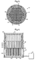
- the clamping member may comprise an inner shaft 124 member having a radially outwardly deformable sleeve 126 to clamp the pins from the centre outwards, as shown in Fig. 5.
- An annular space 128 is defined between the shaft 124 and the sleeve 126 is provided to receive hydraulic fluid therein to deform the outwardly deformable sleeve 126.
- a plurality of central elongate fill members 132 are provided adjacent the sleeve 126 to transmit the outward clamping force to the engagement members 12.
- FIG. 6 and 7 Another embodiment is shown in Figs. 6 and 7 which is similar to the embodiment shown in Figs. 1 to 4 and the same features have been designated with the same respective number. However, the embodiment shown in Figs. 6 and 7 differ in that the support 14 is of a rectangular configuration, having four generally planar wall sections 124.
- the engagement elements 12 are arranged in a self-aligning pattern, which is of a rectangular configuration to correspond to the shape of the support 14.
- the embodiment shown in Figs. 6 and 7 also differs from the embodiment shown in Figs. 1 to 4 in that a clamping strip 126 is used instead of the clamping bushing 26.
- the clamping strip 126 is provided across only one of the wall sections 114, but could be in at least one, or all, of the other wall sections 114 if higher clamping loads are required.
- the clamping strip 126 is deformable inwardly, as shown by the arrow B by the introduction of hydraulic fluid via a hydraulic fluid conduit 128 into the rectangular space 28.
- a work piece holding arrangement 10 for holding a work piece such as a blade of a rotary component of a gas turbine engine, or a vane of a stationary component.
- the preferred embodiment includes an array of pneumatically or hydraulically actuated engaging elements 12 which are movable outwardly to engage the work piece.
- Each engaging element defines a pathway 48 for the flow of fluid therethrough, the pathway 48 having an outlet to atmosphere which allows the free flow of fluid through the pathway 48.
- This has the advantage in the preferred embodiment of gently moving the outer pin members 16 outwardly to lightly engage the work piece. Upon such engagement no, or very little, further force is applied to the work piece by the pin member 16.
- hydraulic fluid is supplied to the space 28, 128 to deform inwardly the bushing 26 or the strip 126 to clamp the pin members 16 in position.
Applications Claiming Priority (2)
| Application Number | Priority Date | Filing Date | Title |
|---|---|---|---|
| GB0319727 | 2003-08-22 | ||
| GBGB0319727.4A GB0319727D0 (en) | 2003-08-22 | 2003-08-22 | Work piece holding arrangement |
Publications (3)
| Publication Number | Publication Date |
|---|---|
| EP1508404A2 true EP1508404A2 (fr) | 2005-02-23 |
| EP1508404A3 EP1508404A3 (fr) | 2009-05-13 |
| EP1508404B1 EP1508404B1 (fr) | 2011-01-26 |
Family
ID=28460108
Family Applications (1)
| Application Number | Title | Priority Date | Filing Date |
|---|---|---|---|
| EP04254614A Expired - Fee Related EP1508404B1 (fr) | 2003-08-22 | 2004-07-30 | Dispositif de support pour pièce à usiner |
Country Status (4)
| Country | Link |
|---|---|
| US (1) | US7125010B2 (fr) |
| EP (1) | EP1508404B1 (fr) |
| DE (1) | DE602004031181D1 (fr) |
| GB (1) | GB0319727D0 (fr) |
Cited By (7)
| Publication number | Priority date | Publication date | Assignee | Title |
|---|---|---|---|---|
| WO2005061147A2 (fr) * | 2003-12-24 | 2005-07-07 | Surface Generation Ltd | Systeme d'outillage ameliore |
| DE102005017697A1 (de) * | 2005-04-07 | 2006-10-12 | L.M.F. Fahrzeugtechnik Gmbh | Messvorrichtung und Kalibrierverfahren zu deren Kalibrierung |
| WO2007045343A1 (fr) * | 2005-10-20 | 2007-04-26 | Deutsche Solar Ag | Dispositif et procede pour fixer des blocs en metal non ferreux |
| EP2082836A1 (fr) * | 2008-01-24 | 2009-07-29 | Hubert Meintrup | Dispositif de positionnement pour pièces à usiner |
| CN103878710A (zh) * | 2012-12-21 | 2014-06-25 | J.施迈茨有限公司 | 夹紧装置 |
| WO2019012118A1 (fr) * | 2017-07-14 | 2019-01-17 | Homag Gmbh | Dispositif d'ablocage avec fonction d'enlèvement |
| EP3578323A1 (fr) * | 2018-06-05 | 2019-12-11 | C.R.F. Società Consortile per Azioni | Dispositif de préhension de type aspirant |
Families Citing this family (24)
| Publication number | Priority date | Publication date | Assignee | Title |
|---|---|---|---|---|
| GB0319727D0 (en) * | 2003-08-22 | 2003-09-24 | Rolls Royce Plc | Work piece holding arrangement |
| GB0403693D0 (en) * | 2004-02-19 | 2004-03-24 | Douglas Equipment Ltd | An aircraft handler |
| US7735815B2 (en) * | 2004-03-27 | 2010-06-15 | Airbus Deutschland Gmbh | Holding device for generating a retaining pressure on an airplane component |
| GB0428339D0 (en) * | 2004-12-24 | 2005-02-02 | Surface Generation Ltd | Improved tooling system |
| US20060244190A1 (en) * | 2005-04-29 | 2006-11-02 | Gunter Erdmann | Pin locking method and apparatus for pin-supported workpieces |
| GB0518743D0 (en) * | 2005-09-14 | 2005-10-19 | Surface Generation Ltd | Improved tooling system |
| US7819876B2 (en) * | 2005-10-25 | 2010-10-26 | Zimmer Technology, Inc. | Orthopaedic pin driver |
| CN100500368C (zh) * | 2006-02-24 | 2009-06-17 | 鸿富锦精密工业(深圳)有限公司 | 一种治具 |
| KR100722259B1 (ko) | 2006-08-23 | 2007-05-29 | 엠케이프리시젼 주식회사 | 원형봉을 관입시키기 위한 지그 |
| US7726637B2 (en) * | 2007-09-10 | 2010-06-01 | Gm Global Technology Operations, Inc. | Reconfigurable clamp and method of use thereof |
| US8267390B2 (en) * | 2008-06-11 | 2012-09-18 | GM Global Technology Operations LLC | Locking mechanism and reconfigurable clamp incorporating the same |
| US8504205B2 (en) | 2011-03-17 | 2013-08-06 | Harris Corporation | Robotic grasping device with multi-force sensing at base of fingers |
| US8534729B2 (en) | 2011-08-04 | 2013-09-17 | Harris Corporation | High-force robotic gripper |
| US8534728B1 (en) * | 2012-11-19 | 2013-09-17 | Harris Corporation | Adaptive robotic gripper |
| DE102015101599B3 (de) * | 2015-02-04 | 2016-05-19 | Matrix Gmbh Spannsysteme Und Produktionsautomatisierung | Greifkopf |
| US10046399B2 (en) * | 2015-10-19 | 2018-08-14 | James J. Youngers | Lathe tool mounting expander |
| DE102017118650A1 (de) | 2017-08-16 | 2019-02-21 | Volkswagen Aktiengesellschaft | Hydraulisches Konturstück und Spannvorrichtung mit mindestens einem hydraulischen Konturstück |
| DE102017119193A1 (de) | 2017-08-22 | 2019-02-28 | Fraunhofer-Gesellschaft zur Förderung der angewandten Forschung e.V. | Klemmbares Konturstück und Spannvorrichtung mit mindestens einem klemmbaren Konturstück |
| KR102459994B1 (ko) * | 2018-05-21 | 2022-10-28 | 한국전자통신연구원 | 재구성 가능한 지그 장치 |
| CN109719666B (zh) * | 2018-12-28 | 2021-05-28 | 深圳凯鸿欣电子科技有限公司 | 多尺寸电动螺丝刀 |
| JP7191324B2 (ja) * | 2019-03-12 | 2022-12-19 | 株式会社片山製作所 | 冷却体の加工治具 |
| US20210260720A1 (en) * | 2020-02-21 | 2021-08-26 | Wichita State University | Systems and methods for automated sanding |
| WO2022115560A1 (fr) * | 2020-11-25 | 2022-06-02 | Tpi Composites, Inc. | Élément de support universel pour pale d'éolienne |
| CN115338665A (zh) * | 2022-10-19 | 2022-11-15 | 潍坊市凯隆机械有限公司 | 一种工件加工用夹具 |
Citations (3)
| Publication number | Priority date | Publication date | Assignee | Title |
|---|---|---|---|---|
| FR2325466A1 (fr) * | 1975-09-25 | 1977-04-22 | Westin & Backlund Ab | Dispositif de maintien et de serrage de pieces de forme irreguliere |
| US5407185A (en) * | 1993-08-26 | 1995-04-18 | Hughes Aircraft Company | Reconfigurable clamp |
| DE19910519A1 (de) * | 1999-03-10 | 2000-09-14 | Stuertz Maschbau | Verfahren und Vorrichtung zum Festspannen von Profilstäben |
Family Cites Families (11)
| Publication number | Priority date | Publication date | Assignee | Title |
|---|---|---|---|---|
| US1453176A (en) * | 1921-03-18 | 1923-04-24 | Perrine Lester | Compensating jaw for chucks and the like |
| US3698267A (en) * | 1970-12-18 | 1972-10-17 | Jon R Denney | Fastener actuator |
| US3983632A (en) | 1976-01-26 | 1976-10-05 | Halstead Thomas L | Contour transfer device |
| GB1584445A (en) | 1977-06-30 | 1981-02-11 | British Cast Iron Res Ass | Work holders |
| US4200272A (en) * | 1978-06-12 | 1980-04-29 | Bcira | Holder for irregularly shaped articles |
| IT1204968B (it) | 1987-04-14 | 1989-03-10 | Gian Piero Barozzi | Attrezzatura per il supporto di pezzi di forma qualsiasi in linee di lavorazione automatizzate |
| IT1210376B (it) | 1987-06-04 | 1989-09-14 | Jobs Spa | Apparecchiatura e metodo per il fissaggio di lastre curve da sottoporre a lavorazione |
| US5190273A (en) * | 1987-12-10 | 1993-03-02 | Sz S.R.L. | Pallet with adjustable anchorage system for equipping the clamping fixture of a rough piece to be machined with machine tools |
| US5622090A (en) * | 1995-10-17 | 1997-04-22 | Worktools, Inc. | Scalloped interior socket tool |
| US5984293A (en) * | 1997-06-25 | 1999-11-16 | Mcms, Inc. | Apparatus for holding printed circuit board assemblies in manufacturing processes |
| GB0319727D0 (en) * | 2003-08-22 | 2003-09-24 | Rolls Royce Plc | Work piece holding arrangement |
-
2003
- 2003-08-22 GB GBGB0319727.4A patent/GB0319727D0/en not_active Ceased
-
2004
- 2004-07-30 EP EP04254614A patent/EP1508404B1/fr not_active Expired - Fee Related
- 2004-07-30 DE DE602004031181T patent/DE602004031181D1/de active Active
- 2004-08-13 US US10/917,408 patent/US7125010B2/en not_active Expired - Fee Related
Patent Citations (3)
| Publication number | Priority date | Publication date | Assignee | Title |
|---|---|---|---|---|
| FR2325466A1 (fr) * | 1975-09-25 | 1977-04-22 | Westin & Backlund Ab | Dispositif de maintien et de serrage de pieces de forme irreguliere |
| US5407185A (en) * | 1993-08-26 | 1995-04-18 | Hughes Aircraft Company | Reconfigurable clamp |
| DE19910519A1 (de) * | 1999-03-10 | 2000-09-14 | Stuertz Maschbau | Verfahren und Vorrichtung zum Festspannen von Profilstäben |
Cited By (12)
| Publication number | Priority date | Publication date | Assignee | Title |
|---|---|---|---|---|
| WO2005061147A2 (fr) * | 2003-12-24 | 2005-07-07 | Surface Generation Ltd | Systeme d'outillage ameliore |
| WO2005061147A3 (fr) * | 2003-12-24 | 2005-08-18 | Surface Generation Ltd | Systeme d'outillage ameliore |
| US7610790B2 (en) | 2003-12-24 | 2009-11-03 | Surface Generation Ltd. | Tooling system |
| DE102005017697A1 (de) * | 2005-04-07 | 2006-10-12 | L.M.F. Fahrzeugtechnik Gmbh | Messvorrichtung und Kalibrierverfahren zu deren Kalibrierung |
| DE102005017697B4 (de) * | 2005-04-07 | 2007-06-06 | L.M.F. Fahrzeugtechnik Gmbh | Messvorrichtung und Kalibrierverfahren zu deren Kalibrierung |
| WO2007045343A1 (fr) * | 2005-10-20 | 2007-04-26 | Deutsche Solar Ag | Dispositif et procede pour fixer des blocs en metal non ferreux |
| EP2082836A1 (fr) * | 2008-01-24 | 2009-07-29 | Hubert Meintrup | Dispositif de positionnement pour pièces à usiner |
| CN103878710A (zh) * | 2012-12-21 | 2014-06-25 | J.施迈茨有限公司 | 夹紧装置 |
| WO2019012118A1 (fr) * | 2017-07-14 | 2019-01-17 | Homag Gmbh | Dispositif d'ablocage avec fonction d'enlèvement |
| EP3578323A1 (fr) * | 2018-06-05 | 2019-12-11 | C.R.F. Società Consortile per Azioni | Dispositif de préhension de type aspirant |
| CN110561475A (zh) * | 2018-06-05 | 2019-12-13 | C.R.F.阿西安尼顾问公司 | 抽吸式夹持装置 |
| US11167428B2 (en) | 2018-06-05 | 2021-11-09 | C.R.F. Societa Consortile Per Azioni | Suction-type gripping device |
Also Published As
| Publication number | Publication date |
|---|---|
| US20050082731A1 (en) | 2005-04-21 |
| EP1508404A3 (fr) | 2009-05-13 |
| DE602004031181D1 (de) | 2011-03-10 |
| US7125010B2 (en) | 2006-10-24 |
| GB0319727D0 (en) | 2003-09-24 |
| EP1508404B1 (fr) | 2011-01-26 |
Similar Documents
| Publication | Publication Date | Title |
|---|---|---|
| US7125010B2 (en) | Work piece holding arrangement | |
| US8671533B2 (en) | Gripper device for mounting rubber elastic rings and finger for a gripper device of this type | |
| US6095509A (en) | Clamping apparatus | |
| US8006968B2 (en) | Reconfigurable workpiece support fixture | |
| EP2199648A1 (fr) | Ensembles et procédés de joint avec plaques adaptatives | |
| TWI597446B (zh) | 具有受壓力控制的密封致動器的旋轉管套節 | |
| JP7034665B2 (ja) | タービンブレード基部でのタービンブレードの取付けまたは取外し | |
| GB2306005A (en) | Reconfigurable supporting fixture, particularly for a measuring machine | |
| EP3225779A1 (fr) | Outil d'extraction | |
| EP3498380A1 (fr) | Buse, module de buse et machine outils en étant équipées | |
| JP2018119541A (ja) | 燃焼ライナ工具 | |
| CA2458920A1 (fr) | Dispositif coulissant pour pare-poussiere | |
| US6497419B2 (en) | Expanding pullback clamping module | |
| US6739949B2 (en) | Adjustable tool body with fluid actuation | |
| US11897069B2 (en) | Device for stabilizing a workpiece in a machine tool | |
| CN105370647B (zh) | 手动换向阀 | |
| KR920004670B1 (ko) | 파지장치 | |
| JP2002036162A (ja) | 把持装置 | |
| JP5885822B2 (ja) | クランプ装置 | |
| US5957466A (en) | Machine chuck | |
| KR102555361B1 (ko) | 말단이 확장된 분배관 및 그 제조방법 | |
| CN213970123U (zh) | 一种四轴转动加工中心自动工装 | |
| CA2345844C (fr) | Appareil de regulation | |
| CN112643374A (zh) | 一种四轴转动加工中心自动工装 | |
| DE60111838D1 (de) | Mit luft angetriebene tragevorrichtung für ein bewegliches arbeitsorgan |
Legal Events
| Date | Code | Title | Description |
|---|---|---|---|
| PUAI | Public reference made under article 153(3) epc to a published international application that has entered the european phase |
Free format text: ORIGINAL CODE: 0009012 |
|
| AK | Designated contracting states |
Kind code of ref document: A2 Designated state(s): AT BE BG CH CY CZ DE DK EE ES FI FR GB GR HU IE IT LI LU MC NL PL PT RO SE SI SK TR |
|
| AX | Request for extension of the european patent |
Extension state: AL HR LT LV MK |
|
| PUAL | Search report despatched |
Free format text: ORIGINAL CODE: 0009013 |
|
| AK | Designated contracting states |
Kind code of ref document: A3 Designated state(s): AT BE BG CH CY CZ DE DK EE ES FI FR GB GR HU IE IT LI LU MC NL PL PT RO SE SI SK TR |
|
| AX | Request for extension of the european patent |
Extension state: AL HR LT LV MK |
|
| 17P | Request for examination filed |
Effective date: 20090430 |
|
| AKX | Designation fees paid |
Designated state(s): DE FR GB |
|
| GRAP | Despatch of communication of intention to grant a patent |
Free format text: ORIGINAL CODE: EPIDOSNIGR1 |
|
| GRAS | Grant fee paid |
Free format text: ORIGINAL CODE: EPIDOSNIGR3 |
|
| GRAA | (expected) grant |
Free format text: ORIGINAL CODE: 0009210 |
|
| AK | Designated contracting states |
Kind code of ref document: B1 Designated state(s): DE FR GB |
|
| REG | Reference to a national code |
Ref country code: GB Ref legal event code: FG4D |
|
| REF | Corresponds to: |
Ref document number: 602004031181 Country of ref document: DE Date of ref document: 20110310 Kind code of ref document: P |
|
| REG | Reference to a national code |
Ref country code: DE Ref legal event code: R096 Ref document number: 602004031181 Country of ref document: DE Effective date: 20110310 |
|
| PLBE | No opposition filed within time limit |
Free format text: ORIGINAL CODE: 0009261 |
|
| STAA | Information on the status of an ep patent application or granted ep patent |
Free format text: STATUS: NO OPPOSITION FILED WITHIN TIME LIMIT |
|
| 26N | No opposition filed |
Effective date: 20111027 |
|
| REG | Reference to a national code |
Ref country code: DE Ref legal event code: R097 Ref document number: 602004031181 Country of ref document: DE Effective date: 20111027 |
|
| PGFP | Annual fee paid to national office [announced via postgrant information from national office to epo] |
Ref country code: DE Payment date: 20130729 Year of fee payment: 10 |
|
| PGFP | Annual fee paid to national office [announced via postgrant information from national office to epo] |
Ref country code: FR Payment date: 20130717 Year of fee payment: 10 Ref country code: GB Payment date: 20130729 Year of fee payment: 10 |
|
| REG | Reference to a national code |
Ref country code: DE Ref legal event code: R119 Ref document number: 602004031181 Country of ref document: DE |
|
| GBPC | Gb: european patent ceased through non-payment of renewal fee |
Effective date: 20140730 |
|
| REG | Reference to a national code |
Ref country code: FR Ref legal event code: ST Effective date: 20150331 |
|
| PG25 | Lapsed in a contracting state [announced via postgrant information from national office to epo] |
Ref country code: DE Free format text: LAPSE BECAUSE OF NON-PAYMENT OF DUE FEES Effective date: 20150203 |
|
| REG | Reference to a national code |
Ref country code: DE Ref legal event code: R119 Ref document number: 602004031181 Country of ref document: DE Effective date: 20150203 |
|
| PG25 | Lapsed in a contracting state [announced via postgrant information from national office to epo] |
Ref country code: FR Free format text: LAPSE BECAUSE OF NON-PAYMENT OF DUE FEES Effective date: 20140731 Ref country code: GB Free format text: LAPSE BECAUSE OF NON-PAYMENT OF DUE FEES Effective date: 20140730 |