EP1508383A2 - Process and apparatus for drying and/or curing a coating deposited on a metallic web - Google Patents
Process and apparatus for drying and/or curing a coating deposited on a metallic web Download PDFInfo
- Publication number
- EP1508383A2 EP1508383A2 EP04028213A EP04028213A EP1508383A2 EP 1508383 A2 EP1508383 A2 EP 1508383A2 EP 04028213 A EP04028213 A EP 04028213A EP 04028213 A EP04028213 A EP 04028213A EP 1508383 A2 EP1508383 A2 EP 1508383A2
- Authority
- EP
- European Patent Office
- Prior art keywords
- channel
- walls
- coil
- drying
- band
- Prior art date
- Legal status (The legal status is an assumption and is not a legal conclusion. Google has not performed a legal analysis and makes no representation as to the accuracy of the status listed.)
- Withdrawn
Links
- 238000000034 method Methods 0.000 title claims abstract description 22
- 238000001035 drying Methods 0.000 title claims description 13
- 238000000576 coating method Methods 0.000 title claims description 11
- 239000011248 coating agent Substances 0.000 title claims description 10
- 238000010438 heat treatment Methods 0.000 claims abstract description 19
- 230000005291 magnetic effect Effects 0.000 claims abstract description 12
- 239000004744 fabric Substances 0.000 claims abstract description 3
- 230000006698 induction Effects 0.000 claims description 6
- 230000001939 inductive effect Effects 0.000 claims description 2
- 239000007789 gas Substances 0.000 description 13
- 229910000831 Steel Inorganic materials 0.000 description 5
- 239000010959 steel Substances 0.000 description 5
- 238000009833 condensation Methods 0.000 description 4
- 230000005494 condensation Effects 0.000 description 4
- 239000000463 material Substances 0.000 description 4
- 239000003973 paint Substances 0.000 description 4
- 239000002904 solvent Substances 0.000 description 3
- 229910001335 Galvanized steel Inorganic materials 0.000 description 2
- 229910052782 aluminium Inorganic materials 0.000 description 2
- XAGFODPZIPBFFR-UHFFFAOYSA-N aluminium Chemical compound [Al] XAGFODPZIPBFFR-UHFFFAOYSA-N 0.000 description 2
- 239000008397 galvanized steel Substances 0.000 description 2
- RYGMFSIKBFXOCR-UHFFFAOYSA-N Copper Chemical compound [Cu] RYGMFSIKBFXOCR-UHFFFAOYSA-N 0.000 description 1
- 230000033228 biological regulation Effects 0.000 description 1
- 238000005253 cladding Methods 0.000 description 1
- 238000002485 combustion reaction Methods 0.000 description 1
- 238000010276 construction Methods 0.000 description 1
- 238000001816 cooling Methods 0.000 description 1
- 239000000110 cooling liquid Substances 0.000 description 1
- 229910052802 copper Inorganic materials 0.000 description 1
- 239000010949 copper Substances 0.000 description 1
- 230000003247 decreasing effect Effects 0.000 description 1
- 238000001514 detection method Methods 0.000 description 1
- 238000009826 distribution Methods 0.000 description 1
- 239000003344 environmental pollutant Substances 0.000 description 1
- 238000001704 evaporation Methods 0.000 description 1
- 239000003302 ferromagnetic material Substances 0.000 description 1
- 230000017525 heat dissipation Effects 0.000 description 1
- 239000011810 insulating material Substances 0.000 description 1
- 238000009413 insulation Methods 0.000 description 1
- 239000004922 lacquer Substances 0.000 description 1
- 239000007788 liquid Substances 0.000 description 1
- 238000004519 manufacturing process Methods 0.000 description 1
- 229910052751 metal Inorganic materials 0.000 description 1
- 239000002184 metal Substances 0.000 description 1
- 239000003960 organic solvent Substances 0.000 description 1
- 230000003647 oxidation Effects 0.000 description 1
- 238000007254 oxidation reaction Methods 0.000 description 1
- 238000010422 painting Methods 0.000 description 1
- 239000006223 plastic coating Substances 0.000 description 1
- 231100000719 pollutant Toxicity 0.000 description 1
- 230000001172 regenerating effect Effects 0.000 description 1
- 230000001105 regulatory effect Effects 0.000 description 1
- XLYOFNOQVPJJNP-UHFFFAOYSA-N water Substances O XLYOFNOQVPJJNP-UHFFFAOYSA-N 0.000 description 1
Images

Classifications
-
- B—PERFORMING OPERATIONS; TRANSPORTING
- B05—SPRAYING OR ATOMISING IN GENERAL; APPLYING FLUENT MATERIALS TO SURFACES, IN GENERAL
- B05D—PROCESSES FOR APPLYING FLUENT MATERIALS TO SURFACES, IN GENERAL
- B05D3/00—Pretreatment of surfaces to which liquids or other fluent materials are to be applied; After-treatment of applied coatings, e.g. intermediate treating of an applied coating preparatory to subsequent applications of liquids or other fluent materials
- B05D3/02—Pretreatment of surfaces to which liquids or other fluent materials are to be applied; After-treatment of applied coatings, e.g. intermediate treating of an applied coating preparatory to subsequent applications of liquids or other fluent materials by baking
- B05D3/0254—After-treatment
- B05D3/0281—After-treatment with induction heating
-
- F—MECHANICAL ENGINEERING; LIGHTING; HEATING; WEAPONS; BLASTING
- F26—DRYING
- F26B—DRYING SOLID MATERIALS OR OBJECTS BY REMOVING LIQUID THEREFROM
- F26B13/00—Machines and apparatus for drying fabrics, fibres, yarns, or other materials in long lengths, with progressive movement
- F26B13/10—Arrangements for feeding, heating or supporting materials; Controlling movement, tension or position of materials
-
- F—MECHANICAL ENGINEERING; LIGHTING; HEATING; WEAPONS; BLASTING
- F26—DRYING
- F26B—DRYING SOLID MATERIALS OR OBJECTS BY REMOVING LIQUID THEREFROM
- F26B3/00—Drying solid materials or objects by processes involving the application of heat
- F26B3/32—Drying solid materials or objects by processes involving the application of heat by development of heat within the materials or objects to be dried, e.g. by fermentation or other microbiological action
- F26B3/34—Drying solid materials or objects by processes involving the application of heat by development of heat within the materials or objects to be dried, e.g. by fermentation or other microbiological action by using electrical effects
- F26B3/347—Electromagnetic heating, e.g. induction heating or heating using microwave energy
-
- B—PERFORMING OPERATIONS; TRANSPORTING
- B05—SPRAYING OR ATOMISING IN GENERAL; APPLYING FLUENT MATERIALS TO SURFACES, IN GENERAL
- B05D—PROCESSES FOR APPLYING FLUENT MATERIALS TO SURFACES, IN GENERAL
- B05D2252/00—Sheets
- B05D2252/02—Sheets of indefinite length
-
- B—PERFORMING OPERATIONS; TRANSPORTING
- B05—SPRAYING OR ATOMISING IN GENERAL; APPLYING FLUENT MATERIALS TO SURFACES, IN GENERAL
- B05D—PROCESSES FOR APPLYING FLUENT MATERIALS TO SURFACES, IN GENERAL
- B05D3/00—Pretreatment of surfaces to which liquids or other fluent materials are to be applied; After-treatment of applied coatings, e.g. intermediate treating of an applied coating preparatory to subsequent applications of liquids or other fluent materials
- B05D3/02—Pretreatment of surfaces to which liquids or other fluent materials are to be applied; After-treatment of applied coatings, e.g. intermediate treating of an applied coating preparatory to subsequent applications of liquids or other fluent materials by baking
- B05D3/0218—Pretreatment, e.g. heating the substrate
- B05D3/0236—Pretreatment, e.g. heating the substrate with ovens
-
- B—PERFORMING OPERATIONS; TRANSPORTING
- B05—SPRAYING OR ATOMISING IN GENERAL; APPLYING FLUENT MATERIALS TO SURFACES, IN GENERAL
- B05D—PROCESSES FOR APPLYING FLUENT MATERIALS TO SURFACES, IN GENERAL
- B05D3/00—Pretreatment of surfaces to which liquids or other fluent materials are to be applied; After-treatment of applied coatings, e.g. intermediate treating of an applied coating preparatory to subsequent applications of liquids or other fluent materials
- B05D3/02—Pretreatment of surfaces to which liquids or other fluent materials are to be applied; After-treatment of applied coatings, e.g. intermediate treating of an applied coating preparatory to subsequent applications of liquids or other fluent materials by baking
- B05D3/0218—Pretreatment, e.g. heating the substrate
- B05D3/0245—Pretreatment, e.g. heating the substrate with induction heating
Definitions
- the invention relates to a method for drying and / or baking a on a Metallic band applied coating, wherein the band is continuously applied through a two end faces open and otherwise closed channel of plate-shaped walls passed through and heated during the run, whereby the coating dries and / or burnt in, wherein eddy currents are induced in the band by a magnetic field, which is generated by means of at least one coil, which is aligned coaxially with the channel and encloses this. Furthermore, the invention relates to a device for Implementation of such a method.
- Such methods and devices are used, for example, in the painting of galvanized steel strips applied, for example, as cladding panels in Facade construction can be used.
- the coating process can consist of several, consist of successive stages, such as a primer and one or several subsequent topcoats.
- the channel is usually in the direction of movement of the tape by a through Blower produced flows through the air flow, which is used to dissipate the drying and / or Burning process resulting gases is used.
- gases usually contain organic Solvents, which together with the exhaust air flow of a thermal or a regenerative post-combustion plant for the purpose of oxidation of pollutants are supplied before the thus purified air of the atmosphere or to a partial volume flow is returned to the channel.
- the walls of the known usually vertically aligned channels are often made of aluminum, because in this non-ferromagnetic material, the unwanted induction is kept low by the magnetic field of the coils. To the unwanted induction in To further minimize the channel walls has even been considered, the Channel walls made of a high temperature resistant plastic material.
- a problem of the known methods and devices is the fact that a Condensation of the evaporating from the coating during the drying process Solvent in each area of the channel must be prevented. While these Condition near the band where the highest temperature prevails is always met In particular, the surfaces of the walls are the coldest zones of the channel for Condensation processes particularly endangered. Depending on the solvent used is the Condensation temperature in the range of about 150 ° C or even higher.
- the comparatively long length of such channels which is usually in the range between 10 and 20 meters, as well as the poor accessibility of the channel interior make one Controlled temperature detection in all areas of the channel walls almost impossible.
- the wall temperature is usually about the temperature of the supplied Gas flow regulated by at a speed of more than 30 meters per second the channel is guided. This leads to a convective heat transfer from the Gas on the sewer wall. As a result of decreasing over the length of the channel Gas temperature, the lowest temperatures prevail mostly in the area of the end of the Channel, where the band and the gas stream leave this again.
- the there detected wall temperature as a measure of the wall temperature over the entire Channel length taken.
- the speed and quality of a regulation of the wall temperature about the volume flow, that is the speed, as well as the temperature of the supplied gas is to be regarded as overall unsatisfactory.
- the invention has for its object to provide a method and an apparatus for Drying and / or baking a coated on metallic tape coating to propose, in which even with changing flow conditions a certain minimum temperature on the walls of the channel over its entire length make sure.
- the underlying object is based on a generic method of initially described type alternatively also solved in that the wall of the channel is heated by means of an electrical resistance heater. This also results in a very direct influence on the wall temperature, where in the Resistance heating converted electrical power readily determinable and thereby very simple conclusions about the prevailing temperature in the wall are possible. Also in this method, in contrast to the known methods a Dependence of the wall temperature solely on the parameters of the channeled through the channel Gas flow avoided.
- a particularly preferred development of the method according to the invention is that in the heating phase with a stationary belt, the heating of the walls of the channel exclusively by means of an induction of eddy currents in the walls with the aid of at least one coil or exclusively by means of an electrical resistance heating he follows.
- the known devices for drying and / or baking a on a metallic Tape applied coating have a plate-shaped walls existing, frontally open and otherwise closed trained channel on the tape by means of guiding and driving means in the longitudinal direction of the channel can be passed.
- the tape is during the run by means of a heater aufcomposingbar to a drying and or baking temperature and the heater with provided at least one coil which surrounds the channel and a magnetic field in the interior of the Channel through which eddy currents are inducible in the band, causing the band is heatable.
- the underlying object is thereby solved that the walls of the channel provided with an electrical resistance heater are.
- the walls of the channel provided with an electrical resistance heater are.
- the wall temperature can be independent of a flow through the channel with heated Gas in a simple and economical way the wall temperature to the required Set minimum value.
- the invention further ausgestaltend is provided that the resistance heating at the Outside the walls of the channel is arranged. This will be a contact of the Resistance heating with potentially aggressive media in the interior of the channel located gas flow prevented.
- a particularly advantageous type of resistance heating is a so-called Resistance fabric which is attached flat to the walls, for example glued, and for a particularly uniform introduction and distribution of heat in the wall material provides.
- Lacquer layer covers about 10 to 15 meters (depending on the belt speed) long, vertically oriented channel, of the sake of clarity, only one single channel segment 1 is shown.
- the channel consists of a variety of such Channel segments 1, which are arranged one behind the other in the longitudinal direction of the channel and by means of in each case two flanges 2 arranged on opposite end faces and also suitable Screws are connected together.
- Through the channel thus formed is in the Longitudinal the paint-coated steel strip 3 by means of known and not in the drawing guided guide and drive devices shown.
- the painted before the device steel strip 3 is wet and liquid coating introduced at the lower end of the channel and leaves the channel at the top Front side with dried and hardened paint.
- the cross section of the channel shown in Figure 2 is rectangular and has a clear Width 4 of about 200 mm, and a clear length 5 of about 1600 mm.
- the width of the Steel strip 3 is about 1500 mm.
- Each channel segment 1 is surrounded by a closed coil 6, which in cross section is also rectangular and consists of a copper sheet.
- the coil 6 has only a single turn and is via connecting pieces 7 with an inverter. 8 connected over which the coil 6 with a high-frequency voltage having a frequency of 100 kHz is supplied.
- the coil 6 is in a parallel to the channel longitudinal axis divisible center plane to remove the coil 6 and the enclosed Channel segment as needed, easy to replace or repair.
- the coil 6 is equidistant from the walls 8 of the Channel segment 1 arranged. Between the one on the inside with one Plastic coating provided steel sheet existing channel walls 8 and the coil 6 there is an insulating material 9, which causes undesirable heat loss from the channel largely prevented over the walls 8. On the outside of the coil 6 are meandering and not shown in Figure 1 for clarity Pipes 10, which are traversed by a cooling liquid and for a Removal of the inevitable result in the coil 6 heat provide.
- the magnetic field in the region of 8 walls so large that in it about 6% to 7% of the total output from the coil 6 magnetic power is converted and released in the form of heat.
- the of the coil 6th recorded electrical power in the present case is about 500 kW. Of this will be about 450 kW in the form of magnetic power and the rest of about 50kW in the form of heat delivered to the cooling coils.
- the walls 8 specifically using the of the To heat coil 6 generated magnetic field when after a standstill period Drying device to be put into operation again.
- the for starting the device required minimum temperature of the walls 8, each after the leaving the paint solvent at about 150 ° C, solely by a Operation of the coil 6 can be achieved without - as in the prior art - a preheated air is passed through the channel for a long period of time.
- the time to Restarting the production is thus clear by the method according to the invention shortens and the security that in all places of the walls 8 a certain Minimum temperature prevails, increases.
- Resistance heating possible, preferably in the form of an on the outside of the Walls 8 over the entire surface applied, but not shown in the drawings Resistance tissue is done.
Abstract
Description
Die Erfindung betrifft ein Verfahren zum Trocknen und/oder Einbrennen einer auf ein metallisches Band aufgebrachten Beschichtung, wobei das Band kontinuierlich durch einen an zwei Stirnseiten offenen und ansonsten geschlossenen Kanal aus plattenförmigen Wandungen hindurchgeführt und während des Durchlaufs erhitzt wird, wodurch die Beschichtung trocknet und/oder einbrennt, wobei in dem Band Wirbelströme durch ein Magnetfeld induziert werden, das mittels mindestens einer Spule erzeugt wird, die koaxial zu dem Kanal ausgerichtet ist und diesen umschließt. Des weiteren betrifft die Erfindung eine Vorrichtung zur Durchführung eines derartigen Verfahrens.The invention relates to a method for drying and / or baking a on a Metallic band applied coating, wherein the band is continuously applied through a two end faces open and otherwise closed channel of plate-shaped walls passed through and heated during the run, whereby the coating dries and / or burnt in, wherein eddy currents are induced in the band by a magnetic field, which is generated by means of at least one coil, which is aligned coaxially with the channel and encloses this. Furthermore, the invention relates to a device for Implementation of such a method.
Derartige Verfahren und Vorrichtungen werden beispielsweise beim Lackieren von verzinkten Stahlbändern angewendet, die zum Beispiel als Verkleidungsplatten im Fassadenbau eingesetzt werden. Der Beschichtungsvorgang kann aus mehreren, hintereinander ablaufenden Stufen bestehen, beispielsweise einer Grundierung und einer oder mehreren anschließenden Deckbeschichtungen.Such methods and devices are used, for example, in the painting of galvanized steel strips applied, for example, as cladding panels in Facade construction can be used. The coating process can consist of several, consist of successive stages, such as a primer and one or several subsequent topcoats.
Der Kanal wird in der Regel in der Bewegungsrichtung des Bandes von einem durch ein Gebläse erzeugten Luftstrom durchströmt, der zum Abführen der beim Trocknungs- und/oder Einbrennvorgang entstehenden Gase dient. Diese Gase enthalten in der Regel organische Lösungsmittel, die zusammen mit dem Abluftstrom einer thermischen oder einer regenerativen Nachverbrennungsanlage zwecks Oxidation der Schadstoffe zugeführt werden, bevor die solchermaßen gereinigte Luft der Atmosphäre bzw. zu einem Teilvolumenstrom wieder dem Kanal zugeführt wird.The channel is usually in the direction of movement of the tape by a through Blower produced flows through the air flow, which is used to dissipate the drying and / or Burning process resulting gases is used. These gases usually contain organic Solvents, which together with the exhaust air flow of a thermal or a regenerative post-combustion plant for the purpose of oxidation of pollutants are supplied before the thus purified air of the atmosphere or to a partial volume flow is returned to the channel.
Die Wandungen der bekannten in der Regel senkrecht ausgerichteten Kanäle bestehen häufig aus Aluminium, da bei diesem nicht ferromagnetischen Material die unerwünschte Induktion durch das Magnetfeld der Spulen gering gehalten wird. Um die nicht erwünschte Induktion in den Kanalwandungen weiter zu minimieren, ist sogar angedacht worden, die Kanalwandungen aus einem hochtemperaturfesten Kunststoffmaterial herzustellen.The walls of the known usually vertically aligned channels are often made of aluminum, because in this non-ferromagnetic material, the unwanted induction is kept low by the magnetic field of the coils. To the unwanted induction in To further minimize the channel walls has even been considered, the Channel walls made of a high temperature resistant plastic material.
Ein Problem der bekannten Verfahren und Vorrichtungen ist darin zu sehen, daß eine Kondensation der aus der Beschichtung während des Trocknungsvorgangs ausdampfenden Lösungsmittel in jedem Bereich des Kanals verhindert werden muß. Während diese Bedingung in der Nähe des Bandes, in dem die höchste Temperatur herrscht, immer erfüllt ist, sind insbesondere die Oberflächen der Wandungen als kälteste Zonen des Kanals für Kondensationsprozesse besonders gefährdet. Je nach verwendetem Lösungsmittel liegt dessen Kondensationstemperatur im Bereich von ca. 150 °C oder sogar darüber.A problem of the known methods and devices is the fact that a Condensation of the evaporating from the coating during the drying process Solvent in each area of the channel must be prevented. While these Condition near the band where the highest temperature prevails is always met In particular, the surfaces of the walls are the coldest zones of the channel for Condensation processes particularly endangered. Depending on the solvent used is the Condensation temperature in the range of about 150 ° C or even higher.
Um eine Kondensation zu verhindern, wird in der Regel erhitzte Luft durch den Kanal hindurchgeleitet. Um die Wärmeverluste durch die Wandungen, die insbesondere bei einer Verwendung von Aluminium eine sehr gute Wärmeleitfähigkeit besitzen, zu reduzieren, ist die Außenseite der Wandungen vollflächig mit einer Isolierschicht umgeben. Diese Isolierschicht wird von den in geeigneten Abständen in Längsrichtung des Kanals verteilt angeordneten Spulen umschlossen. Die Spulen selbst, die insbesondere bei einer hochfrequenten Betriebsweise nur aus einer einzigen Windung bestehen und aus einem abgekanteten Blechstreifen gebildet sind, sind an ihrer Außenseite mit von Wasser durchflossenen Rohrleitungen versehen, durch die Wärme abgeführt werden kann.In order to prevent condensation, heated air is usually passed through the duct passed. To the heat losses through the walls, in particular at a Use of aluminum to have a very good thermal conductivity, to reduce, is the outside of the walls over the entire surface surrounded by an insulating layer. These Insulating layer is distributed from the at appropriate intervals in the longitudinal direction of the channel enclosed coils enclosed. The coils themselves, especially in a High-frequency operation consist of only a single turn and from a folded sheet metal strips are formed, are on their outside with water provided through pipes, can be dissipated by the heat.
Die vergleichsweise große Länge derartiger Kanäle, die in der Regel im Bereich zwischen 10 und 20 Meter liegt, sowie die schlechte Zugänglichkeit des Kanalinnern machen eine kontrollierte Temperaturerfassung in sämtlichen Bereichen der Kanalwandungen nahezu unmöglich. Die Wandtemperatur wird in der Regel über die Temperatur des zugeführten Gasstroms geregelt, der mit einer Geschwindigkeit von mehr als 30 Meter pro Sekunde durch den Kanal geführt wird. Dabei kommt es zu einem konvektiven Wärmeübergang von dem Gas auf die Kanalwandung. Infolge der über die Länge des Kanals abnehmenden Gastemperatur herrschen die niedrigsten Temperaturen meistens im Bereich des Endes des Kanals, an dem das Band und der Gasstrom diesen wieder verlassen. In der Regel wird die dort erfaßte Wandtemperatur als Maßstab für die Wandtemperatur über die gesamte Kanallänge genommen. Die Geschwindigkeit und Güte einer Regelung der Wandtemperatur über den Volumenstrom, das heißt die Geschwindigkeit, sowie die Temperatur des zugeführten Gases ist insgesamt als unbefriedigend anzusehen.The comparatively long length of such channels, which is usually in the range between 10 and 20 meters, as well as the poor accessibility of the channel interior make one Controlled temperature detection in all areas of the channel walls almost impossible. The wall temperature is usually about the temperature of the supplied Gas flow regulated by at a speed of more than 30 meters per second the channel is guided. This leads to a convective heat transfer from the Gas on the sewer wall. As a result of decreasing over the length of the channel Gas temperature, the lowest temperatures prevail mostly in the area of the end of the Channel, where the band and the gas stream leave this again. In general, the there detected wall temperature as a measure of the wall temperature over the entire Channel length taken. The speed and quality of a regulation of the wall temperature about the volume flow, that is the speed, as well as the temperature of the supplied gas is to be regarded as overall unsatisfactory.
Der Erfindung liegt die Aufgabe zugrunde, ein Verfahren und eine Vorrichtung zum Trocknen und/oder Einbrennen einer auf metallisches Band aufgebrachten Beschichtung vorzuschlagen, bei dem sich auch bei wechselnden Durchströmungsbedingungen eine bestimmte Mindesttemperatur an den Wandungen des Kanals über dessen gesamter Länge sicherstellen läßt.The invention has for its object to provide a method and an apparatus for Drying and / or baking a coated on metallic tape coating to propose, in which even with changing flow conditions a certain minimum temperature on the walls of the channel over its entire length make sure.
Die zugrunde liegende Aufgabe wird ausgehend von einem gattungsgemäßen Verfahren der eingangs beschriebenen Art alternativ auch dadurch gelöst, daß die Wandung des Kanals mittels einer elektrischen Widerstandsheizung erhitzt wird. Auch hierdurch ergibt sich eine sehr direkte Einflußmöglichkeit auf die Wandtemperatur, wobei die in der Widerstandsheizung umgesetzte elektrische Leistung ohne weiteres bestimmbar und dadurch sehr einfach Rückschlüsse auf die in der Wandung herrschende Temperatur möglich sind. Auch bei diesem Verfahren wird im Gegensatz zu den bekannten Verfahren eine Abhängigkeit der Wandtemperatur allein von den Parametern der durch den Kanal geleiteten Gasströmung vermieden.The underlying object is based on a generic method of initially described type alternatively also solved in that the wall of the channel is heated by means of an electrical resistance heater. This also results in a very direct influence on the wall temperature, where in the Resistance heating converted electrical power readily determinable and thereby very simple conclusions about the prevailing temperature in the wall are possible. Also in this method, in contrast to the known methods a Dependence of the wall temperature solely on the parameters of the channeled through the channel Gas flow avoided.
Eine besonders bevorzugte Weiterbildung des Verfahrens nach der Erfindung besteht darin, daß in der Aufheizphase bei stillstehendem Band die Aufheizung der Wandungen des Kanals ausschließlich mittels einer Induktion von Wirbelströmen in den Wandungen mit Hilfe der mindestens einen Spule oder ausschließlich mittels einer elektrischen Widerstandsbeheizung erfolgt.A particularly preferred development of the method according to the invention is that in the heating phase with a stationary belt, the heating of the walls of the channel exclusively by means of an induction of eddy currents in the walls with the aid of at least one coil or exclusively by means of an electrical resistance heating he follows.
Hierdurch wird auf eine sehr vorteilhafte Weise eine Aufheizung der Kanalwandungen ohne Hindurchleitung eines vorerhitzten Gasstromes ermöglicht. Nach dem Stand der Technik stellt der durchgeleitete Gasstrom eine große Verlustleistung dar, die zu vergleichsweise hohen Betriebskosten insbesondere bei einem häufigen Stoppen und Wiederanfahren des Prozesses, darstellt. Auch wird die zum Anfahren des Prozesses benötigte Mindesttemperatur an der inneren Oberfläche der Kanalwandungen nach der erfindungsgemäßen Vorgehensweise wesentlich schneller erreicht als nach der eher indirekten bekannten Methode.This is in a very advantageous manner, a heating of the duct walls without Passing a preheated gas stream allows. According to the state of the art the gas flow is a large power loss, which is comparatively high Operating costs, especially if the process is stopped and restarted frequently, represents. Also, the minimum temperature required to start the process on the inner surface of the channel walls according to the procedure of the invention achieved much faster than the more indirect known method.
Die bekannten Vorrichtungen zum Trocknen und/oder Einbrennen einer auf ein metallisches Band aufgebrachten Beschichtung weisen einen aus plattenförmigen Wandungen bestehenden, stirnseitig offenen und ansonsten geschlossen ausgebildeten Kanal auf, durch den das Band mittels Führungs- und Antriebseinrichtungen in Längsrichtung des Kanals hindurchführbar ist. Dabei ist das Band während des Durchlaufs mittels einer Heizeinrichtung auf eine Trocknungs- und oder Einbrenntemperatur aufheizbar und die Heizeinrichtung mit mindestens einer Spule versehen, die den Kanal umschließt und ein Magnetfeld im Innern des Kanals erzeugt, durch das in dem Band Wirbelströme induzierbar sind, wodurch das Band aufheizbar ist.The known devices for drying and / or baking a on a metallic Tape applied coating have a plate-shaped walls existing, frontally open and otherwise closed trained channel on the tape by means of guiding and driving means in the longitudinal direction of the channel can be passed. The tape is during the run by means of a heater aufheizbar to a drying and or baking temperature and the heater with provided at least one coil which surrounds the channel and a magnetic field in the interior of the Channel through which eddy currents are inducible in the band, causing the band is heatable.
Ausgehend von einer solchen Vorrichtung wird die zugrunde liegende Aufgabe dadurch gelöst, daß die Wandungen des Kanals mit einer elektrischen Widerstandsheizung versehen sind. Hierdurch läßt sich unabhängig von einer Durchströmung des Kanals mit aufgeheiztem Gas auf einfache und wirtschaftliche Weise die Wandtemperatur auf den erforderlichen Minimalwert einstellen.Starting from such a device, the underlying object is thereby solved that the walls of the channel provided with an electrical resistance heater are. As a result, can be independent of a flow through the channel with heated Gas in a simple and economical way the wall temperature to the required Set minimum value.
Die Erfindung weiter ausgestaltend ist dabei vorgesehen, daß die Widerstandsheizung an der Außenseite der Wandungen des Kanals angeordnet ist. Hierdurch wird ein Kontakt der Widerstandsheizung mit eventuell aggressiv wirkenden Medien in dem im Innern des Kanals befindlichen Gasstrom verhindert.The invention further ausgestaltend is provided that the resistance heating at the Outside the walls of the channel is arranged. This will be a contact of the Resistance heating with potentially aggressive media in the interior of the channel located gas flow prevented.
Eine besonders vorteilhafte Art der Widerstandsheizung besteht in einem sogenannten Widerstandsgewebe, das flächig an den Wandungen befestigt ist, beispielsweise verklebt, und für eine besonders gleichmäßige Einleitung und Verteilung der Wärme in dem Wandmaterial sorgt.A particularly advantageous type of resistance heating is a so-called Resistance fabric which is attached flat to the walls, for example glued, and for a particularly uniform introduction and distribution of heat in the wall material provides.
Das erfindungsgemäße Verfahren wird nachfolgend anhand eines Ausführungsbeispiels einer Vorrichtung nach der Erfindung, die in der Zeichnung dargestellt ist, näher erläutert. Es zeigt:
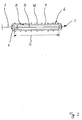
- Fig. 1
- eine perspektivische Darstellung eines Kanalabschnitts und
- Fig. 2
- einen Querschnitt durch den Kanal gemäß
Figur 1.
- Fig. 1
- a perspective view of a channel section and
- Fig. 2
- a cross section through the channel of Figure 1.
Eine Vorrichtung zum Trockenen einer auf ein verzinktes Stahlband 3 aufgebrachten
Lackschicht umfaßt einen ca. 10 bis 15 Meter (abhängig von der Bandgeschwindigkeit)
langen, senkrecht ausgerichteten Kanal, von dem der Übersichtlichkeit halber lediglich ein
einzelnes Kanalsegment 1 dargestellt ist. Der Kanal besteht aus einer Vielzahl derartiger
Kanalsegmente 1, die in Längsrichtung des Kanals hintereinander angeordnet sind und mittels
jeweils zweier an gegenüberliegenden Stirnseiten angeordneter Flansche 2 sowie geeigneter
Schrauben miteinander verbunden sind. Durch den derart gebildeten Kanal ist in dessen
Längsrichtung das lackbeschichtete Stahlband 3 mittels bekannter und in der Zeichnung nicht
näher dargestellter Führungs- und Antriebseinrichtungen geführt.A device for drying an applied on a galvanized
Das vor der Vorrichtung lackierte Stahlband 3 wird mit feuchter und flüssiger Beschichtung
am unteren stirnseitigen Ende des Kanals eingeführt und verläßt den Kanal an dessen oberer
Stirnseite mit getrockneter und ausgehärteter Lackierung. The painted before the
Der in Figur 2 dargestellte Querschnitt des Kanals ist rechteckförmig und besitzt eine lichte
Breite 4 von ca. 200 mm, und eine lichte Länge 5 von ca. 1600 mm. Die Breite des
Stahlbandes 3 beträgt ca. 1500 mm.The cross section of the channel shown in Figure 2 is rectangular and has a
Jedes Kanalsegment 1 ist von einer geschlossenen Spule 6 umgeben, die im Querschnitt
gleichfalls rechteckförmig ist und aus einem Kupferblech besteht. Die Spule 6 besitzt
lediglich eine einzige Windung und ist über Anschlußstücke 7 mit einem Inverter 8
verbunden, über den die Spule 6 mit einer hochfrequenten Spannung mit einer Frequenz von
ca. 100 kHz versorgt wird. Die Spule 6 ist in einer parallel zu der Kanallängsachse
verlaufenden Mittelebene teilbar, um die Spule 6 ausbauen und das umschlossene
Kanalsegment bedarfsweise einfach auswechseln oder reparieren zu können.Each
Wie aus Figur 2 zu ersehen ist, ist die Spule 6 äquidistant zu den Wandungen 8 des
Kanalsegments 1 angeordnet. Zwischen den aus einem auf der Innenseite mit einer
Kunststoffbeschichtung versehenen Stahlblech bestehenden Kanalwandungen 8 und der Spule
6 befindet sich ein Isoliermaterial 9, das einen unerwünschten Wärmeverlust aus dem Kanal
über die Wandungen 8 weitgehend unterbindet. An der Außenseite der Spule 6 befinden sich
mäanderförmig verlaufende und in Figur 1 der Übersichtlichkeit halber nicht dargestellte
Rohrleitungen 10, die von einer Kühlflüssigkeit durchströmt werden und für einen
Abtransport der unweigerlich in der Spule 6 entstehenden Wärme sorgen.As can be seen from Figure 2, the
Durch die Wahl von Stahlblech als Material für die Wandungen 8 des Kanals sowie durch die
entsprechende Gestaltung der Geometrie der Spule 6 ist das magnetische Feld im Bereich der
Wandungen 8 so groß, daß darin ca. 6 % bis 7 % der von der Spule 6 insgesamt abgegebenen
magnetischen Leistung umgesetzt und in Form von Wärme abgegeben wird. Je nach dem
verwendeten Material der Kanalwandungen und der Gasgeschwindigkeit im Inneren des
Kanals kann es auch sinnvoll sein, einen Anteil zwischen 7 % und 10 % der magnetischen
Spulenleistung in den Wandungen 8 in Wärme umzusetzen. Die von der Spule 6
aufgenommene elektrische Leistung beträgt im vorliegenden Fall ca. 500 kW. Davon werden
ca. 450 kW in Form magnetischer Leistung und der Rest von ca. 50kW in Form von Wärme
an die Kühlschlangen abgegeben. Bei einem Anteil zwischen 6 % und 7 % beträgt die in den
Wandungen 8 umgesetzte Wärmeleistung somit zwischen ca. 27 kW und 31,5 kW. Die
Wärmeabgabe erfolgt aufgrund der Isolierung 9, die den Kanal vollflächig auf seiner
Außenseite umgibt, vornehmlich in das Innere des Kanals, das heißt hauptsächlich in Form
von Konvektion an die den Kanal durchströmende Luft. Der weitaus größte Teil der von der
Spule 6 (hier ca. 420 kW) abgegebenen Leistung wird von dem Band 3 aufgenommen und
dort gleichfalls über Wirbelströme in Wärme umgewandelt. Diese Wärme bewirkt den
gewünschten Trocknungs- und Aushärtungsvorgang in der das Band 3 umgebenden
Lackschicht. Die zuvor beschriebene Induktion in den Wandungen 8 mit den genannten
Leistungen ist jedoch nach der vorliegenden Erfindung nicht zwingend, sondern lediglich
optional.By the choice of steel sheet as a material for the
Besonders vorteilhaft ist die Möglichkeit, die Wandungen 8 gezielt mit Hilfe des von der
Spule 6 erzeugten magnetischen Feldes aufzuheizen, wenn nach einer Stillstandsperiode die
Trocknungsvorrichtung wieder in Betrieb genommen werden soll. In diesem Falle kann die
zum Anfahren der Vorrichtung erforderliche minimale Temperatur der Wandungen 8, die je
nach dem aus dem Lack austretenden Lösungsmittel bei ca. 150°C liegt, allein durch einen
Betrieb der Spule 6 erzielt werden, ohne daß - wie beim Stand der Technik - über einen
längeren Zeitraum vorgeheizte Luft durch den Kanal hindurchgeleitet wird. Die Zeit bis zum
Wiederanfahren der Produktion wird durch das erfindungsgemäße Verfahren somit deutlich
verkürzt und die Sicherheit, das an allen Orten der Wandungen 8 eine bestimmte
Minimaltemperatur vorherrscht, erhöht.Particularly advantageous is the possibility of the
Alternativ zu der Beheizung der Wandungen 8 durch magnetische Induktion ist auch eine
Widerstandsbeheizung möglich, die vorzugsweise in Form eines auf die Außenseite der
Wandungen 8 vollflächig aufgebrachten, in den Zeichnungen jedoch nicht dargestellten
Widerstandsgewebes erfolgt.As an alternative to the heating of the
Claims (5)
Applications Claiming Priority (3)
| Application Number | Priority Date | Filing Date | Title |
|---|---|---|---|
| DE10130342A DE10130342C1 (en) | 2001-06-20 | 2001-06-20 | Method and device for drying and / or baking a coating applied to a metallic strip |
| DE10130342 | 2001-06-20 | ||
| EP02012977A EP1270088B1 (en) | 2001-06-20 | 2002-06-12 | Process for drying and/or curing a coating deposited on a metallic sheet |
Related Parent Applications (1)
| Application Number | Title | Priority Date | Filing Date |
|---|---|---|---|
| EP02012977A Division EP1270088B1 (en) | 2001-06-20 | 2002-06-12 | Process for drying and/or curing a coating deposited on a metallic sheet |
Publications (3)
| Publication Number | Publication Date |
|---|---|
| EP1508383A2 true EP1508383A2 (en) | 2005-02-23 |
| EP1508383A3 EP1508383A3 (en) | 2006-03-29 |
| EP1508383A9 EP1508383A9 (en) | 2006-08-02 |
Family
ID=7689204
Family Applications (2)
| Application Number | Title | Priority Date | Filing Date |
|---|---|---|---|
| EP02012977A Expired - Lifetime EP1270088B1 (en) | 2001-06-20 | 2002-06-12 | Process for drying and/or curing a coating deposited on a metallic sheet |
| EP04028213A Withdrawn EP1508383A3 (en) | 2001-06-20 | 2002-06-12 | Process and apparatus for drying and/or curing a coating deposited on a metallic web |
Family Applications Before (1)
| Application Number | Title | Priority Date | Filing Date |
|---|---|---|---|
| EP02012977A Expired - Lifetime EP1270088B1 (en) | 2001-06-20 | 2002-06-12 | Process for drying and/or curing a coating deposited on a metallic sheet |
Country Status (4)
| Country | Link |
|---|---|
| EP (2) | EP1270088B1 (en) |
| AT (1) | ATE367214T1 (en) |
| DE (2) | DE10130342C1 (en) |
| ES (1) | ES2289030T3 (en) |
Cited By (2)
| Publication number | Priority date | Publication date | Assignee | Title |
|---|---|---|---|---|
| EP2105212A1 (en) * | 2008-03-25 | 2009-09-30 | Gesellschaft für aero- und thermodynamische Verfahrenstechnik mbH | Device and method for heating metal strips |
| WO2009136010A1 (en) * | 2008-05-08 | 2009-11-12 | Siemens Vai Metals Technologies Sas | Method of drying and/or curing an organic coating on a continuously running metal strip, and device for implementing this method |
Citations (5)
| Publication number | Priority date | Publication date | Assignee | Title |
|---|---|---|---|---|
| GB788900A (en) * | 1954-01-19 | 1958-01-08 | Isopad Ltd | Improvements in or relating to the electrical heating of vessels and pipes |
| FR2391849A1 (en) * | 1977-05-25 | 1978-12-22 | Profil Sa Ind Financ Le | Composite metal-plastics strip mfr. - with stations for adhesive application, plastic extrusion and adhesive polymerisation |
| US4370357A (en) * | 1981-03-11 | 1983-01-25 | Cleveland Gear Company | Process of continuous metal coating |
| US5321896A (en) * | 1991-04-18 | 1994-06-21 | Alltrista Corporation | Apparatus for coating a metal substrate and for drying and curing said coating |
| EP0744222A1 (en) * | 1995-05-23 | 1996-11-27 | Stein Heurtey | Process and apparatus for coating metal strips |
Family Cites Families (2)
| Publication number | Priority date | Publication date | Assignee | Title |
|---|---|---|---|---|
| CA1309755C (en) * | 1987-03-30 | 1992-11-03 | Hiroyoshi Nozaki | Method of and apparatus for baking coating layer |
| DE19626209A1 (en) * | 1996-06-29 | 1998-01-08 | Ema Elektro Maschinen Schultze | Device and method for coating a workpiece |
-
2001
- 2001-06-20 DE DE10130342A patent/DE10130342C1/en not_active Expired - Fee Related
-
2002
- 2002-06-12 EP EP02012977A patent/EP1270088B1/en not_active Expired - Lifetime
- 2002-06-12 EP EP04028213A patent/EP1508383A3/en not_active Withdrawn
- 2002-06-12 AT AT02012977T patent/ATE367214T1/en not_active IP Right Cessation
- 2002-06-12 DE DE50210484T patent/DE50210484D1/en not_active Expired - Fee Related
- 2002-06-12 ES ES02012977T patent/ES2289030T3/en not_active Expired - Lifetime
Patent Citations (5)
| Publication number | Priority date | Publication date | Assignee | Title |
|---|---|---|---|---|
| GB788900A (en) * | 1954-01-19 | 1958-01-08 | Isopad Ltd | Improvements in or relating to the electrical heating of vessels and pipes |
| FR2391849A1 (en) * | 1977-05-25 | 1978-12-22 | Profil Sa Ind Financ Le | Composite metal-plastics strip mfr. - with stations for adhesive application, plastic extrusion and adhesive polymerisation |
| US4370357A (en) * | 1981-03-11 | 1983-01-25 | Cleveland Gear Company | Process of continuous metal coating |
| US5321896A (en) * | 1991-04-18 | 1994-06-21 | Alltrista Corporation | Apparatus for coating a metal substrate and for drying and curing said coating |
| EP0744222A1 (en) * | 1995-05-23 | 1996-11-27 | Stein Heurtey | Process and apparatus for coating metal strips |
Cited By (5)
| Publication number | Priority date | Publication date | Assignee | Title |
|---|---|---|---|---|
| EP2105212A1 (en) * | 2008-03-25 | 2009-09-30 | Gesellschaft für aero- und thermodynamische Verfahrenstechnik mbH | Device and method for heating metal strips |
| WO2009118326A1 (en) * | 2008-03-25 | 2009-10-01 | Gesellschaft für aero- und thermodynamische Verfahrenstechnik mbH | Device and method for heating metal strips |
| WO2009136010A1 (en) * | 2008-05-08 | 2009-11-12 | Siemens Vai Metals Technologies Sas | Method of drying and/or curing an organic coating on a continuously running metal strip, and device for implementing this method |
| CN102016472B (en) * | 2008-05-08 | 2013-07-24 | 西门子Vai金属科技有限公司 | Method of drying and/or curing an organic coating on a continuously running metal strip, and device for implementing this method |
| US9789514B2 (en) | 2008-05-08 | 2017-10-17 | Primetals Technologies France SAS | Method of drying and/or curing an organic coating on a continuously running metal strip, and device for implementing this method |
Also Published As
| Publication number | Publication date |
|---|---|
| DE50210484D1 (en) | 2007-08-30 |
| EP1508383A9 (en) | 2006-08-02 |
| EP1508383A3 (en) | 2006-03-29 |
| EP1270088B1 (en) | 2007-07-18 |
| ES2289030T3 (en) | 2008-02-01 |
| EP1270088A3 (en) | 2004-01-02 |
| DE10130342C1 (en) | 2003-02-06 |
| ATE367214T1 (en) | 2007-08-15 |
| EP1270088A2 (en) | 2003-01-02 |
Similar Documents
| Publication | Publication Date | Title |
|---|---|---|
| EP2726802A1 (en) | Method for heating a shaped component for a subsequent press hardening operation and continuous furnace for regionally heating a shaped component preheated to a predetermined temperature to a higher temperature | |
| DD283677A5 (en) | DEVICE FOR THE HEAT TREATMENT AND / OR DRYING OF A MATERIAL RAIL | |
| EP3282024B1 (en) | Batch furnace for annealing product and method for heat treatment | |
| DE102015112293A1 (en) | Method and apparatus for the adaption of temperature-adapting metal bands | |
| AT509596B1 (en) | METHOD FOR HEATING A SHAPE COMPONENT FOR A SUBSEQUENT PRESS HARDENING AS WELL AS CONTINUOUS FLOOR HEATING TO A HIGHER TEMPERATURE FORMED TO A PRESERVED TEMPERATURE | |
| DE1652395C3 (en) | Process and device for the continuous enamel coating of wire | |
| EP1508383A2 (en) | Process and apparatus for drying and/or curing a coating deposited on a metallic web | |
| DE1808231A1 (en) | Method and device for covering sheet metal strips or the like with heat-curing paint | |
| EP2531624B1 (en) | Device and method for heat-treating steel wires | |
| DE3118830A1 (en) | Installation for varnished-wire manufacture using the inline method | |
| DE2714791A1 (en) | PROCESS FOR CONTINUOUS HEATING OF A LONG METAL WORKPIECE, IN PARTICULAR FOR CONTINUOUS HEATING OF STEEL PIPES | |
| CH426636A (en) | Method and device for conveying material consisting of electrically conductive material, e.g. B. tapes, profiles, pipes and. Like., Preferably through a continuous furnace | |
| DE2556057C2 (en) | Method and device for heating metal strips, in particular non-ferrous metal strips | |
| DE19538364C5 (en) | Device for rapid heating of metal press studs | |
| DE2833119A1 (en) | Surfacing chipboard with films - using uniform heating enclosing all pressure rollers | |
| EP1446236A2 (en) | Method and device for the drying and/or cross-linking of a coating on a metal strip which contains solvents | |
| DE19934557A1 (en) | Cooling device for metal strips or sheets on conveyor, in which width over which coolant flows out can be set in accordance with width of strip or sheet | |
| DE102018129583A1 (en) | Inflow device | |
| EP1390551B1 (en) | Method and device for heat treatment of metal strands, especially steel strips | |
| EP1729889B1 (en) | Device for painting and drying of endless materials | |
| DE10054156C1 (en) | Process for heat treating e.g. copper foils used in the production of capacitor foils comprises guiding the foils simultaneously over two convex surfaces using gas cushions producing an egg shape cross-section | |
| DE19718530A1 (en) | Process and cooling unit for cooling hot rolled rolling stock, in particular hot wide strip | |
| AT225258B (en) | Process for enamelling wires and enameling furnace for this | |
| EP4096893A1 (en) | Device for heating and drying at least one product made from a non-ferromagnetic material | |
| DD205188A1 (en) | DEVICE FOR THE CONTROLLED COOLING OF WARM ROLLED STEEL WIRE |
Legal Events
| Date | Code | Title | Description |
|---|---|---|---|
| PUAI | Public reference made under article 153(3) epc to a published international application that has entered the european phase |
Free format text: ORIGINAL CODE: 0009012 |
|
| AC | Divisional application: reference to earlier application |
Ref document number: 1270088 Country of ref document: EP Kind code of ref document: P |
|
| AK | Designated contracting states |
Kind code of ref document: A2 Designated state(s): AT BE CH CY DE DK ES FI FR GB GR IE IT LI LU MC NL PT SE TR |
|
| PUAL | Search report despatched |
Free format text: ORIGINAL CODE: 0009013 |
|
| AK | Designated contracting states |
Kind code of ref document: A3 Designated state(s): AT BE CH CY DE DK ES FI FR GB GR IE IT LI LU MC NL PT SE TR |
|
| RAP1 | Party data changed (applicant data changed or rights of an application transferred) |
Owner name: INDUCTOTHERM COATING EQUIPMENT S.A. |
|
| 17P | Request for examination filed |
Effective date: 20060915 |
|
| AKX | Designation fees paid |
Designated state(s): AT BE CH CY DE DK ES FI FR GB GR IE IT LI LU MC NL PT SE TR |
|
| 17Q | First examination report despatched |
Effective date: 20071012 |
|
| STAA | Information on the status of an ep patent application or granted ep patent |
Free format text: STATUS: THE APPLICATION HAS BEEN WITHDRAWN |
|
| 18W | Application withdrawn |
Effective date: 20100507 |