EP1508367B1 - Dispositif pour contrôler la température dans une enceinte sous pression - Google Patents
Dispositif pour contrôler la température dans une enceinte sous pression Download PDFInfo
- Publication number
- EP1508367B1 EP1508367B1 EP03019028A EP03019028A EP1508367B1 EP 1508367 B1 EP1508367 B1 EP 1508367B1 EP 03019028 A EP03019028 A EP 03019028A EP 03019028 A EP03019028 A EP 03019028A EP 1508367 B1 EP1508367 B1 EP 1508367B1
- Authority
- EP
- European Patent Office
- Prior art keywords
- supply line
- cooling agent
- coolant
- cooling
- agent supply
- Prior art date
- Legal status (The legal status is an assumption and is not a legal conclusion. Google has not performed a legal analysis and makes no representation as to the accuracy of the status listed.)
- Expired - Lifetime
Links
Images


Classifications
-
- B—PERFORMING OPERATIONS; TRANSPORTING
- B01—PHYSICAL OR CHEMICAL PROCESSES OR APPARATUS IN GENERAL
- B01J—CHEMICAL OR PHYSICAL PROCESSES, e.g. CATALYSIS OR COLLOID CHEMISTRY; THEIR RELEVANT APPARATUS
- B01J19/00—Chemical, physical or physico-chemical processes in general; Their relevant apparatus
- B01J19/0006—Controlling or regulating processes
- B01J19/0013—Controlling the temperature of the process
-
- B—PERFORMING OPERATIONS; TRANSPORTING
- B01—PHYSICAL OR CHEMICAL PROCESSES OR APPARATUS IN GENERAL
- B01J—CHEMICAL OR PHYSICAL PROCESSES, e.g. CATALYSIS OR COLLOID CHEMISTRY; THEIR RELEVANT APPARATUS
- B01J3/00—Processes of utilising sub-atmospheric or super-atmospheric pressure to effect chemical or physical change of matter; Apparatus therefor
- B01J3/04—Pressure vessels, e.g. autoclaves
-
- B—PERFORMING OPERATIONS; TRANSPORTING
- B01—PHYSICAL OR CHEMICAL PROCESSES OR APPARATUS IN GENERAL
- B01J—CHEMICAL OR PHYSICAL PROCESSES, e.g. CATALYSIS OR COLLOID CHEMISTRY; THEIR RELEVANT APPARATUS
- B01J2219/00—Chemical, physical or physico-chemical processes in general; Their relevant apparatus
- B01J2219/00049—Controlling or regulating processes
- B01J2219/00051—Controlling the temperature
- B01J2219/00054—Controlling or regulating the heat exchange system
- B01J2219/00056—Controlling or regulating the heat exchange system involving measured parameters
- B01J2219/00058—Temperature measurement
- B01J2219/00063—Temperature measurement of the reactants
-
- B—PERFORMING OPERATIONS; TRANSPORTING
- B01—PHYSICAL OR CHEMICAL PROCESSES OR APPARATUS IN GENERAL
- B01J—CHEMICAL OR PHYSICAL PROCESSES, e.g. CATALYSIS OR COLLOID CHEMISTRY; THEIR RELEVANT APPARATUS
- B01J2219/00—Chemical, physical or physico-chemical processes in general; Their relevant apparatus
- B01J2219/00049—Controlling or regulating processes
- B01J2219/00051—Controlling the temperature
- B01J2219/00074—Controlling the temperature by indirect heating or cooling employing heat exchange fluids
- B01J2219/00076—Controlling the temperature by indirect heating or cooling employing heat exchange fluids with heat exchange elements inside the reactor
-
- B—PERFORMING OPERATIONS; TRANSPORTING
- B01—PHYSICAL OR CHEMICAL PROCESSES OR APPARATUS IN GENERAL
- B01J—CHEMICAL OR PHYSICAL PROCESSES, e.g. CATALYSIS OR COLLOID CHEMISTRY; THEIR RELEVANT APPARATUS
- B01J2219/00—Chemical, physical or physico-chemical processes in general; Their relevant apparatus
- B01J2219/00049—Controlling or regulating processes
- B01J2219/00191—Control algorithm
- B01J2219/00193—Sensing a parameter
- B01J2219/00195—Sensing a parameter of the reaction system
- B01J2219/002—Sensing a parameter of the reaction system inside the reactor
-
- B—PERFORMING OPERATIONS; TRANSPORTING
- B01—PHYSICAL OR CHEMICAL PROCESSES OR APPARATUS IN GENERAL
- B01J—CHEMICAL OR PHYSICAL PROCESSES, e.g. CATALYSIS OR COLLOID CHEMISTRY; THEIR RELEVANT APPARATUS
- B01J2219/00—Chemical, physical or physico-chemical processes in general; Their relevant apparatus
- B01J2219/00049—Controlling or regulating processes
- B01J2219/00191—Control algorithm
- B01J2219/00211—Control algorithm comparing a sensed parameter with a pre-set value
- B01J2219/00213—Fixed parameter value
-
- B—PERFORMING OPERATIONS; TRANSPORTING
- B01—PHYSICAL OR CHEMICAL PROCESSES OR APPARATUS IN GENERAL
- B01J—CHEMICAL OR PHYSICAL PROCESSES, e.g. CATALYSIS OR COLLOID CHEMISTRY; THEIR RELEVANT APPARATUS
- B01J2219/00—Chemical, physical or physico-chemical processes in general; Their relevant apparatus
- B01J2219/00049—Controlling or regulating processes
- B01J2219/00191—Control algorithm
- B01J2219/00222—Control algorithm taking actions
- B01J2219/00227—Control algorithm taking actions modifying the operating conditions
- B01J2219/00238—Control algorithm taking actions modifying the operating conditions of the heat exchange system
-
- B—PERFORMING OPERATIONS; TRANSPORTING
- B01—PHYSICAL OR CHEMICAL PROCESSES OR APPARATUS IN GENERAL
- B01J—CHEMICAL OR PHYSICAL PROCESSES, e.g. CATALYSIS OR COLLOID CHEMISTRY; THEIR RELEVANT APPARATUS
- B01J2219/00—Chemical, physical or physico-chemical processes in general; Their relevant apparatus
- B01J2219/18—Details relating to the spatial orientation of the reactor
- B01J2219/182—Details relating to the spatial orientation of the reactor horizontal
-
- F—MECHANICAL ENGINEERING; LIGHTING; HEATING; WEAPONS; BLASTING
- F28—HEAT EXCHANGE IN GENERAL
- F28D—HEAT-EXCHANGE APPARATUS, NOT PROVIDED FOR IN ANOTHER SUBCLASS, IN WHICH THE HEAT-EXCHANGE MEDIA DO NOT COME INTO DIRECT CONTACT
- F28D21/00—Heat-exchange apparatus not covered by any of the groups F28D1/00 - F28D20/00
- F28D2021/0019—Other heat exchangers for particular applications; Heat exchange systems not otherwise provided for
- F28D2021/0077—Other heat exchangers for particular applications; Heat exchange systems not otherwise provided for for tempering, e.g. with cooling or heating circuits for temperature control of elements
Definitions
- the present invention relates to a device for Temperature control of the interior of pressure vessels according to The preamble of claim 1.
- Such a device is known from DE 34 07 176 C2.
- separate coolant flows intended for the pre-cooling phase and the cooling phase these different streams being different Directions are introduced into the cooling device.
- This has the advantage that for the cooling phase and Pre-cooling phase differently sized dosing can be used, so that initially a fine control can be performed, a coarse regulation follows.
- this can be the coolant flow the pre-cooling phase in contrast to the usual introduction of the coolant of the cooling phase from below from above into the Introduce cooling device, thereby increasing the possibility an improved fine control results.
- the coolant can namely sprayed from above, e.g.
- the known device has proven itself in practice, as hereby with respect to a particularly accurate temperature control during the plateau phase and the cooling phase opposite achieved a significant improvement in the prior art becomes.
- a first Coolant supply line from below into the cooling device, wherein from the first coolant supply line, a coolant discharge line is branched off.
- the second coolant supply line leads from above into the cooling device, wherein from the second coolant supply line, a coolant return line is branched off.
- the second coolant supply line and the coolant return line therefore become from its branching point to the cooling device of formed a single line.
- US-A-3732266 describes a process for hydrogenating unsaturated oil in a container, wherein in the Be fiscaler.eine Heat exchanger coil is arranged. In this queue Steam is introduced at the upper end, while at the lower end End of water is introduced. Depending on the shift the balance between steam and water Now takes place a temperature control of the container located oil. From the steam supply line branches one Steam discharge line from, i. it's like this, too previously described prior art a single Cable entry provided in the heat exchanger coil, so that in the common line section of the supplied Steam and counteract the steam discharged.
- the invention is based on the object, a device to create the type reproduced above, the opposite the prior art, an improvement in the accuracy of Temperature control during plateau and cooling phase, in particular Pre-cooling phase, allows.
- the coolant return line and the second coolant supply line with a large distance from each other introduced into the upper region of the cooling device.
- a circulation effect of the in the cooling device obtained steam, since the steam from the area the cooling device into which the coolant is introduced is circulated to the area from which the coolant return line branches. This will produce the desired separation effect between steam and introduced coolant even further improved, so that the penetration of steam in the second coolant supply line with even greater safety is turned off.
- One Penetration of the steam into the second coolant supply line is prevented by the second coolant supply line from the side into the upper area of the cooling device opens, allowing a penetration of steam here rather unlikely.
- the flow rate of the coolant in The second coolant supply line can therefore be exactly on a predetermined value depending on the one to be provided Cooling capacity can be adjusted without this Throughput is affected by back-flowing steam.
- the cooling device suitably designed so that they have a lower Collector, an upper collector and a variety of the Includes collector connecting vertical pipes.
- the second Coolant supply line and the coolant return line open into the upper collector, while the firstdeffenzu111technisch flows into the lower collector, preferably approximately in the middle. While the coolant return line from the top of the collector, the second opens Coolant supply line in a front side of the collector.
- the second coolant supply line preferably also branches from the first coolant supply line, wherein in the second coolant supply arranged second metering valve preferably arranged above the pressure vessel is.
- the heater and the first and second metering valve are suitably connected in a temperature control loop, wherein this Temperturregel Vietnamese at least one arranged in the pressure vessel thermocouple and a temperature controller comprising the heater, the first Dosing valve and the second metering valve controls. Details The Temperturregelung will not at this point more described and are essentially in the beginning cited DE 34 07 176 C2, which hereby to the Revelation of this publication is referred to.
- valve station In a further embodiment of the invention that is second metering valve below the autoclave inside arranged a valve station. That way you can all valves are summarized in terms of location.
- the second coolant supply line near the autoclave an elevation on. This allows the cooling water in theisserffenzuSciencetechnischetechnische somehow be kept close to Autoklavenological.
- the elevation the supply line is preferably located at the nozzle of the autoclave.
- the coolant return line from above and the second coolant supply line introduced from the front or rear into the upper collector can also as the coolant return line from the top to the top Collectors are introduced, the coolant supply line preferably within the collector a 90 ° to remaining part of the coolant supply line angled tail has, so that the coolant in the horizontal direction is introduced to the collector. Also in the aforementioned Case in which the second coolant supply line introduced from the front or from the back into the upper collector is, the coolant supply takes place in the upper collector preferably horizontal.
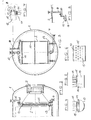
- FIG. 1 shows a horizontal pressure vessel 1, which serves as an autoclave is formed and for pressure treatment of any Serves products.
- a cooling device 2 In the pressure vessel are a cooling device 2, Heating devices (infrared radiator, not shown) and a fan 3 is arranged.
- Heating devices infrared radiator, not shown
- a fan 3 The exact structure of this Pressure vessel is in the aforementioned DE 34 07 176 C2, which is incorporated herein by reference.
- the products in the pressure vessel are a special Subjected to treatment, the temperature in the interior the pressure vessel increases in a controlled manner (heating phase), held at an approximately constant value (plateau phase) and then lowered (Vorkühlphase and Cooling phase).
- the pressure vessel interior can also during the plateau phase to be heated.
- the apparatus includes a first coolant supply line for cooling 4, in which a first metering valve 5 is arranged is and connected to a suitable coolant source is.
- the first coolant supply line opens from below into the cooling device 2. From the first coolant supply line 4, a coolant discharge line 7 branches off.
- the branches off from the first coolant supply line 4 and in a second metering valve 9 is arranged.
- the second Coolant supply line opens laterally into the upper area the cooling device 2. From the top of the cooling device 2, a coolant discharge line extends 10.
- a bypass line 6 bypasses the first metering valve. 5
- the exact structure of the cooling device 2 with the corresponding Terminals is in the following figures 2 to 8 shown.
- Figure 2 has the cooling device 2, an upper header 12 and a lower header 13, the via a plurality of vertically arranged tubes 11 with each other keep in touch.
- the first coolant supply line 4 opens approximately in the middle of the lower collector 13, while, as shown in Figure 3, the second coolant supply line 8 laterally in the upper collector 12 and the Coolant return line 10 from above into the upper collector 12 open.
- Figure 4 shows a cross section through the lower collector 13.
- the collector 13 is approximately semi-circular in section and has a closure wall 14, in the corresponding Holes 15 are formed in the plurality the vertical tubes 11 open.
- FIGS. 4 and 6 show that four parallel rows of tubes are provided, wherein the Tubes of each row offset from each other are. These vertical tubes 11 open into the upper collector 12, wherein the pipe connection 11 to the upper collector in Figure 7 is shown. Again, suitable extend Holes 17 through the lower end wall 16 of the Collector to the tubes 11.
- Figure 7 also shows the Connection of the second coolant supply 8 to the upper Collector 12, wherein the line 8 by the in FIG 3 right end wall 18 of the upper collector 12 extends.
- the Coolant is thus horizontally in the upper collector 12th introduced and penetrates through the holes 17 in the pipes 11, wherein a flow deflection takes place by 90 °.
- the coolant return line 10 flows from the top into the upper one Collector 12, and with a large distance from the line 8 in the other end of the collector.
- Figure 9 shows a schematic representation of another Embodiment of a device for temperature control the interior of pressure vessels, only changes here compared to the embodiment of Figure 1 received becomes. Compared to the embodiment of Figure 1 are in essentially two changes. For one thing second metering valve 9 in the second coolant supply line no longer above the autoclave, but inside a valve station located below the autoclave. On the other hand, in the second coolant supply line 8 an elevation 20 provided in the vicinity of the autoclave 1, around the cooling water in the coolant supply line 8 to Keep close to autoclave.
- FIG. 10 shows a longitudinal section through a further embodiment the upper header 12 of the cooling device.
- the coolant return line exits 10 the collector 12 up in the left end of the collector, while the second coolant supply 8 inserted from above into the collector 12 and a 90 ° this angled end piece 21 has, so that the coolant introduced in the horizontal direction in the upper collector 12 becomes.
Landscapes
- Chemical & Material Sciences (AREA)
- Organic Chemistry (AREA)
- Chemical Kinetics & Catalysis (AREA)
- Physical Or Chemical Processes And Apparatus (AREA)
- Motor Or Generator Cooling System (AREA)
- Commercial Cooking Devices (AREA)
- Physical Vapour Deposition (AREA)
- Filling Or Discharging Of Gas Storage Vessels (AREA)
Claims (11)
- Dispositif pour contrôler la température du volume intérieur d'enceintes sous pression avec
un élément chauffant (1) disposé dans l'enceinte sous pression ainsi qu'un élément réfrigérant (2) qui est traversé par un fluide réfrigérant,
une source pour le fluide réfrigérant qui est en communication avec l'élément réfrigérant (2) par l'intermédiaire d'une première conduite d'amenée (4) du fluide réfrigérant,
une conduite de retour (10) pour le fluide réfrigérant, une première vanne de dosage (5) disposée dans la première conduite d'amenée (4) du fluide réfrigérant et
une deuxième conduite d'amenée (8) du fluide réfrigérant pour l'élément réfrigérant (2) qui est raccordée à la source de fluide réfrigérant et dans laquelle est disposée une deuxième vanne de dosage (9) dont la section de passage est nettement plus petite que celle de la première vanne de dosage (5),
dans lequel la première conduite d'amenée (4) du fluide réfrigérant débouche par le bas et la deuxième conduite d'amenée (8) du fluide réfrigérant débouche dans la région supérieure de l'élément réfrigérant (2),
caractérisé en ce que la conduite de retour (10) pour le fluide réfrigérant et la deuxième conduite d'amenée (8) du fluide réfrigérant sont conçues comme des conduites séparées et débouchent séparément l'une de l'autre dans la région supérieure de l'élément réfrigérant (2). - Dispositif selon la revendication 1, caractérisé en ce que la conduite de retour (10) pour le fluide réfrigérant et la deuxième conduite d'amenée (8) du fluide réfrigérant sont introduites à grande distance l'une de l'autre dans la région supérieure de l'élément réfrigérant (2).
- Dispositif selon la revendication 1 ou 2, caractérisé en ce que la conduite de retour (10) pour le fluide réfrigérant est introduite par le dessus et la deuxième conduite d'amenée (8) du fluide refrigérant est introduite au-dessus par le côté dans l'élément réfrigérant (2).
- Dispositif selon une ces revendications précédentes, caractérisé en ce que l'élément réfrigérant (2) comprend un collecteur inférieur (13), un collecteur supérieur (12) et une pluralité de tubes verticaux (11) reliant les collecteurs (12, 13).
- Dispositif selon la revendication 4, caractérisé en ce que la première conduite d'amenée (4) du fluide réfrigérant est introduite de manière à peu près centrée par le bas dans le collecteur inférieur (13).
- Dispositif selon la revendication 4 ou 5, caractérisé en ce que la conduite de retour (10) pour le fluide réfrigérant est introduite par le haut et la deuxième conduite d'amenée (8) du fluide réfrigérant est introduite par le côté dans le collecteur supérieur (12).
- Dispositif selon une ces revendications précédentes, caractérisé en ce que la deuxième conduite d'amenée (8) du fluide réfrigérant se sépare de la première conduite d'amenée (4) du fluide réfrigérant et en ce que la deuxième vanne de dosage (9) est disposée au-dessus de l'enceinte sous pression (1).
- Dispositif selon une ces revendications précédentes, caractérisé en ce que l'élément chauffant et les première et deuxième vannes de dosage (5, 9) sont montés dans un circuit de régulation de la température et en ce que le circuit de régulation de la température présente au moins un thermocouple disposé dans l'enceinte sous pression (1) ainsi qu'un régulateur de température qui commande l'élément chauffant, la première vanne de dosage (5) et la deuxième vanne de dosage (9).
- Dispositif selon une des revendications 1 à 6 ou 8, caractérisé en ce que la deuxième vanne de dosage (9) est disposée en dessous de l'autoclave (1) à l'intérieur d'un poste de vanne.
- Dispositif selon une ces revendications précédentes, caractérisé en ce que la deuxième conduite d'amenée (8) du fluide réfrigérant présente une surélévation à proximité de l'autoclave (1).
- Dispositif selon une des revendications 1 à 5 ou 7 à 10, caractérisé en ce que la conduite de retour (10) pour le fluide réfrigérant est introduite par le dessus et la deuxième conduite d'amenée (8) du fluide réfrigérant est introduite par l'avant ou l'arrière dans le collecteur supérieur (12).
Priority Applications (3)
| Application Number | Priority Date | Filing Date | Title |
|---|---|---|---|
| AT03019028T ATE308379T1 (de) | 2003-08-22 | 2003-08-22 | Vorrichtung zur temperaturregelung des innenraums von druckgefässen |
| EP03019028A EP1508367B1 (fr) | 2003-08-22 | 2003-08-22 | Dispositif pour contrôler la température dans une enceinte sous pression |
| DE50301567T DE50301567D1 (de) | 2003-08-22 | 2003-08-22 | Vorrichtung zur Temperaturregelung des Innenraums von Druckgefässen |
Applications Claiming Priority (1)
| Application Number | Priority Date | Filing Date | Title |
|---|---|---|---|
| EP03019028A EP1508367B1 (fr) | 2003-08-22 | 2003-08-22 | Dispositif pour contrôler la température dans une enceinte sous pression |
Publications (2)
| Publication Number | Publication Date |
|---|---|
| EP1508367A1 EP1508367A1 (fr) | 2005-02-23 |
| EP1508367B1 true EP1508367B1 (fr) | 2005-11-02 |
Family
ID=34042887
Family Applications (1)
| Application Number | Title | Priority Date | Filing Date |
|---|---|---|---|
| EP03019028A Expired - Lifetime EP1508367B1 (fr) | 2003-08-22 | 2003-08-22 | Dispositif pour contrôler la température dans une enceinte sous pression |
Country Status (3)
| Country | Link |
|---|---|
| EP (1) | EP1508367B1 (fr) |
| AT (1) | ATE308379T1 (fr) |
| DE (1) | DE50301567D1 (fr) |
Families Citing this family (1)
| Publication number | Priority date | Publication date | Assignee | Title |
|---|---|---|---|---|
| DE102009022184A1 (de) * | 2009-05-20 | 2010-12-16 | Systec Gmbh Labor-Systemtechnik | Autoklav mit Kühlanordnung und Ventilator |
Family Cites Families (3)
| Publication number | Priority date | Publication date | Assignee | Title |
|---|---|---|---|---|
| US3732266A (en) * | 1970-04-08 | 1973-05-08 | Chemetron Corp | Hydrogenation of oils |
| DE3407176C2 (de) * | 1984-02-28 | 1986-07-10 | Maschinenbau Scholz Gmbh & Co Kg, 4420 Coesfeld | Verfahren und Vorrichtung zur Temperaturregelung des Innenraumes von Druckgefäßen |
| US6739288B1 (en) * | 2000-01-14 | 2004-05-25 | Tvl Co., Ltd. | Steam heating device |
-
2003
- 2003-08-22 DE DE50301567T patent/DE50301567D1/de not_active Expired - Lifetime
- 2003-08-22 AT AT03019028T patent/ATE308379T1/de not_active IP Right Cessation
- 2003-08-22 EP EP03019028A patent/EP1508367B1/fr not_active Expired - Lifetime
Also Published As
| Publication number | Publication date |
|---|---|
| DE50301567D1 (de) | 2005-12-08 |
| EP1508367A1 (fr) | 2005-02-23 |
| ATE308379T1 (de) | 2005-11-15 |
Similar Documents
| Publication | Publication Date | Title |
|---|---|---|
| EP3536763B1 (fr) | Système et procédé de refroidissement d'un gaz de craquage issu d'un four de craquage | |
| DE2403913A1 (de) | Verfahren und vorrichtung zum schnellen abkuehlen von behaeltern in einem heizraum | |
| DE3717521C2 (fr) | ||
| DE3031454A1 (de) | Seitenstrom-kondensationssystem und verfahren zum betreiben desselben | |
| DE69520745T2 (de) | Vorrichtung und verfahren zur kontinuierlichen kühlung von nahrungsmitteln | |
| EP1508367B1 (fr) | Dispositif pour contrôler la température dans une enceinte sous pression | |
| EP0845234B1 (fr) | Dispositif et méthode pour régler le niveau d'humidité dans un dispositif de cuisson | |
| DE2747990C3 (de) | Kaffeemaschine zum Zubereiten von Kaffee in Tassen | |
| DE2608985C3 (de) | Speisewasserbehälter für ein Dampfkraftwerk | |
| DE3023094C2 (de) | Vorrichtung zum Erzeugen von Dampf | |
| DE2655911A1 (de) | Vorrichtung zur druckbeaufschlagung | |
| DE102006043287B4 (de) | Thermoöl-Backofensystem | |
| CH642155A5 (de) | Dampferzeuger mit zwischenwand zwischen zwei brennkammern. | |
| DE4407936A1 (de) | Druckhaltevorrichtung für geschlossene Heizungs- oder Kühlkreisläufe | |
| DE102008012598B4 (de) | Kondensat-Rückführeinrichtung für eine Adsorptionskälteanlage | |
| DE3407176C2 (de) | Verfahren und Vorrichtung zur Temperaturregelung des Innenraumes von Druckgefäßen | |
| EP0387482B1 (fr) | Colonne de rectification pour la séparation des charges ayant une différence de point d'ébullition plus haute | |
| EP1528342A2 (fr) | Procédé pour séchage de matériau et dispositif pour mettre en oeuvre le procédé | |
| DE2938117C2 (fr) | ||
| DE10328518A1 (de) | Vorrichtung zum Bereitstellen von flüssigen Lebensmitteln | |
| EP0953425A1 (fr) | Dispositif et procédé de régulation en température de moules | |
| DE3416617A1 (de) | Verfahren zur waermebehandlung und vorrichtung hierfuer | |
| DE1551408C (de) | Verdunstungskühler | |
| DE2636682C3 (de) | Verfahren und Vorrichtung zum mehrstufigen Entspannungsverdampfen von Salz- oder Meerwasser zur Gewinnung von Süßwasser | |
| EP4286138A1 (fr) | Installation d'étirage et procédé de réduction de températures non uniformes et d'écoulement d'air dans une installation d'étirage de film |
Legal Events
| Date | Code | Title | Description |
|---|---|---|---|
| PUAI | Public reference made under article 153(3) epc to a published international application that has entered the european phase |
Free format text: ORIGINAL CODE: 0009012 |
|
| 17P | Request for examination filed |
Effective date: 20040720 |
|
| AK | Designated contracting states |
Kind code of ref document: A1 Designated state(s): AT BE BG CH CY CZ DE DK EE ES FI FR GB GR HU IE IT LI LU MC NL PT RO SE SI SK TR |
|
| AX | Request for extension of the european patent |
Extension state: AL LT LV MK |
|
| GRAP | Despatch of communication of intention to grant a patent |
Free format text: ORIGINAL CODE: EPIDOSNIGR1 |
|
| GRAS | Grant fee paid |
Free format text: ORIGINAL CODE: EPIDOSNIGR3 |
|
| GRAA | (expected) grant |
Free format text: ORIGINAL CODE: 0009210 |
|
| AK | Designated contracting states |
Kind code of ref document: B1 Designated state(s): AT BE BG CH CY CZ DE DK EE ES FI FR GB GR HU IE IT LI LU MC NL PT RO SE SI SK TR |
|
| AX | Request for extension of the european patent |
Extension state: AL LT LV MK |
|
| PG25 | Lapsed in a contracting state [announced via postgrant information from national office to epo] |
Ref country code: RO Free format text: LAPSE BECAUSE OF FAILURE TO SUBMIT A TRANSLATION OF THE DESCRIPTION OR TO PAY THE FEE WITHIN THE PRESCRIBED TIME-LIMIT Effective date: 20051102 Ref country code: SI Free format text: LAPSE BECAUSE OF FAILURE TO SUBMIT A TRANSLATION OF THE DESCRIPTION OR TO PAY THE FEE WITHIN THE PRESCRIBED TIME-LIMIT Effective date: 20051102 Ref country code: SK Free format text: LAPSE BECAUSE OF FAILURE TO SUBMIT A TRANSLATION OF THE DESCRIPTION OR TO PAY THE FEE WITHIN THE PRESCRIBED TIME-LIMIT Effective date: 20051102 Ref country code: IE Free format text: LAPSE BECAUSE OF FAILURE TO SUBMIT A TRANSLATION OF THE DESCRIPTION OR TO PAY THE FEE WITHIN THE PRESCRIBED TIME-LIMIT Effective date: 20051102 Ref country code: FI Free format text: LAPSE BECAUSE OF FAILURE TO SUBMIT A TRANSLATION OF THE DESCRIPTION OR TO PAY THE FEE WITHIN THE PRESCRIBED TIME-LIMIT Effective date: 20051102 Ref country code: GB Free format text: LAPSE BECAUSE OF FAILURE TO SUBMIT A TRANSLATION OF THE DESCRIPTION OR TO PAY THE FEE WITHIN THE PRESCRIBED TIME-LIMIT Effective date: 20051102 Ref country code: CZ Free format text: LAPSE BECAUSE OF FAILURE TO SUBMIT A TRANSLATION OF THE DESCRIPTION OR TO PAY THE FEE WITHIN THE PRESCRIBED TIME-LIMIT Effective date: 20051102 Ref country code: NL Free format text: LAPSE BECAUSE OF FAILURE TO SUBMIT A TRANSLATION OF THE DESCRIPTION OR TO PAY THE FEE WITHIN THE PRESCRIBED TIME-LIMIT Effective date: 20051102 Ref country code: IT Free format text: LAPSE BECAUSE OF FAILURE TO SUBMIT A TRANSLATION OF THE DESCRIPTION OR TO PAY THE FEE WITHIN THE PRESCRIBED TIME-LIMIT;WARNING: LAPSES OF ITALIAN PATENTS WITH EFFECTIVE DATE BEFORE 2007 MAY HAVE OCCURRED AT ANY TIME BEFORE 2007. THE CORRECT EFFECTIVE DATE MAY BE DIFFERENT FROM THE ONE RECORDED. Effective date: 20051102 |
|
| REG | Reference to a national code |
Ref country code: GB Ref legal event code: FG4D Free format text: NOT ENGLISH |
|
| AKX | Designation fees paid |
Designated state(s): AT BE BG CH CY CZ DE DK EE ES FI FR GB GR HU IE IT LI LU MC NL PT RO SE SI SK TR |
|
| REG | Reference to a national code |
Ref country code: CH Ref legal event code: EP |
|
| REF | Corresponds to: |
Ref document number: 50301567 Country of ref document: DE Date of ref document: 20051208 Kind code of ref document: P |
|
| PG25 | Lapsed in a contracting state [announced via postgrant information from national office to epo] |
Ref country code: BG Free format text: LAPSE BECAUSE OF FAILURE TO SUBMIT A TRANSLATION OF THE DESCRIPTION OR TO PAY THE FEE WITHIN THE PRESCRIBED TIME-LIMIT Effective date: 20060202 Ref country code: SE Free format text: LAPSE BECAUSE OF FAILURE TO SUBMIT A TRANSLATION OF THE DESCRIPTION OR TO PAY THE FEE WITHIN THE PRESCRIBED TIME-LIMIT Effective date: 20060202 Ref country code: GR Free format text: LAPSE BECAUSE OF FAILURE TO SUBMIT A TRANSLATION OF THE DESCRIPTION OR TO PAY THE FEE WITHIN THE PRESCRIBED TIME-LIMIT Effective date: 20060202 Ref country code: DK Free format text: LAPSE BECAUSE OF FAILURE TO SUBMIT A TRANSLATION OF THE DESCRIPTION OR TO PAY THE FEE WITHIN THE PRESCRIBED TIME-LIMIT Effective date: 20060202 |
|
| PG25 | Lapsed in a contracting state [announced via postgrant information from national office to epo] |
Ref country code: ES Free format text: LAPSE BECAUSE OF FAILURE TO SUBMIT A TRANSLATION OF THE DESCRIPTION OR TO PAY THE FEE WITHIN THE PRESCRIBED TIME-LIMIT Effective date: 20060213 |
|
| PG25 | Lapsed in a contracting state [announced via postgrant information from national office to epo] |
Ref country code: PT Free format text: LAPSE BECAUSE OF FAILURE TO SUBMIT A TRANSLATION OF THE DESCRIPTION OR TO PAY THE FEE WITHIN THE PRESCRIBED TIME-LIMIT Effective date: 20060403 |
|
| NLV1 | Nl: lapsed or annulled due to failure to fulfill the requirements of art. 29p and 29m of the patents act | ||
| PG25 | Lapsed in a contracting state [announced via postgrant information from national office to epo] |
Ref country code: HU Free format text: LAPSE BECAUSE OF FAILURE TO SUBMIT A TRANSLATION OF THE DESCRIPTION OR TO PAY THE FEE WITHIN THE PRESCRIBED TIME-LIMIT Effective date: 20060503 |
|
| GBV | Gb: ep patent (uk) treated as always having been void in accordance with gb section 77(7)/1977 [no translation filed] |
Effective date: 20051102 |
|
| REG | Reference to a national code |
Ref country code: IE Ref legal event code: FD4D |
|
| PG25 | Lapsed in a contracting state [announced via postgrant information from national office to epo] |
Ref country code: BE Free format text: LAPSE BECAUSE OF NON-PAYMENT OF DUE FEES Effective date: 20060831 Ref country code: MC Free format text: LAPSE BECAUSE OF NON-PAYMENT OF DUE FEES Effective date: 20060831 |
|
| PLBE | No opposition filed within time limit |
Free format text: ORIGINAL CODE: 0009261 |
|
| STAA | Information on the status of an ep patent application or granted ep patent |
Free format text: STATUS: NO OPPOSITION FILED WITHIN TIME LIMIT |
|
| 26N | No opposition filed |
Effective date: 20060803 |
|
| EN | Fr: translation not filed | ||
| PG25 | Lapsed in a contracting state [announced via postgrant information from national office to epo] |
Ref country code: FR Free format text: LAPSE BECAUSE OF FAILURE TO SUBMIT A TRANSLATION OF THE DESCRIPTION OR TO PAY THE FEE WITHIN THE PRESCRIBED TIME-LIMIT Effective date: 20061222 |
|
| PG25 | Lapsed in a contracting state [announced via postgrant information from national office to epo] |
Ref country code: AT Free format text: LAPSE BECAUSE OF NON-PAYMENT OF DUE FEES Effective date: 20060822 |
|
| BERE | Be: lapsed |
Owner name: MASCHINENBAU SCHOLZ G.M.B.H. & CO. KG Effective date: 20060831 |
|
| REG | Reference to a national code |
Ref country code: CH Ref legal event code: PL |
|
| PG25 | Lapsed in a contracting state [announced via postgrant information from national office to epo] |
Ref country code: LI Free format text: LAPSE BECAUSE OF NON-PAYMENT OF DUE FEES Effective date: 20070831 Ref country code: CH Free format text: LAPSE BECAUSE OF NON-PAYMENT OF DUE FEES Effective date: 20070831 |
|
| PG25 | Lapsed in a contracting state [announced via postgrant information from national office to epo] |
Ref country code: EE Free format text: LAPSE BECAUSE OF FAILURE TO SUBMIT A TRANSLATION OF THE DESCRIPTION OR TO PAY THE FEE WITHIN THE PRESCRIBED TIME-LIMIT Effective date: 20051102 |
|
| PG25 | Lapsed in a contracting state [announced via postgrant information from national office to epo] |
Ref country code: LU Free format text: LAPSE BECAUSE OF NON-PAYMENT OF DUE FEES Effective date: 20060822 Ref country code: TR Free format text: LAPSE BECAUSE OF FAILURE TO SUBMIT A TRANSLATION OF THE DESCRIPTION OR TO PAY THE FEE WITHIN THE PRESCRIBED TIME-LIMIT Effective date: 20051102 |
|
| PG25 | Lapsed in a contracting state [announced via postgrant information from national office to epo] |
Ref country code: FR Free format text: LAPSE BECAUSE OF FAILURE TO SUBMIT A TRANSLATION OF THE DESCRIPTION OR TO PAY THE FEE WITHIN THE PRESCRIBED TIME-LIMIT Effective date: 20051102 Ref country code: CY Free format text: LAPSE BECAUSE OF FAILURE TO SUBMIT A TRANSLATION OF THE DESCRIPTION OR TO PAY THE FEE WITHIN THE PRESCRIBED TIME-LIMIT Effective date: 20051102 |
|
| REG | Reference to a national code |
Ref country code: DE Ref legal event code: R082 Ref document number: 50301567 Country of ref document: DE Representative=s name: HAUCK PATENTANWALTSPARTNERSCHAFT MBB, DE |
|
| REG | Reference to a national code |
Ref country code: DE Ref legal event code: R082 Ref document number: 50301567 Country of ref document: DE Representative=s name: HAUCK PATENT- UND RECHTSANWAELTE, DE |
|
| PGFP | Annual fee paid to national office [announced via postgrant information from national office to epo] |
Ref country code: DE Payment date: 20221013 Year of fee payment: 20 |
|
| REG | Reference to a national code |
Ref country code: DE Ref legal event code: R071 Ref document number: 50301567 Country of ref document: DE |