EP1508019B1 - Vorrichtung zur energie- und datenspeicherung in einem gelenkten geschoss - Google Patents
Vorrichtung zur energie- und datenspeicherung in einem gelenkten geschoss Download PDFInfo
- Publication number
- EP1508019B1 EP1508019B1 EP03756283A EP03756283A EP1508019B1 EP 1508019 B1 EP1508019 B1 EP 1508019B1 EP 03756283 A EP03756283 A EP 03756283A EP 03756283 A EP03756283 A EP 03756283A EP 1508019 B1 EP1508019 B1 EP 1508019B1
- Authority
- EP
- European Patent Office
- Prior art keywords
- storage element
- energy
- projectile
- data
- energy storage
- Prior art date
- Legal status (The legal status is an assumption and is not a legal conclusion. Google has not performed a legal analysis and makes no representation as to the accuracy of the status listed.)
- Expired - Lifetime
Links
- 230000014759 maintenance of location Effects 0.000 title description 7
- 238000004146 energy storage Methods 0.000 claims abstract description 51
- 238000013500 data storage Methods 0.000 claims abstract description 16
- 230000001939 inductive effect Effects 0.000 claims abstract description 12
- 238000010304 firing Methods 0.000 claims description 2
- 238000013075 data extraction Methods 0.000 claims 1
- 239000003990 capacitor Substances 0.000 abstract description 48
- 238000004804 winding Methods 0.000 description 10
- 238000000034 method Methods 0.000 description 6
- 238000010586 diagram Methods 0.000 description 4
- 239000000126 substance Substances 0.000 description 4
- 230000015556 catabolic process Effects 0.000 description 2
- 238000006731 degradation reaction Methods 0.000 description 2
- 238000012986 modification Methods 0.000 description 2
- 230000004048 modification Effects 0.000 description 2
- 230000004913 activation Effects 0.000 description 1
- 230000006978 adaptation Effects 0.000 description 1
- 230000008878 coupling Effects 0.000 description 1
- 238000010168 coupling process Methods 0.000 description 1
- 238000005859 coupling reaction Methods 0.000 description 1
- 239000003792 electrolyte Substances 0.000 description 1
- 230000006870 function Effects 0.000 description 1
- 239000000383 hazardous chemical Substances 0.000 description 1
- 230000000977 initiatory effect Effects 0.000 description 1
- 230000008569 process Effects 0.000 description 1
- 230000001105 regulatory effect Effects 0.000 description 1
- 239000004065 semiconductor Substances 0.000 description 1
- 230000035939 shock Effects 0.000 description 1
- 125000006850 spacer group Chemical group 0.000 description 1
- 229910052715 tantalum Inorganic materials 0.000 description 1
- GUVRBAGPIYLISA-UHFFFAOYSA-N tantalum atom Chemical compound [Ta] GUVRBAGPIYLISA-UHFFFAOYSA-N 0.000 description 1
Images


Classifications
-
- F—MECHANICAL ENGINEERING; LIGHTING; HEATING; WEAPONS; BLASTING
- F42—AMMUNITION; BLASTING
- F42C—AMMUNITION FUZES; ARMING OR SAFETY MEANS THEREFOR
- F42C17/00—Fuze-setting apparatus
- F42C17/04—Fuze-setting apparatus for electric fuzes
-
- F—MECHANICAL ENGINEERING; LIGHTING; HEATING; WEAPONS; BLASTING
- F42—AMMUNITION; BLASTING
- F42C—AMMUNITION FUZES; ARMING OR SAFETY MEANS THEREFOR
- F42C15/00—Arming-means in fuzes; Safety means for preventing premature detonation of fuzes or charges
- F42C15/40—Arming-means in fuzes; Safety means for preventing premature detonation of fuzes or charges wherein the safety or arming action is effected electrically
Definitions
- the present invention pertains to energy and data transfer, and in one embodiment, the present invention pertains to energy and mission data retention in guided weapons.
- Guided projectiles including fuses, missiles and other weapons, generally need to be activated quickly.
- Conventional guided projectiles use a data interface to download mission data prior to launch and deployment.
- the mission data may include navigation data as well as initialization data for use by the projectile's Global Positioning System (GPS).
- GPS Global Positioning System
- the data may be downloaded quickly in order to launch projectiles at a rapid rate.
- Circuitry on the guided projectile is conventionally connected to a data-hold battery.
- the data-hold battery supplies power to the GPS circuitry and other circuitry prior to and during an initial portion of the projectile's deployment.
- the data-hold battery may be a chemical battery designed for a one-time initiation and may be ignited after mission data transfer by mixing or combining chemicals. Chemically ignited data-hold batteries may be dormant until activated allowing for a longer shelf life.
- data-hold batteries require the projectile be deployed relatively soon after the mission data has been transferred.
- data-hold batteries generally do not allow for recharging without degradation in performance. For example, in some combat situations, a data-hold battery may be required to hold the mission data and power the GPS circuitry for many days on one charge. If the projectile is not deployed within a certain time frame, the data-hold battery must be replaced and the mission data may have to be transferred again to the projectile.
- a disadvantage with the use of data-hold batteries in guided projectiles is safety.
- a chemically ignited data-hold battery requires the combining and/or mixing of typically hazardous chemicals.
- Another disadvantage with the use of data-hold batteries is their high-cost.
- the present invention provides an apparatus to retain energy and data in a guided projectile.
- energy and mission data for the guided projectile are transferred from a projectile setter over an inductive interface.
- the projectile may include a capacitive energy storage element to store the energy and a data storage element to store the mission data.
- Precision GPS clock circuitry of the projectile may receive power from the capacitive energy storage element during projectile loading and launching operations until a flight battery is activated.
- the capacitive energy storage element includes at least one super capacitor and a second capacitor, which may be a gun-hardened capacitor. The clock circuitry may receive power from the gun-hardened capacitor if the super capacitor fails during the launching operation.
- the capacitive energy storage element may include one-way energy transfer elements coupled between the super capacitor and the gun-hardened capacitor to help prevent discharge of the gun-hardened capacitor into the super capacitor, which may be damaged by the launch environment.
- a regulator may be coupled to an output of the capacitive storage element to regulate an output voltage.
- a method for storing energy and data may include receiving energy and data over which does not form part of the invention an interface, charging a capacitive storage element with the received energy, and storing the received data in a data storage element.
- the energy may be provided to clock circuitry until another energy source is activated.
- the energy and data may be received over an inductive interface of a guided projectile.
- the data may be mission data for the guided projectile and the other energy source may include a flight battery of the guided projectile.
- the receiving, charging and storing may be performed during projectile setting operations, and the energy may be provided to precision GPS clock circuitry subsequent to the projectile setting operations and during loading and launching operations of the guided projectile.
- the capacitive storage element may comprise a super capacitor and a secondary capacitor. Energy stored in the secondary capacitor may be provided to the clock circuitry if the super capacitor fails during the launching operation.
- FIG. 1 is a functional block diagram of a system for transferring energy and mission data in accordance with an embodiment of the present invention.
- System 100 may be used to transfer data and/or energy to an apparatus, such as a guided projectile. Guided projectiles include, for example, fuses, missiles and other guided weapons, which may be configured to use mission data.
- System 100 may include setter circuitry 102, interface 104 and projectile circuitry 106. Setter circuitry 102 may transfer mission data 108 and energy 110 to interface 104.
- Projectile circuitry 106 receives the mission data and/or energy from interface 104 and may store the mission data in data storage element 112 and the energy in energy storage element 114. Energy in energy storage element 114 may provide power to load 116 until another power source becomes available. In one embodiment, energy from energy storage element 114 may also provide power to data storage element 112 for data retention until another power source becomes available.
- Setter circuitry 102 may include other functional elements (not illustrated) to configure the data and energy for transfer across interface 104; depending on whether interface 104 is a mechanical-type interface or, for example, an inductive interface. In the case of an inductive interface, setter circuitry 102 may include functional elements to convert energy 110, for example, to an alternating current waveform. Setter circuitry 102 may also include functional elements to modulate data 108 on the waveform.
- mission data 108 may include GPS information and navigational information
- load 116 may include a precision clock, such as a GPS clock or precision oscillator.
- energy in energy storage element 114 provides power to load 116 until a flight energy source, such as a flight battery becomes available shortly after deployment of the projectile.
- Interface 104 may be a connector-less interface, such as inductive interface 118, comprised of one or more sets of windings on the projectile setter and one or more sets of windings on the projectile. Data and energy may be transferred from the one or more sets of windings of the projectile setter to the one or more sets of windings of the projectile during projectile setting operations when, for example, the projectile setter is brought in close proximity to the projectile.
- interface 104 may be an electrical or mechanical interface comprising one or more mechanical and/or electrical connectors.
- interface 104 is illustrated as a separate functional element from setter circuitry 102 and projectile circuitry 106, a first portion of interface 104 may be fabricated as part of a projectile setter, while a second portion of interface may be fabricated as part of the projectile.
- the first portion may include, for example, first sets of windings and a magnetic core located on the projectile setter
- the second portion may include, for example, second sets of windings and a magnetic core located on the projectile.
- FIG. 2 illustrates an example projectile setter and portion of a guided projectile in accordance with an embodiment of the present invention.
- Projectile setter 202 and projectile portion 204 may form connector-less interface 200 across which data and/or energy may be transferred-
- Connector-less interface 200 is one example of an inductive interface suitable for use as interface 118 (FIG. 1), although other interfaces are also suitable.
- Connector-less interface 200 may be comprised of one or more sets of windings 206 on projectile portion 204 and one or more sets of windings 208 in projectile setter 202. Windings 206 may be wound directly on magnetic cores 210 which may be separated by spacer 212. Windings 208 of setter 202, similarly, may be wound on magnetic cores (not illustrated).
- projectile portion 204 may be inserted, or disposed, into setter 202 to form a transformer allowing the transfer of energy and data.
- One suitable inductive interface may be found in U.S. Pat. No. 6,268,785 .
- FIG. 3 is a functional block diagram of projectile circuitry in accordance with an embodiment of the present invention.
- Projectile circuitry 300 may be suitable for use as projectile circuitry 106 (FIG. 1) although other circuitry is also suitable.
- Projectile circuitry 300 may include rectifier 302 to rectify a waveform received from an interface, such as interface 104 (FIG. 1), and capacitive storage element 304 to store energy extracted from the rectified waveform.
- Projectile circuitry 300 may also include data extractor 306 to extract data from a waveform received from an interface, such as interface 104 (FIG. 1), and data storage element 308 to store the extracted data.
- Regulator 310 may regulate the voltage of the waveform for data extractor 306.
- Data storage element 308 may be correspond with data storage element 112 (FIG. 1).
- Data storage element 308 may be comprised of volatile and/or nonvolatile semiconductor memory devices, as well as other elements suitable for storage of digital information including, for example, magnetic memory and magnetic storage elements.
- Capacitive energy storage element 304 may be suitable for use as energy storage element 114 (FIG. 1) although other energy storage elements are also suitable. Capacitive storage element 304 may provide an output voltage through regulator 312 for circuitry 316. Circuitry 316 may include precision clock and/or oscillator circuitry including, for example, a GPS time-synchronization clock. In one embodiment, regulator 312 may provide power to data storage element 308 for use in retaining stored data. For example, when data storage element 308 includes volatile memory, regulator 312 may provide a voltage to element 308. In one embodiment, capacitive storage element 304 may replace a data-hold battery conventionally used in guided projectiles.
- data received over an interface may include mission data for use by a guided projectile.
- energy and data may be transferred very rapidly over the interface.
- Capacitive energy storage element 304 may be charged rapidly and the mission data may be stored in data storage element 308 during projectile setting operations.
- power may be supplied to elements of projectile circuitry 300 including guidance electronics 318.
- capacitive energy storage element 304 may provide power to precision clock circuitry 316 until chemical energy storage element 320 is activated after launch.
- Chemical energy storage element 320 may be a flight battery for use in powering guidance electronics 318 and precision clock 316, among other things, during projectile deployment. In one embodiment, the flight battery may be chemically ignited during launch.
- a controller (not illustrated) may control the operations of the various functional elements of projectile circuitry 300.
- Capacitive energy storage element 304 may include primary capacitive energy storage elements, such as at least one super capacitor 322 for storing energy received from rectifier 302.
- capacitive energy storage element 304 may include a backup-energy storage element, such as gun-hardened capacitor (GHC) 324, and one-way energy transfer elements 326 between super capacitor 322 and gun-hardened capacitor 324.
- GLC gun-hardened capacitor
- Gun-hardened capacitor 324 may be a tantalum capacitor or surface mount capacitor, for example that may be gun hardened.
- One-way energy transfer elements 326 may be diodes.
- Gun-hardened capacitor 324 may serve as a back up energy storage element and in one embodiment, clock circuitry 316 may receive energy from gun-hardened capacitor 324 if super capacitor 322 fails during projectile launching (e.g., in the event super capacitor 322 may not be "gun hardened”).
- Capacitive energy storage element 304 may include other functional elements (not illustrated) to allow for charging energy storage elements 322 and 324 with a rectified waveform received from rectifier 302.
- regulator 312 may be a boost-type voltage regulator that provides an input voltage to circuitry 316 which may be greater than the voltage level received from capacitive energy storage element 304.
- only one super capacitor 322 may be needed, although more than one super capacitor may be configured in a parallel arrangement.
- regulator 312 may be a linear voltage regulator or a switching voltage regulator that provides an input voltage to circuitry 316 which may be less than or about equal to a voltage level received from capacitive energy storage element 304.
- more than one super capacitor 322 may be used, and the super capacitors may be arranged in a series configuration (as illustrated) to provide a higher combined voltage. Additional super capacitors may be added (e.g., in parallel) to provide additional current capacity.
- regulator 312 may provide a regulated output voltage to circuitry 316, which may be in the range of approximately two to four volts, for example.
- super capacitor 322 may have a high storage density and may have a capacitance of one or more Farads.
- Super capacitor 322 may be chemically inert (i.e., not including a battery or be a battery-capacitor hybrid) and may have radially configured double layer plates.
- Super capacitor 322 may also be hermetically sealed and have an electrolyte that does not freeze at temperatures of up to -43 degrees C (-45 degrees F).
- Super capacitor 322 may also be able to withstand shock forces of up to 15,000 g's and greater during projectile launching operations without failure.
- the charge and/or discharge rate of super capacitor 322 may be at least 15 Joules per second allowing super capacitor 322 to store up to 15 - 20 watts in less than two seconds, for example.
- Super capacitor 322 may be referred to as a "quick-charge" capacitor.
- projectile circuitry 300 is illustrated as having several functional elements 302 - 320, one or more of these functional elements may be combined with other functional elements and may be fabricated from various combinations of hardware and software configured elements.
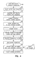
- FIG. 4 is a flow chart of a data and energy transfer procedure in accordance with an embodiment of the present invention.
- Data and energy transfer procedure 400 may be performed by a projectile setting system, such as system 100 (FIG. 1), although other systems are also suitable.
- system 100 system 100
- FIG. 4 the individual operations of procedure 400 are illustrated and described as separate operations, one or more of the individual operations may be performed concurrently and nothing requires that the operations be performed in the order illustrated.
- a projectile setter may be placed over a projectile.
- Operation 402 may establish a connector-less or an inductive interface, such as interface 118 (FIG. 1), between setter circuitry 102 (FIG. 1) and projectile circuitry 106 (FIG. 1).
- Operation 402 may alternatively establish an electro-mechanical interface.
- operation 402 may include electrically coupling the setter and projectile circuitry.
- data and/or energy are transferred over the interface from the setter circuitry to the projectile. The energy may take the form of an AC waveform and the data may be modulated on the waveform.
- a capacitive energy storage element such as energy storage element 114 (FIG. 1), may be charged.
- the charging may be performed rapidly allowing up to 25 watts or more of energy to be stored on the capacitive energy storage element in less than a few seconds.
- Operation 406 may include charging primary and back-up energy storage elements of the capacitive energy storage element.
- mission data may be stored in a data storage element, such as data storage element 112 (FIG. 1).
- operations 404 through 408 may be performed substantially simultaneously. During operations 404 through 408, power to the projectile circuitry may be supplied from an external means.
- the projectile setter may be removed from over the projectile, which may terminate the interface established in operation 402.
- operation 410 may include electrically decoupling the setter and projectile circuitry.
- a primary storage element of the capacitive energy storage element may provide energy to circuitry, such as circuitry 316 (FIG. 3), until another energy source becomes available.
- the capacitive energy storage element may provide energy to the circuitry from the time the projectile is removed from the projectile setter until after launch. This may include the time during which the projectile is transferred to a gun barrel for loading in operation 414, and the time subsequent to launch in operation 416 until a flight battery becomes available.
- the capacitive energy storage element may replace a data-hold battery used in conventional guided projectiles.
- a backup-energy storage element such as a gun-hardened capacitor
- gun-hardened capacitor 324 may provide power to the clock circuitry until the flight battery becomes available. In this situation, gun-hardened capacitor 324 may provide power to the clock circuitry for a relatively short amount of time (e.g., less than two seconds) from launch until activation of the flight battery.
- another energy source such as fight battery 320 (FIG. 3) may be activated and becomes available.
- the capacitive energy storage element may refrain from providing energy to the clock circuitry.
Landscapes
- Engineering & Computer Science (AREA)
- General Engineering & Computer Science (AREA)
- Charge And Discharge Circuits For Batteries Or The Like (AREA)
- Aiming, Guidance, Guns With A Light Source, Armor, Camouflage, And Targets (AREA)
- Peptides Or Proteins (AREA)
- Radio Relay Systems (AREA)
- Automobile Manufacture Line, Endless Track Vehicle, Trailer (AREA)
- Coin-Freed Apparatuses For Hiring Articles (AREA)
- Vending Machines For Individual Products (AREA)
- Measurement And Recording Of Electrical Phenomena And Electrical Characteristics Of The Living Body (AREA)
Claims (5)
- Einrichtung (100) zur Übertragung und Speicherung von Energie und von Daten, wobei die Einrichtung (100) einen Lenkflugkörper und eine Flugkörpereinstelleinrichtung (102) enthält, welche Missionsdaten (108) und Energie (110) auf den Lenkflugkörper über eine induktive Schnittstelle (104) überträgt; wobei der Lenkflugkörper folgendes umfasst:ein kapazitives Energiespeicherelement (114/304) zum Aufnehmen und Speichern der Energie (110), welche über die induktive Schnittstelle (104) übertragen wird;ein Datenspeicherelement (112/308) zur Aufnahme von Daten (108) welche über die induktive Schnittstelle (104) zusammen mit der Energie (110) von einem kombinierten Daten- und Energiesignal übertragen werden;eine Flugbatterie (320); undSchaltungsmittel (316) zum Aufnehmen von Leistung von dem kapazitiven Energiespeicherelement (114/304) und der Flugbatterie (320);wobei die Schaltungsmittel (316) Leistung von dem kapazitiven Energiespeicherelement (114/304) während des Ladens und des Abschusses aufnehmen und die Flugbatterie (320) nach dem Starten des Flugkörpers aktiviert wird.
- Einrichtung (100) nach Anspruch 1, bei welcher das kapazitive Energiespeicherelement (114/304) ein primäres Energiespeicherelement (322) und ein Reserveenergiespeicherelement (324) enthält und bei welcher im Falle eines Ausfalles des primären kapazitiven Energiespeicherelementes (322) das Reserveenergiespeicherelement (324) Energie an die Schaltungsmittel (316) liefern kann, bis die Flugbatterie (320) verfügbar wird.
- Einrichtung (100) nach einem der vorhergehenden Ansprüche, bei welcher der Lenkflugkörper weiter folgendes umfasst:ein Gleichrichterelement (302) zum Gleichrichten eines Signals von der Schnittstelle (104), wobei dieses Signal die Energie (110) und die Missionsdaten (108) enthält; undein Datenextraktionselement (306) zum Extrahieren der Missionsdaten (108) aus dem Signal und zur Lieferung der extrahierten Missionsdaten (108) an ein Datenspeicherelement (308).
- Einrichtung (100) nach dem vorausgehenden Anspruch, bei welcher das Gleichrichterelement (302) mit dem kapazitiven Speicherelement (304) gekoppelt ist, um die aufgenommene Energie an das kapazitive Speicherelement (304) zu liefern.
- Einrichtung (100) nach irgendeinem der vorausgehenden Ansprüche, bei welcher der Lenkflugkörper einen Regler (312) enthält, welcher an einen Ausgang des kapazitiven Speicherelementes (304) angekoppelt ist, um die Eingangsspannung der Schaltungsmittel (316) zu regeln.
Applications Claiming Priority (3)
| Application Number | Priority Date | Filing Date | Title |
|---|---|---|---|
| US158741 | 2002-05-30 | ||
| US10/158,741 US6666123B1 (en) | 2002-05-30 | 2002-05-30 | Method and apparatus for energy and data retention in a guided projectile |
| PCT/US2003/017023 WO2003102493A1 (en) | 2002-05-30 | 2003-05-30 | Method and apparatus for energy and data retention in a guided projectile |
Publications (2)
| Publication Number | Publication Date |
|---|---|
| EP1508019A1 EP1508019A1 (de) | 2005-02-23 |
| EP1508019B1 true EP1508019B1 (de) | 2007-10-31 |
Family
ID=29582746
Family Applications (1)
| Application Number | Title | Priority Date | Filing Date |
|---|---|---|---|
| EP03756283A Expired - Lifetime EP1508019B1 (de) | 2002-05-30 | 2003-05-30 | Vorrichtung zur energie- und datenspeicherung in einem gelenkten geschoss |
Country Status (8)
| Country | Link |
|---|---|
| US (1) | US6666123B1 (de) |
| EP (1) | EP1508019B1 (de) |
| AT (1) | ATE377180T1 (de) |
| AU (1) | AU2003232449A1 (de) |
| DE (1) | DE60317188T2 (de) |
| IL (2) | IL163998A0 (de) |
| RU (1) | RU2316892C2 (de) |
| WO (1) | WO2003102493A1 (de) |
Families Citing this family (35)
| Publication number | Priority date | Publication date | Assignee | Title |
|---|---|---|---|---|
| US7362659B2 (en) * | 2002-07-11 | 2008-04-22 | Action Manufacturing Company | Low current microcontroller circuit |
| US6960838B2 (en) | 2002-11-15 | 2005-11-01 | Sprint Communications Company L.P. | Power system for a telecommunication facility |
| US7525217B1 (en) * | 2002-11-15 | 2009-04-28 | Sprint Communications Company L.P. | Rectifier-super capacitor device for use in a power system for a telecommunication facility |
| EP1561270A2 (de) * | 2002-11-15 | 2005-08-10 | Sprint Communications Company, L.P. | Protonenaustauschermembran-basiertes stromspeisungssystem für eine telekommunikationsanlage |
| US6930402B1 (en) | 2003-05-15 | 2005-08-16 | Sprint Communications Company L.P. | Power system for a telecommunication facility |
| WO2005026654A2 (en) | 2003-05-08 | 2005-03-24 | Incucomm, Inc. | Weapon and weapon system employing the same |
| US7530315B2 (en) | 2003-05-08 | 2009-05-12 | Lone Star Ip Holdings, Lp | Weapon and weapon system employing the same |
| US7081687B2 (en) * | 2004-07-22 | 2006-07-25 | Sprint Communications Company L.P. | Power system for a telecommunications facility |
| DE102004036003B4 (de) * | 2004-07-23 | 2006-11-16 | Diehl Bgt Defence Gmbh & Co. Kg | Panzerhaubitze mit Programmiereinrichtung für Artilleriemunition mit Korrekturzünder |
| FR2887976A1 (fr) * | 2005-07-04 | 2007-01-05 | Lacroix Soc E | Dispositif d'allumage sans fil a resonance |
| US7690304B2 (en) * | 2005-09-30 | 2010-04-06 | Lone Star Ip Holdings, Lp | Small smart weapon and weapon system employing the same |
| US7895946B2 (en) | 2005-09-30 | 2011-03-01 | Lone Star Ip Holdings, Lp | Small smart weapon and weapon system employing the same |
| US7591225B1 (en) * | 2005-10-27 | 2009-09-22 | The United States Of America As Represented By The Secretary Of The Navy | Fuze module |
| US7557531B2 (en) * | 2005-12-19 | 2009-07-07 | Sprint Communications Company L.P. | Power system utilizing flow batteries |
| US7728458B2 (en) | 2006-01-05 | 2010-06-01 | Sprint Communications Company L.P. | Telecommunications megasite with backup power system |
| JP4865377B2 (ja) | 2006-03-28 | 2012-02-01 | 国立大学法人 新潟大学 | ヒトメガリンの測定方法 |
| US8541724B2 (en) | 2006-09-29 | 2013-09-24 | Lone Star Ip Holdings, Lp | Small smart weapon and weapon system employing the same |
| EP2069712B1 (de) | 2006-10-04 | 2016-11-23 | Raytheon Company | Induktive kraftübertragung |
| WO2008112012A2 (en) * | 2006-10-04 | 2008-09-18 | Raytheon Company | Supercapacitor power supply |
| US8117955B2 (en) | 2006-10-26 | 2012-02-21 | Lone Star Ip Holdings, Lp | Weapon interface system and delivery platform employing the same |
| US7963442B2 (en) * | 2006-12-14 | 2011-06-21 | Simmonds Precision Products, Inc. | Spin stabilized projectile trajectory control |
| FI120224B (fi) * | 2008-05-29 | 2009-07-31 | Teknoware Oy | Menetelmä ja järjestely turvavalaisimen yhteydessä |
| FR2938638A1 (fr) * | 2008-11-18 | 2010-05-21 | Nexter Munitions | Procede de programmation d'une fusee de projectile et dispositif de programmation permettant la mise en oeuvre d'un tel procede |
| ES2532333T3 (es) | 2009-04-27 | 2015-03-26 | Niigata University | Uso de megalina en orina como marcador para la detección de nefropatía por IgA |
| JP5424702B2 (ja) | 2009-04-27 | 2014-02-26 | 国立大学法人 新潟大学 | 尿中ヒトメガリンを測定することを含む腎疾患検出方法 |
| US9068803B2 (en) | 2011-04-19 | 2015-06-30 | Lone Star Ip Holdings, Lp | Weapon and weapon system employing the same |
| RU2535456C1 (ru) * | 2013-05-29 | 2014-12-10 | Шепеленко Виталий Борисович | Атташе-кейс |
| RU2535472C1 (ru) * | 2013-05-29 | 2014-12-10 | Шепеленко Виталий Борисович | Электронная пломба |
| RU2559699C2 (ru) * | 2013-05-29 | 2015-08-10 | Шепеленко Виталий Борисович | Крепежное средство для выявления несанкционированного вмешательства |
| RU2559694C2 (ru) * | 2013-05-29 | 2015-08-10 | Шепеленко Виталий Борисович | Электронное пломбировочное устройство |
| RU2535470C1 (ru) * | 2013-05-29 | 2014-12-10 | Шепеленко Виталий Борисович | Электронная пломба |
| RU2535471C1 (ru) * | 2013-05-29 | 2014-12-10 | Шепеленко Виталий Борисович | Электронная пломба |
| SE541930C2 (en) * | 2017-09-28 | 2020-01-07 | Bae Systems Bofors Ab | Method and system for inductive programming of a fuze |
| US10852116B2 (en) * | 2019-03-06 | 2020-12-01 | Bae Systems Information And Electronic Systems Integration Inc. | Fuze setter interface for powering and programming a fuze on a guided projectile |
| TR2024007974A1 (tr) * | 2024-06-24 | 2025-10-21 | Roketsan Roket Sanayi Ve Ticaret Anonim Sirketi | Firlaticida şarj edi̇len enerji̇ kaynaği kullanan füze |
Family Cites Families (17)
| Publication number | Priority date | Publication date | Assignee | Title |
|---|---|---|---|---|
| US4424745A (en) * | 1972-03-24 | 1984-01-10 | The United States Of America As Represented By The Secretary Of The Navy | Digital timer fuze |
| DE2316967C3 (de) * | 1973-04-05 | 1975-11-13 | Kugelfischer Georg Schaefer & Co, 8720 Schweinfurt | Biegungsfreie Walzenlagerung |
| US4091734A (en) * | 1977-02-22 | 1978-05-30 | The United States Of America As Represented By The Secretary Of The Navy | Aircraft to weapon fuze communication link |
| US4454815A (en) * | 1981-09-21 | 1984-06-19 | The United States Of America As Represented By The Secretary Of The Army | Reprogrammable electronic fuze |
| DE3150172A1 (de) * | 1981-12-18 | 1983-06-30 | Brown, Boveri & Cie Ag, 6800 Mannheim | Einrichtung zum einstellen und/oder ueberwachen der wirkungsweise eines geschosszuenders |
| US4837556A (en) * | 1985-04-15 | 1989-06-06 | Kabushiki Kaisha Nihon Denzai Kogyo Kenkyusho | Signal transmission device |
| US4736681A (en) * | 1985-11-15 | 1988-04-12 | Motorola, Inc. | Electronic encoder |
| DE3822255A1 (de) * | 1988-07-01 | 1990-01-04 | Wegmann & Co | Wurfsystem fuer wurfkoerper, wie nebelkerzen und dergleichen |
| JP2714976B2 (ja) * | 1989-03-02 | 1998-02-16 | 防衛庁技術研究本部長 | 電気信管のデータ通信方法 |
| RU2064160C1 (ru) * | 1991-03-04 | 1996-07-20 | Специальное конструкторское бюро "Ротор" | Установщик электронно-дистанционного взрывателя с индуктивной цепью управления |
| US5119715A (en) * | 1991-07-02 | 1992-06-09 | Raytheon Company | Time delay fuze |
| US5343795A (en) * | 1991-11-07 | 1994-09-06 | General Electric Co. | Settable electronic fuzing system for cannon ammunition |
| DE4234878C2 (de) | 1992-10-16 | 1995-03-30 | Deutsche Aerospace | Verfahren zur autonomen Lagesteuerung von Lenkflugkörpern |
| DE59608912D1 (de) * | 1995-09-28 | 2002-04-25 | Contraves Pyrotec Ag | Verfahren und Vorrichtung zum Programmieren von Zeitzündern von Geschossen |
| US5994998A (en) * | 1997-05-29 | 1999-11-30 | 3Com Corporation | Power transfer apparatus for concurrently transmitting data and power over data wires |
| JP3537328B2 (ja) | 1998-11-12 | 2004-06-14 | 松下電器産業株式会社 | 水没確認装置及びそれを用いた携帯端末装置 |
| US6268785B1 (en) * | 1998-12-22 | 2001-07-31 | Raytheon Company | Apparatus and method for transferring energy across a connectorless interface |
-
2002
- 2002-05-30 US US10/158,741 patent/US6666123B1/en not_active Expired - Lifetime
-
2003
- 2003-05-30 RU RU2004138802/02A patent/RU2316892C2/ru not_active IP Right Cessation
- 2003-05-30 EP EP03756283A patent/EP1508019B1/de not_active Expired - Lifetime
- 2003-05-30 IL IL16399803A patent/IL163998A0/xx unknown
- 2003-05-30 DE DE60317188T patent/DE60317188T2/de not_active Expired - Lifetime
- 2003-05-30 AU AU2003232449A patent/AU2003232449A1/en not_active Abandoned
- 2003-05-30 AT AT03756283T patent/ATE377180T1/de active
- 2003-05-30 WO PCT/US2003/017023 patent/WO2003102493A1/en not_active Ceased
-
2004
- 2004-09-09 IL IL163998A patent/IL163998A/en active IP Right Grant
Also Published As
| Publication number | Publication date |
|---|---|
| ATE377180T1 (de) | 2007-11-15 |
| RU2004138802A (ru) | 2005-07-20 |
| US6666123B1 (en) | 2003-12-23 |
| IL163998A (en) | 2010-06-30 |
| RU2316892C2 (ru) | 2008-02-10 |
| AU2003232449A1 (en) | 2003-12-19 |
| US20030221546A1 (en) | 2003-12-04 |
| IL163998A0 (en) | 2005-12-18 |
| EP1508019A1 (de) | 2005-02-23 |
| DE60317188D1 (de) | 2007-12-13 |
| DE60317188T2 (de) | 2008-07-31 |
| WO2003102493A1 (en) | 2003-12-11 |
Similar Documents
| Publication | Publication Date | Title |
|---|---|---|
| US6666123B1 (en) | Method and apparatus for energy and data retention in a guided projectile | |
| McNab et al. | Development of a naval railgun | |
| US3500746A (en) | Weapon system with an electronic time fuze | |
| US7946209B2 (en) | Launcher for a projectile having a supercapacitor power supply | |
| US4424745A (en) | Digital timer fuze | |
| US8286554B2 (en) | Electrically initiated inertial igniters for thermal batteries and the like | |
| US10615695B1 (en) | High voltage generation for ESAD munition fuzing circuitry | |
| US5078051A (en) | Ammunition data transmission system | |
| US10529995B2 (en) | Reusable resettable retriggerable rebuildable squibless missile battery | |
| US6634298B1 (en) | Fireset for a low energy exploding foil initiator: SCR driven MOSFET switch | |
| US6865989B2 (en) | Electronic self-destruct device | |
| US6202532B1 (en) | Data exchange system and method for ammunition rounds | |
| US3722416A (en) | Fuze function selection and firing system | |
| Seifert et al. | Integrated electric propulsion systems for small satellites | |
| JP2004036984A (ja) | 電子雷管 | |
| WO2026005740A1 (en) | Missile using energy source charged in the launcher | |
| RU2718477C2 (ru) | Источник питания для управляемых артиллерийских и реактивных снарядов | |
| US6675715B1 (en) | Electronic projectile fuse | |
| PL234192B1 (pl) | Zapalnik elektroniczny programowalny, zwłaszcza do nabojów granatnikowych i układ zasilająco-sterujący zapalnika elektronicznego programowalnego, zwłaszcza do nabojów granatnikowych | |
| RU2233420C2 (ru) | Способ обеспечения электропитанием бортовой аппаратуры управляемой ракеты и управляемая ракета в транспортно-пусковом контейнере для его осуществления | |
| CN217692759U (zh) | 制导武器供电系统 | |
| KR100927223B1 (ko) | 위성덮개분리용 비접촉식 폭발성 브릿지와이어 기폭장치 | |
| USH1751H (en) | High-G telemetry controller | |
| WO2025075536A1 (en) | A device for protecting a circuit during activation of a reserve battery and a method for protecting a circuit during activation of a reserve battery comprised in a device | |
| Marsh | Military applications of lithium batteries |
Legal Events
| Date | Code | Title | Description |
|---|---|---|---|
| PUAI | Public reference made under article 153(3) epc to a published international application that has entered the european phase |
Free format text: ORIGINAL CODE: 0009012 |
|
| 17P | Request for examination filed |
Effective date: 20040928 |
|
| AK | Designated contracting states |
Kind code of ref document: A1 Designated state(s): AT BE BG CH CY CZ DE DK EE ES FI FR GB GR HU IE IT LI LU MC NL PT RO SE SI SK TR |
|
| AX | Request for extension of the european patent |
Extension state: AL LT LV MK |
|
| RIN1 | Information on inventor provided before grant (corrected) |
Inventor name: MAUGANS, ERIC, C. Inventor name: ADAMS, TOVAN, L. Inventor name: LANGE, W., NORMAN, JR. |
|
| DAX | Request for extension of the european patent (deleted) | ||
| RTI1 | Title (correction) |
Free format text: APPARATUS FOR ENERGY AND DATA RETENTION IN A GUIDED PROJECTILE |
|
| GRAP | Despatch of communication of intention to grant a patent |
Free format text: ORIGINAL CODE: EPIDOSNIGR1 |
|
| GRAS | Grant fee paid |
Free format text: ORIGINAL CODE: EPIDOSNIGR3 |
|
| GRAA | (expected) grant |
Free format text: ORIGINAL CODE: 0009210 |
|
| AK | Designated contracting states |
Kind code of ref document: B1 Designated state(s): AT BE BG CH CY CZ DE DK EE ES FI FR GB GR HU IE IT LI LU MC NL PT RO SE SI SK TR |
|
| REG | Reference to a national code |
Ref country code: GB Ref legal event code: FG4D |
|
| REG | Reference to a national code |
Ref country code: IE Ref legal event code: FG4D |
|
| REG | Reference to a national code |
Ref country code: CH Ref legal event code: EP |
|
| REF | Corresponds to: |
Ref document number: 60317188 Country of ref document: DE Date of ref document: 20071213 Kind code of ref document: P |
|
| NLV1 | Nl: lapsed or annulled due to failure to fulfill the requirements of art. 29p and 29m of the patents act | ||
| PG25 | Lapsed in a contracting state [announced via postgrant information from national office to epo] |
Ref country code: NL Free format text: LAPSE BECAUSE OF FAILURE TO SUBMIT A TRANSLATION OF THE DESCRIPTION OR TO PAY THE FEE WITHIN THE PRESCRIBED TIME-LIMIT Effective date: 20071031 Ref country code: LI Free format text: LAPSE BECAUSE OF FAILURE TO SUBMIT A TRANSLATION OF THE DESCRIPTION OR TO PAY THE FEE WITHIN THE PRESCRIBED TIME-LIMIT Effective date: 20071031 Ref country code: CH Free format text: LAPSE BECAUSE OF FAILURE TO SUBMIT A TRANSLATION OF THE DESCRIPTION OR TO PAY THE FEE WITHIN THE PRESCRIBED TIME-LIMIT Effective date: 20071031 Ref country code: ES Free format text: LAPSE BECAUSE OF FAILURE TO SUBMIT A TRANSLATION OF THE DESCRIPTION OR TO PAY THE FEE WITHIN THE PRESCRIBED TIME-LIMIT Effective date: 20080211 Ref country code: SE Free format text: LAPSE BECAUSE OF FAILURE TO SUBMIT A TRANSLATION OF THE DESCRIPTION OR TO PAY THE FEE WITHIN THE PRESCRIBED TIME-LIMIT Effective date: 20080131 |
|
| REG | Reference to a national code |
Ref country code: CH Ref legal event code: PL |
|
| PG25 | Lapsed in a contracting state [announced via postgrant information from national office to epo] |
Ref country code: BG Free format text: LAPSE BECAUSE OF FAILURE TO SUBMIT A TRANSLATION OF THE DESCRIPTION OR TO PAY THE FEE WITHIN THE PRESCRIBED TIME-LIMIT Effective date: 20080131 Ref country code: SI Free format text: LAPSE BECAUSE OF FAILURE TO SUBMIT A TRANSLATION OF THE DESCRIPTION OR TO PAY THE FEE WITHIN THE PRESCRIBED TIME-LIMIT Effective date: 20071031 Ref country code: PT Free format text: LAPSE BECAUSE OF FAILURE TO SUBMIT A TRANSLATION OF THE DESCRIPTION OR TO PAY THE FEE WITHIN THE PRESCRIBED TIME-LIMIT Effective date: 20080331 |
|
| PG25 | Lapsed in a contracting state [announced via postgrant information from national office to epo] |
Ref country code: AT Free format text: LAPSE BECAUSE OF FAILURE TO SUBMIT A TRANSLATION OF THE DESCRIPTION OR TO PAY THE FEE WITHIN THE PRESCRIBED TIME-LIMIT Effective date: 20071031 |
|
| ET | Fr: translation filed | ||
| PG25 | Lapsed in a contracting state [announced via postgrant information from national office to epo] |
Ref country code: CZ Free format text: LAPSE BECAUSE OF FAILURE TO SUBMIT A TRANSLATION OF THE DESCRIPTION OR TO PAY THE FEE WITHIN THE PRESCRIBED TIME-LIMIT Effective date: 20071031 Ref country code: DK Free format text: LAPSE BECAUSE OF FAILURE TO SUBMIT A TRANSLATION OF THE DESCRIPTION OR TO PAY THE FEE WITHIN THE PRESCRIBED TIME-LIMIT Effective date: 20071031 |
|
| PG25 | Lapsed in a contracting state [announced via postgrant information from national office to epo] |
Ref country code: SK Free format text: LAPSE BECAUSE OF FAILURE TO SUBMIT A TRANSLATION OF THE DESCRIPTION OR TO PAY THE FEE WITHIN THE PRESCRIBED TIME-LIMIT Effective date: 20071031 Ref country code: RO Free format text: LAPSE BECAUSE OF FAILURE TO SUBMIT A TRANSLATION OF THE DESCRIPTION OR TO PAY THE FEE WITHIN THE PRESCRIBED TIME-LIMIT Effective date: 20071031 Ref country code: BE Free format text: LAPSE BECAUSE OF FAILURE TO SUBMIT A TRANSLATION OF THE DESCRIPTION OR TO PAY THE FEE WITHIN THE PRESCRIBED TIME-LIMIT Effective date: 20071031 |
|
| PLBE | No opposition filed within time limit |
Free format text: ORIGINAL CODE: 0009261 |
|
| STAA | Information on the status of an ep patent application or granted ep patent |
Free format text: STATUS: NO OPPOSITION FILED WITHIN TIME LIMIT |
|
| 26N | No opposition filed |
Effective date: 20080801 |
|
| PG25 | Lapsed in a contracting state [announced via postgrant information from national office to epo] |
Ref country code: MC Free format text: LAPSE BECAUSE OF NON-PAYMENT OF DUE FEES Effective date: 20080531 |
|
| PG25 | Lapsed in a contracting state [announced via postgrant information from national office to epo] |
Ref country code: GR Free format text: LAPSE BECAUSE OF FAILURE TO SUBMIT A TRANSLATION OF THE DESCRIPTION OR TO PAY THE FEE WITHIN THE PRESCRIBED TIME-LIMIT Effective date: 20080201 |
|
| PG25 | Lapsed in a contracting state [announced via postgrant information from national office to epo] |
Ref country code: FI Free format text: LAPSE BECAUSE OF FAILURE TO SUBMIT A TRANSLATION OF THE DESCRIPTION OR TO PAY THE FEE WITHIN THE PRESCRIBED TIME-LIMIT Effective date: 20071031 |
|
| PG25 | Lapsed in a contracting state [announced via postgrant information from national office to epo] |
Ref country code: IE Free format text: LAPSE BECAUSE OF NON-PAYMENT OF DUE FEES Effective date: 20080530 Ref country code: EE Free format text: LAPSE BECAUSE OF FAILURE TO SUBMIT A TRANSLATION OF THE DESCRIPTION OR TO PAY THE FEE WITHIN THE PRESCRIBED TIME-LIMIT Effective date: 20071031 |
|
| PG25 | Lapsed in a contracting state [announced via postgrant information from national office to epo] |
Ref country code: CY Free format text: LAPSE BECAUSE OF FAILURE TO SUBMIT A TRANSLATION OF THE DESCRIPTION OR TO PAY THE FEE WITHIN THE PRESCRIBED TIME-LIMIT Effective date: 20071031 |
|
| PG25 | Lapsed in a contracting state [announced via postgrant information from national office to epo] |
Ref country code: HU Free format text: LAPSE BECAUSE OF FAILURE TO SUBMIT A TRANSLATION OF THE DESCRIPTION OR TO PAY THE FEE WITHIN THE PRESCRIBED TIME-LIMIT Effective date: 20080501 Ref country code: LU Free format text: LAPSE BECAUSE OF NON-PAYMENT OF DUE FEES Effective date: 20080530 |
|
| PG25 | Lapsed in a contracting state [announced via postgrant information from national office to epo] |
Ref country code: TR Free format text: LAPSE BECAUSE OF FAILURE TO SUBMIT A TRANSLATION OF THE DESCRIPTION OR TO PAY THE FEE WITHIN THE PRESCRIBED TIME-LIMIT Effective date: 20071031 |
|
| REG | Reference to a national code |
Ref country code: FR Ref legal event code: PLFP Year of fee payment: 14 |
|
| REG | Reference to a national code |
Ref country code: FR Ref legal event code: PLFP Year of fee payment: 15 |
|
| REG | Reference to a national code |
Ref country code: FR Ref legal event code: PLFP Year of fee payment: 16 |
|
| PGFP | Annual fee paid to national office [announced via postgrant information from national office to epo] |
Ref country code: IT Payment date: 20190527 Year of fee payment: 17 Ref country code: DE Payment date: 20190514 Year of fee payment: 17 |
|
| PGFP | Annual fee paid to national office [announced via postgrant information from national office to epo] |
Ref country code: FR Payment date: 20190410 Year of fee payment: 17 |
|
| PGFP | Annual fee paid to national office [announced via postgrant information from national office to epo] |
Ref country code: GB Payment date: 20190529 Year of fee payment: 17 |
|
| REG | Reference to a national code |
Ref country code: DE Ref legal event code: R119 Ref document number: 60317188 Country of ref document: DE |
|
| GBPC | Gb: european patent ceased through non-payment of renewal fee |
Effective date: 20200530 |
|
| PG25 | Lapsed in a contracting state [announced via postgrant information from national office to epo] |
Ref country code: FR Free format text: LAPSE BECAUSE OF NON-PAYMENT OF DUE FEES Effective date: 20200531 Ref country code: GB Free format text: LAPSE BECAUSE OF NON-PAYMENT OF DUE FEES Effective date: 20200530 |
|
| PG25 | Lapsed in a contracting state [announced via postgrant information from national office to epo] |
Ref country code: DE Free format text: LAPSE BECAUSE OF NON-PAYMENT OF DUE FEES Effective date: 20201201 |
|
| PG25 | Lapsed in a contracting state [announced via postgrant information from national office to epo] |
Ref country code: IT Free format text: LAPSE BECAUSE OF NON-PAYMENT OF DUE FEES Effective date: 20200530 |