EP1507150A1 - Vorrichtung und Verfahren zur Abstandsbestimmung von Objekten - Google Patents
Vorrichtung und Verfahren zur Abstandsbestimmung von Objekten Download PDFInfo
- Publication number
- EP1507150A1 EP1507150A1 EP04018080A EP04018080A EP1507150A1 EP 1507150 A1 EP1507150 A1 EP 1507150A1 EP 04018080 A EP04018080 A EP 04018080A EP 04018080 A EP04018080 A EP 04018080A EP 1507150 A1 EP1507150 A1 EP 1507150A1
- Authority
- EP
- European Patent Office
- Prior art keywords
- transmitting devices
- objects
- motor vehicle
- signals
- alternating operation
- Prior art date
- Legal status (The legal status is an assumption and is not a legal conclusion. Google has not performed a legal analysis and makes no representation as to the accuracy of the status listed.)
- Withdrawn
Links
Images
Classifications
-
- G—PHYSICS
- G01—MEASURING; TESTING
- G01S—RADIO DIRECTION-FINDING; RADIO NAVIGATION; DETERMINING DISTANCE OR VELOCITY BY USE OF RADIO WAVES; LOCATING OR PRESENCE-DETECTING BY USE OF THE REFLECTION OR RERADIATION OF RADIO WAVES; ANALOGOUS ARRANGEMENTS USING OTHER WAVES
- G01S15/00—Systems using the reflection or reradiation of acoustic waves, e.g. sonar systems
- G01S15/88—Sonar systems specially adapted for specific applications
- G01S15/93—Sonar systems specially adapted for specific applications for anti-collision purposes
- G01S15/931—Sonar systems specially adapted for specific applications for anti-collision purposes of land vehicles
-
- G—PHYSICS
- G01—MEASURING; TESTING
- G01S—RADIO DIRECTION-FINDING; RADIO NAVIGATION; DETERMINING DISTANCE OR VELOCITY BY USE OF RADIO WAVES; LOCATING OR PRESENCE-DETECTING BY USE OF THE REFLECTION OR RERADIATION OF RADIO WAVES; ANALOGOUS ARRANGEMENTS USING OTHER WAVES
- G01S13/00—Systems using the reflection or reradiation of radio waves, e.g. radar systems; Analogous systems using reflection or reradiation of waves whose nature or wavelength is irrelevant or unspecified
- G01S13/87—Combinations of radar systems, e.g. primary radar and secondary radar
-
- G—PHYSICS
- G01—MEASURING; TESTING
- G01S—RADIO DIRECTION-FINDING; RADIO NAVIGATION; DETERMINING DISTANCE OR VELOCITY BY USE OF RADIO WAVES; LOCATING OR PRESENCE-DETECTING BY USE OF THE REFLECTION OR RERADIATION OF RADIO WAVES; ANALOGOUS ARRANGEMENTS USING OTHER WAVES
- G01S13/00—Systems using the reflection or reradiation of radio waves, e.g. radar systems; Analogous systems using reflection or reradiation of waves whose nature or wavelength is irrelevant or unspecified
- G01S13/88—Radar or analogous systems specially adapted for specific applications
- G01S13/93—Radar or analogous systems specially adapted for specific applications for anti-collision purposes
- G01S13/931—Radar or analogous systems specially adapted for specific applications for anti-collision purposes of land vehicles
-
- G—PHYSICS
- G01—MEASURING; TESTING
- G01S—RADIO DIRECTION-FINDING; RADIO NAVIGATION; DETERMINING DISTANCE OR VELOCITY BY USE OF RADIO WAVES; LOCATING OR PRESENCE-DETECTING BY USE OF THE REFLECTION OR RERADIATION OF RADIO WAVES; ANALOGOUS ARRANGEMENTS USING OTHER WAVES
- G01S15/00—Systems using the reflection or reradiation of acoustic waves, e.g. sonar systems
- G01S15/87—Combinations of sonar systems
-
- G—PHYSICS
- G01—MEASURING; TESTING
- G01S—RADIO DIRECTION-FINDING; RADIO NAVIGATION; DETERMINING DISTANCE OR VELOCITY BY USE OF RADIO WAVES; LOCATING OR PRESENCE-DETECTING BY USE OF THE REFLECTION OR RERADIATION OF RADIO WAVES; ANALOGOUS ARRANGEMENTS USING OTHER WAVES
- G01S13/00—Systems using the reflection or reradiation of radio waves, e.g. radar systems; Analogous systems using reflection or reradiation of waves whose nature or wavelength is irrelevant or unspecified
- G01S13/88—Radar or analogous systems specially adapted for specific applications
- G01S13/93—Radar or analogous systems specially adapted for specific applications for anti-collision purposes
- G01S13/931—Radar or analogous systems specially adapted for specific applications for anti-collision purposes of land vehicles
- G01S2013/932—Radar or analogous systems specially adapted for specific applications for anti-collision purposes of land vehicles using own vehicle data, e.g. ground speed, steering wheel direction
-
- G—PHYSICS
- G01—MEASURING; TESTING
- G01S—RADIO DIRECTION-FINDING; RADIO NAVIGATION; DETERMINING DISTANCE OR VELOCITY BY USE OF RADIO WAVES; LOCATING OR PRESENCE-DETECTING BY USE OF THE REFLECTION OR RERADIATION OF RADIO WAVES; ANALOGOUS ARRANGEMENTS USING OTHER WAVES
- G01S13/00—Systems using the reflection or reradiation of radio waves, e.g. radar systems; Analogous systems using reflection or reradiation of waves whose nature or wavelength is irrelevant or unspecified
- G01S13/88—Radar or analogous systems specially adapted for specific applications
- G01S13/93—Radar or analogous systems specially adapted for specific applications for anti-collision purposes
- G01S13/931—Radar or analogous systems specially adapted for specific applications for anti-collision purposes of land vehicles
- G01S2013/9327—Sensor installation details
- G01S2013/93276—Sensor installation details in the windshield area
-
- G—PHYSICS
- G01—MEASURING; TESTING
- G01S—RADIO DIRECTION-FINDING; RADIO NAVIGATION; DETERMINING DISTANCE OR VELOCITY BY USE OF RADIO WAVES; LOCATING OR PRESENCE-DETECTING BY USE OF THE REFLECTION OR RERADIATION OF RADIO WAVES; ANALOGOUS ARRANGEMENTS USING OTHER WAVES
- G01S13/00—Systems using the reflection or reradiation of radio waves, e.g. radar systems; Analogous systems using reflection or reradiation of waves whose nature or wavelength is irrelevant or unspecified
- G01S13/88—Radar or analogous systems specially adapted for specific applications
- G01S13/93—Radar or analogous systems specially adapted for specific applications for anti-collision purposes
- G01S13/931—Radar or analogous systems specially adapted for specific applications for anti-collision purposes of land vehicles
- G01S2013/9327—Sensor installation details
- G01S2013/93277—Sensor installation details in the lights
Definitions
- the present invention relates to a device and a method for Distance determination of objects with a number of transmit devices and an associated receiving device.
- Generic devices and methods for distance determination work mostly according to the transit time principle, whereby that of the transmitting device emitted signal is reflected on an object and the reflected Signal from the receiving device immediately adjacent to the transmitting device is detected. Based on the speed and duration of the Signal is then determined the distance of the object.
- the document DE 40 04 530 C2 describes a method and a device for optical reflected light detection for detecting a Object, whereby the receiver signals of two overlapping in a measuring room, bundled with each other directed light transmitter-reflex light receiver beam paths measured separately and relative to each other be evaluated.
- the two light emitter of a Low-frequency oscillator periodically alternately controlled, so that the neighboring reflex light receiver from where the two are each other Overlying beam paths impinge on the object with equal intensity receives uniform or unmodulated light and from there, where more Light from one light transmitter or the other light emitter on the object impinges, receives uneven or appropriately modulated light. Based on the modulation of the light, the position of the object can be determined.
- an object of the present invention to provide an improved Device and an improved method for distance determination to conceive of objects that require the use of multiple Transmitting devices and a receiving device at any different Allow positions, especially when used in Vehicles to monitor the largest possible area and the distance To objects in this environment as closely as possible determine.
- the object is achieved by a control device, which operates the number of transmitting devices alternately, so that the emitted from the various transmitting devices Signals and reflected signals on one of the objects in dependence on the alternating operation clearly identifiable by the receiving device are.
- a control device which operates the number of transmitting devices alternately, so that the emitted from the various transmitting devices Signals and reflected signals on one of the objects in dependence on the alternating operation clearly identifiable by the receiving device are.
- the transmitting devices and the receiving device are spatially arranged separately from each other.
- the Transmitting devices and the receiving device no large unit, but several small units, making them much easier favorable locations can be accommodated in a motor vehicle.
- the transmitting devices can in the field of headlights be positioned while the receiving device in the area the inner mirror is positioned.
- the transmitting devices preferably have different transmission powers or opening angle. In this way, the transmitting devices to different distance ranges as well as solid angle ranges of the Vehicle environment are designed, which while driving and / or especially during parking for the distance determination of objects are relevant.
- the transmitting devices are positioned so that transmitting devices with a large transmission power below transmitter devices with a low transmission power. This way, in particular when used in a motor vehicle takes into account that the transmitting devices with large transmission power not at eye level There is no health risk to other road users represent.
- the transmitting devices are positioned so that their opening angles at least partially overlap, thus the environment of the motor vehicle is completely monitored and no dead solid angle occur.
- the object is achieved by having a number of transmitting devices and an associated receiving unit, the number of Transmitting devices operated by a control device alternately so that those emitted by the various broadcast facilities Signals and reflected signals on one of the objects in dependence on the alternating operation uniquely identified by the receiving device become.
- a first embodiment of the invention sees the alternating operation the transmitting devices, that the transmitting devices each with be operated consecutively for the same period. This simplifies the assignment and evaluation of the reflected signals.
- the alternating operation of the transmitting devices suggest that the transmitting devices depending on their Transmission power to be operated.
- the transmitting devices operated with low ranges more frequently than the transmitting devices with long ranges.
- the alternating operation provides that the transmitting devices operated in dependence on their opening angle become.
- the transmitting devices which act on the average solid angle area in front of the motor vehicle operated more frequently than those transmitting devices, which the lateral Apply solid angle areas in front of the motor vehicle.
- the alternating operation of the transmitting devices may provide that the transmitting devices each depending on the position of a Object operated in the environment of a motor vehicle. For example before detecting an object in the vehicle environment, the transmitting devices be activated with long range and be detected after capture an object in the vehicle environment automatically the transmitting devices activated with a short range.
- the alternate operation of the transmitters may provide that the transmitting devices depending on the speed be operated of the motor vehicle. So be at high speeds of the motor vehicle automatically the transmitting devices with large Range activated, while at low speeds the transmitting devices be activated with a short range.
- the different methods of alternating operation the various transmitting devices can also be combined, whereby the method for distance determination of objects in the environment a motor vehicle is extremely flexible and the results achieved are very precise at the same time.
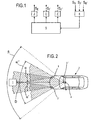
- the device for distance determination of objects 1 operates according to the transit time method.
- the apparatus accommodated in a motor vehicle 2 in the present example comprises three spatially separated transmitting devices 3, 3 ', 3 "and a common receiving device 4 for the transmitting devices 3, 3', 3".
- the transmitting devices 3, 3 ', 3 transmitmit their Signals S E , S E 'or S E "of a known signal speed successively in the environment of the motor vehicle 2 from.
- the timing of the emitted signals S E, S E ', S E ", the signals S E, S E while in always the same manner.', S E" are repeated on an object 1 in the vehicle environment, , reflected, for example, on another motor vehicle ahead or on a stationary obstacle and the reflected signals S R , S R 'and S R "are received by the receiving device 4.
- the transit time of the emitted and reflected signals S E , S E ' , S E “, S R , S R 'S R " is proportional to the distance D between the object 1 and the motor vehicle 2.
- the transmitting devices 3, 3', 3 By operating the transmitting devices 3, 3', 3 "alternately, so that only one of the transmitting devices outputs a signal S E , S E 'or S E ", the signals S E , S E ', S E “, S R , S R ', S R "of the transmitting devices 3, 3', 3" can not be mutually exclusive superimpose and can be received by the receiving device 4 signals S R , S R 'and S R "are assigned in a unique way to the relevant transmitting device 3, 3 'or 3" and an error-free distance determination is achieved.
- 1 and 2 are each a total of three transmitting devices 3, 3 ', 3 " provided, wherein two of the transmitting devices 3, 3 'in the lower part of Headlight of the motor vehicle 2 are arranged and the third transmitting device 3 "in the upper region of the interior mirror of the motor vehicle 2 is arranged. Also in the area of the interior mirror and immediately adjacent to the third transmitting device 3 "is the common receiving device 4 arranged.
- the two lower transmitting devices 3, 3 'each have a large transmission power and a relatively small opening angle ⁇ , ⁇ 'of about 20 degrees to the far range before illuminate the motor vehicle 2 in a narrow solid angle, while the upper transmitting device 3 "has a lower transmitting power and a large opening angle ⁇ "of about 60 degrees to the near zone before illuminate the motor vehicle 2 in a wide solid angle.
- the opening angle ⁇ , ⁇ ', ⁇ "of the various Transmitting devices 3, 3 ', 3 " so that the environment of interest is completely illuminated in front of the motor vehicle 2.
- the receiving device 4 positioned in the motor vehicle 2 has a large aperture angle ⁇ of approximately 80 degrees, which is only caused by the immediately adjacent third transmitting device 3" is insignificantly limited.
- the transmitting devices 3, 3 ', 3 "and the receiving device 4 are interconnected via a control device 5.
- This control device 5 controls the alternating operation of the transmitting devices 3, 3', 3" and evaluates the signals S R , S received by the receiving device 4 R ', S R "off, provided that the evaluation of the received signals S R , S R ', S R " does not take place directly in the receiving device 4.
- the control device 5 For the alternating operation of the transmitting devices 3, 3 ', 3 "it is provided that the control device 5, the individual transmitting devices 3, 3', 3" with the same time consecutively, depending on their transmission power, depending on their opening angle, depending on the position of the object 1 in the environment of the motor vehicle 2 and / or in dependence on the speed of the motor vehicle 2 drives, in any case always only one of the three transmitting devices 3, 3 ', 3 "works and no superpositions of the emitted or reflected signals S E. , S E ', S E ", S R , S R ', S R " occur.
Landscapes
- Engineering & Computer Science (AREA)
- Radar, Positioning & Navigation (AREA)
- Remote Sensing (AREA)
- Physics & Mathematics (AREA)
- Computer Networks & Wireless Communication (AREA)
- General Physics & Mathematics (AREA)
- Electromagnetism (AREA)
- Acoustics & Sound (AREA)
- Optical Radar Systems And Details Thereof (AREA)
- Radar Systems Or Details Thereof (AREA)
Abstract
Description
- Fig. 1
- Eine erfindungsgemäße Vorrichtung in schematischer Darstellung; und
- Fig. 2
- ein Kraftfahrzeug mit der darin integrierten Vorrichtung in vereinfachter Darstellung.
- 1
- Objekt
- 2
- Kraftfahrzeug
- 3, 3', 3''
- Sendeeinrichtung
- 4
- Empfangseinrichtung
- 5
- Steuereinrichtung
- D
- Abstand zwischen 1 und 2
- N
- Anzahl von 3, 3', 3"
- SE, SE', SE"
- emittiertes Signal
- SR, SR', SR"
- reflektiertes Signal
- α, α', α"
- Öffnungswinkel von 3, 3', 3"
- β
- Öffnungswinkel von 4
Claims (11)
- Vorrichtung zur Abstandsbestimmung von Objekten, mitdadurch gekennzeichnet, dasseiner Anzahl von Sendeeinrichtungen sowieeiner zugeordneten Empfangseinrichtung,
eine Steuereinrichtung (5) vorgesehen ist, welche die Anzahl (N) von Sendeeinrichtungen (3, 3', 3") alternierend betreibt, so dass die von den verschiedenen Sendeeinrichtungen (3, 3', 3") emittierten Signale (SE, SE', SE") und an einem der Objekte (1) reflektierten Signale (SR, SR', SR") in Abhängigkeit von dem alternierenden Betrieb eindeutig durch die Empfangseinrichtung (4) identifizierbar sind. - Vorrichtung nach Anspruch 1, dadurch gekennzeichnet, dass die Sendeeinrichtungen (3, 3', 3") und die Empfangseinrichtung (4) räumlich getrennt voneinander angeordnet sind.
- Vorrichtung nach Anspruch 1 oder 2, dadurch gekennzeichnet, dass die Sendeeinrichtungen (3, 3', 3") unterschiedliche Sendeleistungen bzw. Öffnungswinkel (α, α', α") aufweisen.
- Vorrichtung nach einem der Ansprüche 1 bis 3, dadurch gekennzeichnet, dass die Sendeeinrichtungen (3, 3', 3") so positioniert sind, dass sich die Sendeeinrichtungen (3, 3') mit einer großen Sendeleistung unterhalb der Sendeeinrichtungen (3") mit einer geringen Sendeleistung befinden.
- Vorrichtung nach einem der Ansprüche 1 bis 4, dadurch gekennzeichnet, dass die Anzahl (N) von Sendeeinrichtungen (3, 3', 3"), so positioniert sind, dass sich ihre Öffnungswinkel (α, α', α") zumindest teilweise überlappen.
- Verfahren zur Abstandsbestimmung von Objekten mittels einer Anzahl von Sendeeinrichtungen sowie einer zugeordneten Empfangseinheit,
dadurch gekennzeichnet, dass
die Anzahl (N) von Sendeeinrichtungen (3, 3', 3") durch eine Steuereinrichtung (5) alternierend betrieben werden, so dass die von den verschiedenen Sendeeinrichtungen (3, 3', 3") emittierten Signale (SE, SE', SE") und an einem der Objekte (1) reflektierten Signale (SR, SR', SR") in Abhängigkeit von dem alternierenden Betrieb eindeutig durch die Empfangseinheit (4) identifiziert werden. - Verfahren nach Anspruch 6, dadurch gekennzeichnet, dass der alternierende Betrieb der Sendeeinrichtungen (3, 3', 3") vorsieht, dass die Sendeeinrichtungen (3, 3', 3") jeweils mit gleicher Zeitdauer nacheinander betrieben werden.
- Verfahren nach Anspruch 6 oder 7, dadurch gekennzeichnet, dass der alternierende Betrieb der Sendeeinrichtungen (3, 3', 3") vorsieht, dass die Sendeeinrichtungen (3, 3', 3") jeweils in Abhängigkeit von ihrer Sendeleistung betrieben werden.
- Verfahren nach einem der Ansprüche 6 bis 8, dadurch gekennzeichnet, dass der alternierende Betrieb der Sendeeinrichtungen (3, 3', 3") vorsieht, dass die Sendeeinrichtungen (3, 3', 3") jeweils in Abhängigkeit von ihrem Öffnungswinkel (α, α', α") betrieben werden.
- Verfahren nach einem der Ansprüche 6 bis 9, dadurch gekennzeichnet, dass der alternierende Betrieb der Sendeeinrichtung (3, 3', 3") vorsieht, dass die Sendeeinrichtungen (3, 3', 3") jeweils in Abhängigkeit von der Position der Objekte (1) im Umfeld eines Kraftfahrzeuges (2) betrieben werden.
- Verfahren nach einem der Ansprüche 6 bis 10, dadurch gekennzeichnet, dass der alternierende Betrieb der Sendeeinrichtungen (3, 3', 3") vorsieht, dass die Sendeeinrichtungen (3, 3', 3") jeweils in Abhängigkeit von der Geschwindigkeit eines Kraftfahrzeuges (2) betrieben werden.
Applications Claiming Priority (2)
| Application Number | Priority Date | Filing Date | Title |
|---|---|---|---|
| DE10336682A DE10336682A1 (de) | 2003-08-09 | 2003-08-09 | Vorrichtung und Verfahren zur Abstandsbestimmung von Objekten |
| DE10336682 | 2003-08-09 |
Publications (1)
| Publication Number | Publication Date |
|---|---|
| EP1507150A1 true EP1507150A1 (de) | 2005-02-16 |
Family
ID=33560286
Family Applications (1)
| Application Number | Title | Priority Date | Filing Date |
|---|---|---|---|
| EP04018080A Withdrawn EP1507150A1 (de) | 2003-08-09 | 2004-07-30 | Vorrichtung und Verfahren zur Abstandsbestimmung von Objekten |
Country Status (2)
| Country | Link |
|---|---|
| EP (1) | EP1507150A1 (de) |
| DE (1) | DE10336682A1 (de) |
Cited By (1)
| Publication number | Priority date | Publication date | Assignee | Title |
|---|---|---|---|---|
| WO2017148845A1 (de) * | 2016-03-04 | 2017-09-08 | Valeo Schalter Und Sensoren Gmbh | Optische messvorrichtung für kraftfahrzeuge und verfahren zum betrieb einer solchen |
Families Citing this family (4)
| Publication number | Priority date | Publication date | Assignee | Title |
|---|---|---|---|---|
| DE102006004019B3 (de) * | 2006-01-27 | 2007-03-08 | Audi Ag | PMD-System und Verfahren zur Abstandsmessung von einem Objekt |
| DE102009045558B4 (de) * | 2009-10-12 | 2021-07-15 | pmdtechnologies ag | Kamerasystem |
| DE102013007859B3 (de) * | 2013-05-08 | 2014-09-25 | Audi Ag | Time-of-Flight-System mit räumlich voneinander getrennten Sendeeinrichtungen und Verfahren zur Abstandsmessung von einem Objekt |
| DE102014114723A1 (de) * | 2014-10-10 | 2016-04-14 | Valeo Schalter Und Sensoren Gmbh | Optoelektronische Detektionseinrichtung, Verfahren zum Betrieb einer solchen Detektionseinrichtung und Kraftfahrzeug mit einer solchen Detektionseinrichtung |
Citations (4)
| Publication number | Priority date | Publication date | Assignee | Title |
|---|---|---|---|---|
| US5920521A (en) * | 1996-04-19 | 1999-07-06 | Mayser Gmbh & Co. | Ultrasound area surveillance system |
| DE10007501A1 (de) * | 2000-02-18 | 2001-09-13 | Daimler Chrysler Ag | Verfahren und Vorrichtung zur Erfassung und Überwachung einer Mehrzahl von vorausfahrenden Fahrzeugen |
| US6509863B2 (en) * | 1999-08-06 | 2003-01-21 | Visteon Corporation | Radar-field-of-view enhancement method and apparatus for matching field-of-view to desired detection zone |
| GB2378597A (en) * | 2001-08-06 | 2003-02-12 | Roke Manor Research | Object Detection Device |
Family Cites Families (4)
| Publication number | Priority date | Publication date | Assignee | Title |
|---|---|---|---|---|
| DE3244358C2 (de) * | 1982-12-01 | 1984-10-04 | Daimler-Benz Ag, 7000 Stuttgart | Einrichtung zur Erfassung von Hindernissen als Rangierhilfe beim Einparken oder Wenden eines Kraftfahrzeuges |
| JPS60256076A (ja) * | 1984-06-01 | 1985-12-17 | Nissan Motor Co Ltd | 先行車検出装置 |
| DE4004530C2 (de) * | 1990-02-14 | 1999-07-29 | Stefan Reich | Optische Abstandsmessung |
| DE10012522C2 (de) * | 2000-03-15 | 2002-09-26 | Leuze Electronic Gmbh & Co | Distanzsensor |
-
2003
- 2003-08-09 DE DE10336682A patent/DE10336682A1/de not_active Ceased
-
2004
- 2004-07-30 EP EP04018080A patent/EP1507150A1/de not_active Withdrawn
Patent Citations (4)
| Publication number | Priority date | Publication date | Assignee | Title |
|---|---|---|---|---|
| US5920521A (en) * | 1996-04-19 | 1999-07-06 | Mayser Gmbh & Co. | Ultrasound area surveillance system |
| US6509863B2 (en) * | 1999-08-06 | 2003-01-21 | Visteon Corporation | Radar-field-of-view enhancement method and apparatus for matching field-of-view to desired detection zone |
| DE10007501A1 (de) * | 2000-02-18 | 2001-09-13 | Daimler Chrysler Ag | Verfahren und Vorrichtung zur Erfassung und Überwachung einer Mehrzahl von vorausfahrenden Fahrzeugen |
| GB2378597A (en) * | 2001-08-06 | 2003-02-12 | Roke Manor Research | Object Detection Device |
Cited By (1)
| Publication number | Priority date | Publication date | Assignee | Title |
|---|---|---|---|---|
| WO2017148845A1 (de) * | 2016-03-04 | 2017-09-08 | Valeo Schalter Und Sensoren Gmbh | Optische messvorrichtung für kraftfahrzeuge und verfahren zum betrieb einer solchen |
Also Published As
| Publication number | Publication date |
|---|---|
| DE10336682A1 (de) | 2005-03-10 |
Similar Documents
| Publication | Publication Date | Title |
|---|---|---|
| EP1267177A1 (de) | Verfahren und Vorrichtung zur Lokalisierung von Objekten im Raum | |
| DE3420004C2 (de) | ||
| EP3485290B1 (de) | Verfahren und system zur abtastung eines objekts | |
| DE19507956C2 (de) | Einrichtung zur Bestimmung des Fahrzeugabstandes von einer seitlichen Fahrbahnmarkierung | |
| EP3649479A1 (de) | System zum detektieren eines bewegten objekts | |
| DE10143504A1 (de) | Überwachungsverfahren und optoelektronischer Sensor | |
| DE102007013266A1 (de) | Radarvorrichtung | |
| DE3028077A1 (de) | Radar-ueberwachungseinrichtung zur verwendung in fahrzeugen | |
| DE10360889A1 (de) | System mit zwei oder mehr Sensoren | |
| EP1516301A1 (de) | Verfahren und vorrichtung zur fahrerinformation bzw. zur reaktion bei verlassen der fahrspur | |
| DE3222263A1 (de) | Abstands-warnsystem fuer kraftfahrzeuge | |
| DE10007501A1 (de) | Verfahren und Vorrichtung zur Erfassung und Überwachung einer Mehrzahl von vorausfahrenden Fahrzeugen | |
| DE102016115705B4 (de) | Verfahren für die Erfassung von Objekten in der Umgebung eines Fahrzeugs | |
| DE69218334T2 (de) | Vorrichtung zur Wahrnehmung und Identifizierung von Hubschraubern | |
| DE102017109073A1 (de) | Informationsanzeigevorrichtung | |
| DE19842827A1 (de) | Precrashsensierungssystem | |
| DE10348216B4 (de) | Objekterfassungssystem für ein Fahrzeug | |
| EP1484620A1 (de) | Vorrichtung und Verfahren zum Erkennen des Konturverlaufes eines Hindernisses | |
| EP0775921A1 (de) | Vorrichtung zur Abstandsbestimmung von Fahrzeugen | |
| WO2018060100A1 (de) | Optischer sensor zur entfernungs- und/oder geschwindigkeitsmessung, system zur mobilitätsüberwachung von autonomen fahrzeugen und verfahren zur mobilitätsüberwachung von autonomen fahrzeugen | |
| DE102020007760A1 (de) | Verfahren zur Klassifizierung von Fahrbahnmarkierungen und Fahrzeug | |
| DE19910743B4 (de) | Verfahren und Vorrichtung zur Erzeugung von mehrfarbigen Mustern | |
| DE10249003B4 (de) | Verfahren und Vorrichtung zur Signalisierung eines zeitlich und räumlich variierenden Gefahrenpotentials für den ein technisches Gerät oder eine Maschine bedienenden Operator | |
| DE102016213983A1 (de) | Steuer- und Auswerteeinheit, LiDAR-System, Arbeitsvorrichtung und Verfahren zum Steuern | |
| WO2022243089A1 (de) | Verfahren zum betreiben einer detektionsvorrichtung, detektionsvorrichtung und fahrzeug mit wenigstens einer detektionsvorrichtung |
Legal Events
| Date | Code | Title | Description |
|---|---|---|---|
| PUAI | Public reference made under article 153(3) epc to a published international application that has entered the european phase |
Free format text: ORIGINAL CODE: 0009012 |
|
| AK | Designated contracting states |
Kind code of ref document: A1 Designated state(s): AT BE BG CH CY CZ DE DK EE ES FI FR GB GR HU IE IT LI LU MC NL PL PT RO SE SI SK TR |
|
| AX | Request for extension of the european patent |
Extension state: AL HR LT LV MK |
|
| 17P | Request for examination filed |
Effective date: 20050816 |
|
| AKX | Designation fees paid |
Designated state(s): DE FR GB IT |
|
| 17Q | First examination report despatched |
Effective date: 20060824 |
|
| APBK | Appeal reference recorded |
Free format text: ORIGINAL CODE: EPIDOSNREFNE |
|
| APBN | Date of receipt of notice of appeal recorded |
Free format text: ORIGINAL CODE: EPIDOSNNOA2E |
|
| APBR | Date of receipt of statement of grounds of appeal recorded |
Free format text: ORIGINAL CODE: EPIDOSNNOA3E |
|
| APAV | Appeal reference deleted |
Free format text: ORIGINAL CODE: EPIDOSDREFNE |
|
| APBT | Appeal procedure closed |
Free format text: ORIGINAL CODE: EPIDOSNNOA9E |
|
| STAA | Information on the status of an ep patent application or granted ep patent |
Free format text: STATUS: THE APPLICATION HAS BEEN WITHDRAWN |
|
| 18W | Application withdrawn |
Effective date: 20150622 |