EP1506906A2 - Pillar element of a vehicle body - Google Patents
Pillar element of a vehicle body Download PDFInfo
- Publication number
- EP1506906A2 EP1506906A2 EP04018346A EP04018346A EP1506906A2 EP 1506906 A2 EP1506906 A2 EP 1506906A2 EP 04018346 A EP04018346 A EP 04018346A EP 04018346 A EP04018346 A EP 04018346A EP 1506906 A2 EP1506906 A2 EP 1506906A2
- Authority
- EP
- European Patent Office
- Prior art keywords
- column
- recesses
- column element
- element according
- foot
- Prior art date
- Legal status (The legal status is an assumption and is not a legal conclusion. Google has not performed a legal analysis and makes no representation as to the accuracy of the status listed.)
- Granted
Links
Images

Classifications
-
- B—PERFORMING OPERATIONS; TRANSPORTING
- B62—LAND VEHICLES FOR TRAVELLING OTHERWISE THAN ON RAILS
- B62D—MOTOR VEHICLES; TRAILERS
- B62D25/00—Superstructure or monocoque structure sub-units; Parts or details thereof not otherwise provided for
- B62D25/04—Door pillars ; windshield pillars
-
- B—PERFORMING OPERATIONS; TRANSPORTING
- B62—LAND VEHICLES FOR TRAVELLING OTHERWISE THAN ON RAILS
- B62D—MOTOR VEHICLES; TRAILERS
- B62D21/00—Understructures, i.e. chassis frame on which a vehicle body may be mounted
- B62D21/15—Understructures, i.e. chassis frame on which a vehicle body may be mounted having impact absorbing means, e.g. a frame designed to permanently or temporarily change shape or dimension upon impact with another body
- B62D21/157—Understructures, i.e. chassis frame on which a vehicle body may be mounted having impact absorbing means, e.g. a frame designed to permanently or temporarily change shape or dimension upon impact with another body for side impacts
Definitions
- the invention relates to a pillar element on a motor vehicle body after Preamble of claim 1.
- Column elements such as B-pillars, consist predominantly of at least an inner panel and an outer panel together, which in turn deep-drawn as well firmly connected to each other at their edges, preferably welded and accordingly form a largely closed hollow profile.
- the object of the invention is a simple improvement in the prior art and to provide a cost-effective pillar element on a motor vehicle body, which in case of a crash, especially in a side crash, as far as possible Protective function for the occupants of the passenger compartment, especially above the Maintains foot area and is also suitable to crash energy effectively absorb respectively in adjacent body components to initiate.
- the recesses are such formed to be due to a certain in the vehicle transverse direction on the Column element acting force component "F" such a deformation of the Column foot cause that longitudinally or largely in the longitudinal direction of Column element directed opposite end edges or end edge portions the recesses slide past each other in the manner of a flow joint.
- one or more end edges and / or End edge portions of the recesses straight or curved or rounded are formed. It is further considered appropriate that opposite arranged end edges of one or more recesses at least partially formed cross-offset to each other.
- the number of Recesses, the distribution of the same in the area of the column foot and possibly above Moreover, and the dimensions of the recesses are further selected such that during the Deformation of the column base Cracks in the profile material and / or collapse the pillar structure are largely avoided.
- the present invention is particularly suitable for use on a column element in the form of a B-pillar application Find.
- the proposed column element has the essential with respect to conventional Advantage that with extremely little effort an effective occupant protection above the foot area is achieved by the deformation of the column element due of a side crash focused primarily on the foot area and the load on the connection flange of the column member to the adjacent component of Floor group of the motor vehicle, such as an outer side member (sill), minimized becomes.
- a Abutting force "F” in the vehicle transverse direction (y-direction) in a deformation of the lower Area of the column element in the vehicle longitudinal direction (x-direction) implemented become. It was also found in extensive experiments that the Resistance to said abutment force "F” reducing cracking as much as possible could be avoided and the stability of the column element in particular remained largely preserved above the foot.
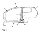
- Fig. 1 shows, as already demonstrated above, very schematically the side view of Shell of the passenger compartment of a motor vehicle.
- a middle one Column element 1 shown in the form of a B-pillar, which in turn incorporating front and rear pillar members 2; 3 (A, C pillars) a roof structure 4 is supported and at least on a component of the floor assembly 5 of the motor vehicle, in this case a lower outer side member thereof, which may be a sill, connected.
- said column element 1 is in the form of the B-pillar at least from an inner panel 6 and an outer panel 7, which at their Edges, forming a largely closed hollow profile, firmly connected, preferably welded.
- the column element 1 in the form of the B-pillar at least in his lower portion of the outer panel 7, also referred to as a column foot 8, d. h., in which Column section near the connection area to the floor assembly of the motor vehicle, in the present case near the connection area to the side member (sill), in which general life experience during a side crash with an accident participant Automotive abutment forces are initiated, one or more, the rigidity of the Column element 1 defined in the affected section reducing slit-shaped Recesses 9 on.
- a recess 9 is shown, which in turn is designed such that the same due to a certain in the vehicle transverse direction on the column element.
- 1 acting force component "F” causes such a deformation of the column foot 8, that in the longitudinal direction or largely in the longitudinal direction of the column element.
- slot-shaped recesses 9 are the End edges 10 formed in a straight line or almost straight.
- slot-shaped recesses 9 see on the other hand curved respectively rounded end edges 10 and / or End edge portions, so that the recesses 9 egg-shaped or as elongated ellipses may be formed (not shown).
- FIGS. 2 to 4 The effect of said recesses 9 will be described in more detail below by FIGS. 2 to 4 be illustrated.
- the column member 1 has a slight outwardly curved structure.
- a certain resulting from a side impact force component "F" forces in the y direction acts on the column foot 8, as shown by the present slot-shaped recess 9 gem.
- Figs. 3 and 4 in the period t 1 (15ms after force) to t n (50ms after force) allows a transverse contraction of the material of the column foot 8 in such a way that directed in the longitudinal direction of the column member 1 and opposite end edges 10 of the recess Slide 9 in the x direction or in the vehicle longitudinal direction past each other or slide over each other.
- the column element 1 extends in its entirety.
- the present invention is based on a column element 1 in the form of a B-pillar has been described in detail and preferably applicable to these.
- the special Training the column foot 8 also for any other column elements 2; 3 at one Motor vehicle body, in which acting in the vehicle transverse direction abutment forces intercepted the pedestal 8 and in deformations thereof in the vehicle longitudinal direction be implemented.
Abstract
Description
Die Erfindung betrifft ein Säulenelement an einer Kraftfahrzeugkarosserie nach dem
Oberbegriff des Anspruchs 1.The invention relates to a pillar element on a motor vehicle body after
Preamble of
Säulenelemente, wie beispielsweise B-Säulen, setzen sich überwiegend aus wenigstens einem Innenblech und einem Außenblech zusammen, die ihrerseits tiefgezogen sowie untereinander an ihren Rändern fest verbunden, vorzugsweise verschweißt sind und demgemäss ein weitestgehend geschlossenes Hohlprofil ausbilden.Column elements, such as B-pillars, consist predominantly of at least an inner panel and an outer panel together, which in turn deep-drawn as well firmly connected to each other at their edges, preferably welded and accordingly form a largely closed hollow profile.
Im wesentlichen dienen sie zur Abstützung der Dachstruktur des Kraftfahrzeugs und stellen des Weiteren die direkte Verbindung zur Bodengruppe desselben her.Essentially they serve to support the roof structure of the motor vehicle and furthermore provide the direct connection to the floorboard of the same.
Bekannte Gestaltungen besagter Säulenelemente verfügen über die Länge derselben gesehen über Querschnittsveränderungen, indem dieselben im oberen Anschlussbereich an die Dachstruktur und im unteren Anschlussbereich an beispielsweise äußere Längsträger, auch Schweller bezeichnet, in ihrem Querschnitt verstärkt ausgebildet sind, wobei im Bereich der Fenster im Verhältnis zum oberen und unteren Anschlussbereich der Querschnitt geringer ausgeführt ist.Known designs of said column elements have the same length seen about cross-sectional changes by the same in the upper connection area to the roof structure and in the lower connection area to, for example, outer Side members, also called sills, are reinforced in their cross-section, being in the area of the windows relative to the upper and lower terminal area the cross-section is made smaller.
Im Falle eines Seitencrashs wird sich ein betroffenes Säulenelement in seinem mittleren Bereich, auch als festigkeitsunstetiger Bereich bezeichnet, nach innen in die Fahrgastzelle bewegen, welches zu vermeiden gilt.In the event of a side crash, an affected column element will become in its middle Area, also referred to as strength-resistant area, inwards into the Move the passenger compartment, which should be avoided.
In der Praxis werden die verschiedensten Lösungen vorgeschlagen, um ein Einknicken des Säulenelementes in seinem, für Fahrzeuginsassen kritischen mittleren Bereich zu vermeiden.In practice, various solutions are proposed to buckling of the pillar member in its central area critical for vehicle occupants avoid.
Danach wird durch die EP 1 180 470 A1 vorgeschlagen, das Werkstoffgefüge des
Säulenfußes einer B-Säule durch Wärmebehandlung mit einer hohen Duktilität und
oberhalb dieses Bereiches ein Werkstoffgefüge mit hoher Festigkeit einzustellen.
Hierdurch soll ein optimales Crashverhalten der B-Säule realisierbar sein, da der
Säulenfuß infolge der eingestellten hohen Duktilität eher als der obere Bereich dazu
neigt, unter der Einwirkung von äußeren Kräften ohne Rissbildung sich bleibend zu
verformen.It is then proposed by
Diese Maßnahme mag sicherlich den gewünschten Erfolg bringen, jedoch wird diese als äußerst aufwendig und kostenintensiv eingeschätzt.This measure may certainly bring the desired success, but this is as estimated very expensive and expensive.
Eine gleichgelagerte Entwicklungsrichtung wird mit der EP 0 816 520 B1 beschritten, wobei auch hier durch gezielte Wärmebehandlungen ein kontinuierlich sich änderndes Festigkeitsverteilungsprofil gebildet werden soll, nämlich mittig der B-Säule ein hohe Festigkeit vorgesehen wird, die zu den Enden hin kontinuierlich abnimmt.An identically stored development direction is followed by EP 0 816 520 B1, Here, too, by means of targeted heat treatments a continuously changing Strength distribution profile to be formed, namely in the middle of the B-pillar a high Strength is provided, which decreases continuously towards the ends.
Des Weiteren ist es bekannt, festigkeitsunstetige Bereiche an Motorhauben zu schaffen, indem versteifende Spriegel durch Langlöcher für gezielte Deformationen der Motorhaube im Falle eines Zusammenpralls mit beispielsweise einem Fußgänger geschwächt ausgebildet werden (DE 101 09 663 A1).Furthermore, it is known to provide strength-resistant areas on hoods, by stiffening bow through slots for targeted deformations of the Bonnet in the event of a collision with, for example, a pedestrian be formed weakened (DE 101 09 663 A1).
Ferner ist es aus der DE 33 34 446 A1 bekannt, das Bodenblech eines Kraftfahrzeugs seitlich einer Reserveradmulde mit Langlöchern auszubilden, um im Crashfall die Reserveradmulde samt Reserverad von den seitlichen Längsträgern zu entkoppeln.Furthermore, it is known from DE 33 34 446 A1, the floor panel of a motor vehicle form a side of a spare wheel well with slots in order to crash in the event of a crash Spare wheel well together with spare wheel to decouple from the side rails.
Schließlich ist es aus der DE 195 31 957 A1 bekannt, in der B-Säule zur Erzeugung eines bestimmten Verformungsmusters respektive zur Einstellung der Festigkeit derselben ein relativ groß dimensioniertes sogenanntes Abstimmungsloch bzw. Montageloch vorzusehen.Finally, it is known from DE 195 31 957 A1, in the B-pillar for the production a certain deformation pattern or for adjusting the strength same a relatively large sized so-called voting hole or Provide mounting hole.
Zwar wird mit dieser Maßnahme der Querschnitt der B-Säule im betreffenden Bereich geschwächt, jedoch besteht die Gefahr, dass im Crashfall die B-Säule gerade in diesem Bereich reißt bzw. regelrecht kollabiert und sich nicht mehr an der Absorption einwirkender Kräfte beteiligen kann.Admittedly, with this measure, the cross section of the B-pillar in the relevant area weakened, however, there is a risk that in the event of a crash the B-pillar just in this Area tears or literally collapses and no longer at the absorption participating forces.
Hier setzt die nachfolgend beschriebene Erfindung an.This is where the invention described below begins.
Aufgabe der Erfindung ist es, in Verbesserung des Standes der Technik ein einfaches und kostengünstiges Säulenelement an einer Kraftfahrzeugkarosserie zu schaffen, welches im Crashfall, insbesondere bei einem Seitencrash, weitestgehend seine Schutzfunktion für die Insassen der Fahrgastzelle vornehmlich oberhalb des Fußbereiches beibehält und fernerhin geeignet ist, Crashenergie wirkungsvoll zu absorbieren respektive in benachbarte Karosseriebauteile einzuleiten.The object of the invention is a simple improvement in the prior art and to provide a cost-effective pillar element on a motor vehicle body, which in case of a crash, especially in a side crash, as far as possible Protective function for the occupants of the passenger compartment, especially above the Maintains foot area and is also suitable to crash energy effectively absorb respectively in adjacent body components to initiate.
Erfindungsgemäß wird die Aufgabe in Verbindung mit den Merkmalen im Oberbegriff des
Anspruchs 1 nunmehr dadurch gelöst, dass das Säulenelement zumindest in seinem
unteren Abschnitt des Außenbleches respektive im Säulenfuß eine oder mehrere, die
Steifigkeit des Säulenelementes im betroffenen Abschnitt definiert verringernde
schlitzförmige Aussparungen aufweist.According to the invention, the object in connection with the features in the preamble of
In besonders vorteilhafter Ausgestaltung der Erfindung sind die Aussparungen derart ausgebildet, dass dieselben infolge einer bestimmten in Fahrzeugquerrichtung auf das Säulenelement einwirkenden Kraftkomponente "F" eine solche Verformung des Säulenfußes bewirken, dass in Längsrichtung oder weitestgehend in Längsrichtung des Säulenelementes gerichtete gegenüberliegende Stirnkanten oder Stirnkantenabschnitte der Aussparungen nach Art eines Fließgelenkes aneinander vorbei gleiten.In a particularly advantageous embodiment of the invention, the recesses are such formed to be due to a certain in the vehicle transverse direction on the Column element acting force component "F" such a deformation of the Column foot cause that longitudinally or largely in the longitudinal direction of Column element directed opposite end edges or end edge portions the recesses slide past each other in the manner of a flow joint.
Wie die Erfindung noch vorsieht, ist die größte Ausdehnung der Aussparungen in Längsrichtung des Säulenelementes respektive vertikal gerichtet.As the invention still provides, the largest extent of the recesses in Longitudinal direction of the column element respectively directed vertically.
Des Weiteren wird vorgeschlagen, dass eine oder mehrere Stirnkanten und/oder Stirnkantenabschnitte der Aussparungen geradlinig oder gekrümmt respektive gerundet ausgebildet sind. Als zweckmäßig wird des Weiteren angesehen, dass gegenüberliegend angeordnete Stirnkanten eines oder mehrerer Aussparungen wenigstens abschnittsweise zueinander querversetzt ausgebildet sind. Die Anzahl der Aussparungen, die Verteilung derselben im Bereich des Säulenfußes und ggf. darüber hinaus und die Abmaße der Aussparungen sind ferner derart gewählt, dass während der Verformung des Säulenfußes Risse im Profilmaterial und/oder ein Zusammenbrechen der Säulenstruktur weitestgehend vermieden werden. Vorstehende Erfindung ist besonders geeignet, an einem Säulenelement in Form einer B-Säule Anwendung zu finden.Furthermore, it is proposed that one or more end edges and / or End edge portions of the recesses straight or curved or rounded are formed. It is further considered appropriate that opposite arranged end edges of one or more recesses at least partially formed cross-offset to each other. The number of Recesses, the distribution of the same in the area of the column foot and possibly above Moreover, and the dimensions of the recesses are further selected such that during the Deformation of the column base Cracks in the profile material and / or collapse the pillar structure are largely avoided. The present invention is particularly suitable for use on a column element in the form of a B-pillar application Find.
Das vorgeschlagene Säulenelement hat im Hinblick auf herkömmliche den wesentlichen Vorteil, dass mit äußerst geringem Aufwand ein wirkungsvoller Insassenschutz oberhalb des Fußbereiches erzielbar ist, indem die Deformation des Säulenelementes infolge eines Seitencrashs vornehmlich auf den Fußbereich konzentriert und die Belastung auf den Anbindungsflansch des Säulenelementes zum benachbarten Bauteil der Bodengruppe des Kraftfahrzeugs, wie einem äußeren Längsträger (Schweller), minimiert wird. In überraschender Weise konnte durch die erfindungsgemäße Maßnahme eine Anstoßkraft "F" in Fahrzeugquerrichtung (y-Richtung) in eine Umformung des unteren Bereiches des Säulenelementes in Fahrzeuglängsrichtung (x-Richtung) umgesetzt werden. Ferner war im Rahmen von umfangreichen Versuchen festzustellen, dass den Widerstand gegen besagte Anstoßkraft "F" mindernde Rissbildungen weitestgehend vermieden werden konnten und die Stabilität des Säulenelementes insbesondere oberhalb des Fußbereiches weitestgehend erhalten blieb.The proposed column element has the essential with respect to conventional Advantage that with extremely little effort an effective occupant protection above the foot area is achieved by the deformation of the column element due of a side crash focused primarily on the foot area and the load on the connection flange of the column member to the adjacent component of Floor group of the motor vehicle, such as an outer side member (sill), minimized becomes. Surprisingly, could by the inventive measure a Abutting force "F" in the vehicle transverse direction (y-direction) in a deformation of the lower Area of the column element in the vehicle longitudinal direction (x-direction) implemented become. It was also found in extensive experiments that the Resistance to said abutment force "F" reducing cracking as much as possible could be avoided and the stability of the column element in particular remained largely preserved above the foot.
Die Erfindung wird nachstehend anhand eines in den Zeichnungen schematisch dargestellten Ausführungsbeispieles näher erläutert. Es zeigen:
Figur 1- die schematische Seitenansicht des Rohbaus der Fahrgastzelle eines Kraftfahrzeugs mit einer erfindungsgemäß ausgebildeten B-Säule,
Figur 2- die Einzelansicht der B-Säule nach Fig. 1 (Draufsicht, Seitenansicht / Ansicht "A", Einzelheit "Z") zum Zeitpunkt t0 in einer Situation unmittelbar vor dem Auftreffen einer einen Seitencrash simulierenden Barriere auf den Fußbereich der B-Säule während einer repräsentativen Versuchsdurchführung,
Figur 3- die Einzelansicht besagter B-Säule (Draufsicht, Seitenansicht / Ansicht "A", Einzelheit "Z") zum Zeitpunkt t1 in einer Situation zu Beginn der Einwirkung einer bestimmten Kraftkomponente "F" auf die B-Säule infolge des simulierten Seitencrashs,
Figur 4- die Einzelansicht besagter B-Säule (Draufsicht, Seitenansicht / Ansicht "A", Einzelheit "Z") zu einem fortgeschrittenem Zeitpunkt tn.
- FIG. 1
- the schematic side view of the shell of the passenger compartment of a motor vehicle with an inventively designed B-pillar,
- FIG. 2
- the individual view of the B-pillar of FIG. 1 (top view, side view / view "A", detail "Z") at time t 0 in a situation immediately prior to the impact of a side impact simulating barrier on the foot of the B-pillar during a representative experiment,
- FIG. 3
- the single view of said B pillar (top view, side view / view "A", detail "Z") at time t 1 in a situation at the beginning of the action of a certain force component "F" on the B pillar due to the simulated side crash,
- FIG. 4
- the single view of said B-pillar (top view, side view / view "A", detail "Z") at an advanced time t n .
Fig. 1 zeigt, wie bereits oben dargetan, äußerst schematisch die Seitenansicht des
Rohbaus der Fahrgastzelle eines Kraftfahrzeugs. Im Detail ist ein mittleres
Säulenelement 1 in Form einer B-Säule gezeigt, die ihrerseits unter Einbeziehung
vorderer und hinterer Säulenelemente 2; 3 (A-, C-Säulen) eine Dachstruktur 4 abstützt
und wenigstens an einem Bauteil der Bodengruppe 5 des Kraftfahrzeugs, vorliegend an
einem unteren äußeren Längsträger derselben, welches ein Schweller sein kann,
angeschlossen ist.Fig. 1 shows, as already demonstrated above, very schematically the side view of
Shell of the passenger compartment of a motor vehicle. In detail is a middle one
Wie aus den Fig. 2 bis 4 ersichtlich, besteht besagtes Säulenelement 1 in Form der B-Säule
wenigstens aus einem Innenblech 6 und einem Außenblech 7, welche an ihren
Rändern, ein weitestgehend geschlossenes Hohlprofil ausbildend, fest verbunden,
vorzugsweise verschweißt sind.As is apparent from Figs. 2 to 4, said
Erfindungsgemäß weist das Säulenelement 1 in Form der B-Säule zumindest in seinem
unteren Abschnitt des Außenbleches 7, auch als Säulenfuß 8 bezeichnet, d. h., in dem
Säulenabschnitt nahe dem Anschlussbereich an die Bodengruppe des Kraftfahrzeugs,
vorliegend nahe dem Anschlussbereich an den Längsträger (Schweller), in dem nach
allgemeiner Lebenserfahrung während eines Seitencrashs mit einem unfallbeteiligten
Kraftfahrzeug Anstoßkräfte eingeleitet werden, eine oder mehrere, die Steifigkeit des
Säulenelementes 1 im betroffenen Abschnitt definiert verringernde schlitzförmige
Aussparungen 9 auf.According to the invention, the
Vorliegend ist eine Aussparung 9 gezeigt, die ihrerseits derart ausgebildet ist, dass
dieselbe infolge einer bestimmten in Fahrzeugquerrichtung auf das Säulenelement 1
einwirkenden Kraftkomponente "F" eine solche Verformung des Säulenfußes 8 bewirkt,
dass in Längsrichtung oder weitestgehend in Längsrichtung des Säulenelementes 1
gerichtete gegenüberliegende Stirnkanten 10 oder Stirnkantenabschnitte der
Aussparung 9 nach Art eines Fließgelenkes aneinander vorbeigleiten.In the present case, a
Während der hierzu durchgeführten umfangreichen Versuche haben sich Aussparungen
9 im Sinne der gestellten Aufgabe besonders bewährt, deren größte Ausdehnung in
Längsrichtung des Säulenelementes 1 respektive vertikal gerichtet ist.During the extensive tests carried out to have
In der einfachsten Ausführungsform der schlitzförmigen Aussparungen 9 sind deren
Stirnkanten 10 geradlinig oder nahezu geradlinig ausgebildet.In the simplest embodiment of the slot-
Bevorzugte Ausführungsformen der schlitzförmigen Aussparungen 9 sehen
demgegenüber gekrümmte respektive gerundete Stirnkanten 10 und/oder
Stirnkantenabschnitte vor, so dass die Aussparungen 9 eiförmig oder auch als
langgestreckte Ellipsen ausgebildet sein können (nicht näher dargestellt).Preferred embodiments of the slot-
Durch diese Maßnahme werden insbesondere sich negativ auf das
Verformungsverhalten des Säulenfußes 8 auswirkende Kerbspannungen reduziert oder
gar vermieden. This measure will be particularly negative on the
Deformation behavior of the
Die Wirkung besagter Aussparungen 9 soll nachfolgend durch die Fig. 2 bis 4 näher
veranschaulicht werden.The effect of said
Danach zeigt Fig. 2 die Einzelansicht des Säulenelementes 1 in Form der B-Säule nach
Fig. 1 in einer Draufsicht, einer Seitenansicht / Ansicht "A" sowie die Einzelheit "Z"
(vergrößerte Darstellung des Säulenfußes 8) zu einem Zeitpunkt t0, welches einer
Situation unmittelbar vor dem Auftreffen einer einen Seitencrash simulierenden Barriere
auf den Fußbereich des Säulenelementes 1 während einer repräsentativen
Versuchsdurchführung entspricht.1 shows in a plan view, a side view / view "A" and the detail "Z" (enlarged view of the pillar base 8) at a time t 0 , which corresponds to a situation immediately before the impact of a side impact-simulating barrier on the foot region of the
Wie aus der Fig. 2 weiter ersichtlich ist, verfügt das Säulenelement 1 über eine leicht
nach außen gekrümmte Struktur.As is further apparent from Fig. 2, the
Gesetzt den Fall, eine bestimmte aus einem Seitencrash resultierende Kraftkomponente
"F" (Kraft in y-Richtung) wirkt auf den Säulenfuß 8, so wird durch die vorliegend
schlitzförmige Aussparung 9 gem. den Fig. 3 und 4 im Zeitraum t1 (15ms nach
Krafteinwirkung) bis tn (50ms nach Krafteinwirkung) eine Querkontraktion des Materials
des Säulenfußes 8 ermöglicht und zwar derart, dass die in Längsrichtung des
Säulenelementes 1 gerichteten und sich gegenüberliegenden Stirnkanten 10 der
Aussparung 9 in x-Richtung bzw. in Fahrzeuglängsrichtung aneinander vorbei gleiten
bzw. übereinander gleiten. Gleichzeitig streckt sich das Säulenelement 1 in seiner
Gesamtheit.Suppose the case, a certain resulting from a side impact force component "F" (force in the y direction) acts on the
Im Ergebnis wird dadurch ein Insassen gefährdendes Eindringen bzw. Einknicken des
Säulenelementes 1 in die Fahrgastzelle wirkungsvoll behindert oder sogar verhindert.
Fernerhin ist eine Minderung der Materialrissgefahr zu verzeichnen und die Absorption
der Anstoßkraft und/oder die Einleitung derselben in benachbarte, die Fahrgastzelle
nicht beeinträchtigende Bauteile gegeben.As a result, thereby occupants a dangerous intrusion or buckling of the
Zur Unterstützung des sogenannten "Aneinandervorbeigleitens" der gegenüberliegenden
Stirnkanten 10 kann es des Weiteren angezeigt sein, dieselben wenigstens
abschnittsweise zueinander querversetzt auszubilden (nicht näher dargestellt).In support of the so-called "Aneinandervorbeigleitens" the
Um die Verformung des Säulenfußes 8 in Abhängigkeit von bestimmten
Randbedingungen, wie Anstoßkraft (Kraftkomponente "F"), verwendetem Material u. a.
optimal einstellen zu können und insbesondere Risse im Profilmaterial und/oder ein
Zusammenbrechen der Säulenstruktur weitestgehend zu vermeiden, können die Anzahl
der Aussparungen 9, die Verteilung derselben im Bereich des Säulenfußes 8 und ggf.
darüber hinaus und/oder die Abmaße der Aussparungen 9 in weiten Grenzen variieren.To the deformation of the
Die Erfindung ist vorliegend anhand eines Säulenelementes 1 in Form einer B-Säule
ausführlich beschrieben worden und bevorzugt für diese anwendbar.The present invention is based on a
Denkbar ist es jedoch auch und wird durch die Erfindung mit erfasst, die besondere
Ausbildung des Säulenfußes 8 auch für etwaige andere Säulenelemente 2; 3 an einer
Kraftfahrzeugkarosserie, bei denen in Fahrzeugquerrichtung wirkende Anstoßkräfte auf
den Säulenfuß 8 abgefangen und in Verformungen desselben in Fahrzeuglängsrichtung
umgesetzt werden sollen, zur Anwendung zu bringen. However, it is also conceivable and is covered by the invention, the special
Training the
- 11
- Säulenelementpillar member
- 22
- Säulenelementpillar member
- 33
- Säulenelementpillar member
- 44
- Dachstrukturroof structure
- 55
- Bodengruppeunderbody
- 66
- Innenblechinner panel
- 77
- Außenblechouter panel
- 88th
- Säulenfußpedestal
- 99
- Aussparungenrecesses
- 1010
- Stirnkantenfront edges
Claims (7)
Applications Claiming Priority (2)
| Application Number | Priority Date | Filing Date | Title |
|---|---|---|---|
| DE10337201 | 2003-08-13 | ||
| DE10337201A DE10337201A1 (en) | 2003-08-13 | 2003-08-13 | Column element on a motor vehicle body |
Publications (3)
| Publication Number | Publication Date |
|---|---|
| EP1506906A2 true EP1506906A2 (en) | 2005-02-16 |
| EP1506906A3 EP1506906A3 (en) | 2007-08-29 |
| EP1506906B1 EP1506906B1 (en) | 2010-12-01 |
Family
ID=33560311
Family Applications (1)
| Application Number | Title | Priority Date | Filing Date |
|---|---|---|---|
| EP04018346A Not-in-force EP1506906B1 (en) | 2003-08-13 | 2004-08-03 | Pillar element of a vehicle body |
Country Status (3)
| Country | Link |
|---|---|
| EP (1) | EP1506906B1 (en) |
| AT (1) | ATE490154T1 (en) |
| DE (2) | DE10337201A1 (en) |
Families Citing this family (2)
| Publication number | Priority date | Publication date | Assignee | Title |
|---|---|---|---|---|
| DE102006047894B4 (en) | 2006-10-10 | 2023-05-04 | Volkswagen Ag | Side member and motor vehicle with at least one such |
| DE102013002421B4 (en) | 2013-02-11 | 2017-05-11 | Audi Ag | B-pillar, for a motor vehicle |
Citations (6)
| Publication number | Priority date | Publication date | Assignee | Title |
|---|---|---|---|---|
| DE3334446A1 (en) | 1983-09-23 | 1985-04-25 | Ford-Werke AG, 5000 Köln | REAR FLOOR GROUP FOR MOTOR VEHICLES |
| DE19531957A1 (en) | 1994-08-31 | 1996-03-14 | Fuji Heavy Ind Ltd | Body structure for a motor vehicle |
| EP0816520B1 (en) | 1996-06-28 | 2001-10-04 | Toyota Jidosha Kabushiki Kaisha | Press-formed article and method for strengthening the same |
| DE10109663A1 (en) | 2000-12-14 | 2002-09-05 | Volkswagen Ag | Car bonnet has frame and reinforcing U-profiles inside this with crumple zone formed by lines of weakness near front of bonnet to reduce impact of collision with child and zone further back to reduce impact of collision with adult |
| EP1331161A1 (en) | 2002-01-16 | 2003-07-30 | Nissan Motor Co., Ltd. | Reinforcing structure for body frame of vehicle |
| US20050023862A1 (en) | 2003-08-01 | 2005-02-03 | Nissan Motor Co., Ltd. | Vehicle body structure |
Family Cites Families (1)
| Publication number | Priority date | Publication date | Assignee | Title |
|---|---|---|---|---|
| EP1331160B1 (en) * | 2002-01-16 | 2007-04-04 | Nissan Motor Co., Ltd. | Reinforcing structure for body frame of vehicle |
-
2003
- 2003-08-13 DE DE10337201A patent/DE10337201A1/en not_active Withdrawn
-
2004
- 2004-08-03 AT AT04018346T patent/ATE490154T1/en active
- 2004-08-03 EP EP04018346A patent/EP1506906B1/en not_active Not-in-force
- 2004-08-03 DE DE502004011946T patent/DE502004011946D1/en active Active
Patent Citations (6)
| Publication number | Priority date | Publication date | Assignee | Title |
|---|---|---|---|---|
| DE3334446A1 (en) | 1983-09-23 | 1985-04-25 | Ford-Werke AG, 5000 Köln | REAR FLOOR GROUP FOR MOTOR VEHICLES |
| DE19531957A1 (en) | 1994-08-31 | 1996-03-14 | Fuji Heavy Ind Ltd | Body structure for a motor vehicle |
| EP0816520B1 (en) | 1996-06-28 | 2001-10-04 | Toyota Jidosha Kabushiki Kaisha | Press-formed article and method for strengthening the same |
| DE10109663A1 (en) | 2000-12-14 | 2002-09-05 | Volkswagen Ag | Car bonnet has frame and reinforcing U-profiles inside this with crumple zone formed by lines of weakness near front of bonnet to reduce impact of collision with child and zone further back to reduce impact of collision with adult |
| EP1331161A1 (en) | 2002-01-16 | 2003-07-30 | Nissan Motor Co., Ltd. | Reinforcing structure for body frame of vehicle |
| US20050023862A1 (en) | 2003-08-01 | 2005-02-03 | Nissan Motor Co., Ltd. | Vehicle body structure |
Also Published As
| Publication number | Publication date |
|---|---|
| DE10337201A1 (en) | 2005-03-24 |
| ATE490154T1 (en) | 2010-12-15 |
| DE502004011946D1 (en) | 2011-01-13 |
| EP1506906A3 (en) | 2007-08-29 |
| EP1506906B1 (en) | 2010-12-01 |
Similar Documents
| Publication | Publication Date | Title |
|---|---|---|
| EP1525132B1 (en) | Floor-supporting arrangement in motor vehicles | |
| EP2799314B1 (en) | Body structure, in particular floor structure, for a motor vehicle | |
| DE19748970B4 (en) | Integral door interior reinforcement | |
| DE10208778B4 (en) | Support structure for vehicles formed from hollow steel profiles | |
| DE102009013807A1 (en) | Integral support beam with impact energy absorber | |
| DE102011120519A1 (en) | Reinforcement for a vehicle pillar, in particular the B-pillar of a vehicle | |
| WO2007019979A1 (en) | Reinforcing metal plate for a b-pillar of a vehicle body | |
| EP1621453A2 (en) | Vehicle body with parts with variable steel sheet thickness | |
| DE4340033C2 (en) | Side impact beam | |
| EP1692037B1 (en) | Driver's cab supporting structure for a commercial vehicle having a safety cell | |
| EP1525133B1 (en) | Floor-stiffening structure in motor vehicles | |
| DE102004012500B4 (en) | Body structure for a body of motor vehicles | |
| DE102004044925B3 (en) | Base structure for the body of a motor vehicle comprises a floor panel, central tunnel, sills and transverse seat supports molded from a one-part steel sheet billet, and sandwich structures integrated in end sections and foot sections | |
| DE102006047894B4 (en) | Side member and motor vehicle with at least one such | |
| DE102015225689B3 (en) | Body pillar, in particular B pillar, for a vehicle | |
| EP3234202B1 (en) | Press-hardened sheet-metal component with at least one predetermined breaking point, and component assembly and motor vehicle body with such a sheet-metal component | |
| WO2014121952A1 (en) | Pillar, in particular, b-pillar, for a motor vehicle | |
| DE102015209772A1 (en) | Vehicle door with a door impact beam and manufacture of such a door impact beam | |
| DE102010052794A1 (en) | Device for enhancing occupant safety in motor car in case of front crash, has beam structure comprising portion with different deformation resistances respective of force levels that are reduced to less value by collapse of one of portions | |
| EP1506906B1 (en) | Pillar element of a vehicle body | |
| DE102015204917A1 (en) | Side door for a vehicle and vehicle with such a side door | |
| WO2015003983A1 (en) | Impact protection device for a motor vehicle | |
| DE102019131893B3 (en) | Pillar for a vehicle | |
| DE102019123598A1 (en) | A-pillar and vehicle body with an A-pillar | |
| DE102016124690A1 (en) | Side impact beam for a motor vehicle |
Legal Events
| Date | Code | Title | Description |
|---|---|---|---|
| PUAI | Public reference made under article 153(3) epc to a published international application that has entered the european phase |
Free format text: ORIGINAL CODE: 0009012 |
|
| AK | Designated contracting states |
Kind code of ref document: A2 Designated state(s): AT BE BG CH CY CZ DE DK EE ES FI FR GB GR HU IE IT LI LU MC NL PL PT RO SE SI SK TR |
|
| AX | Request for extension of the european patent |
Extension state: AL HR LT LV MK |
|
| PUAL | Search report despatched |
Free format text: ORIGINAL CODE: 0009013 |
|
| AK | Designated contracting states |
Kind code of ref document: A3 Designated state(s): AT BE BG CH CY CZ DE DK EE ES FI FR GB GR HU IE IT LI LU MC NL PL PT RO SE SI SK TR |
|
| AX | Request for extension of the european patent |
Extension state: AL HR LT LV MK |
|
| RIC1 | Information provided on ipc code assigned before grant |
Ipc: B62D 21/15 20060101ALI20070721BHEP Ipc: B62D 25/04 20060101AFI20041130BHEP |
|
| 17P | Request for examination filed |
Effective date: 20080229 |
|
| AKX | Designation fees paid |
Designated state(s): AT BE BG CH CY CZ DE DK EE ES FI FR GB GR HU IE IT LI LU MC NL PL PT RO SE SI SK TR |
|
| 17Q | First examination report despatched |
Effective date: 20090115 |
|
| GRAP | Despatch of communication of intention to grant a patent |
Free format text: ORIGINAL CODE: EPIDOSNIGR1 |
|
| GRAS | Grant fee paid |
Free format text: ORIGINAL CODE: EPIDOSNIGR3 |
|
| GRAA | (expected) grant |
Free format text: ORIGINAL CODE: 0009210 |
|
| AK | Designated contracting states |
Kind code of ref document: B1 Designated state(s): AT BE BG CH CY CZ DE DK EE ES FI FR GB GR HU IE IT LI LU MC NL PL PT RO SE SI SK TR |
|
| REG | Reference to a national code |
Ref country code: GB Ref legal event code: FG4D Free format text: NOT ENGLISH |
|
| REG | Reference to a national code |
Ref country code: CH Ref legal event code: EP |
|
| REG | Reference to a national code |
Ref country code: IE Ref legal event code: FG4D |
|
| REF | Corresponds to: |
Ref document number: 502004011946 Country of ref document: DE Date of ref document: 20110113 Kind code of ref document: P |
|
| REG | Reference to a national code |
Ref country code: NL Ref legal event code: VDEP Effective date: 20101201 |
|
| PG25 | Lapsed in a contracting state [announced via postgrant information from national office to epo] |
Ref country code: FI Free format text: LAPSE BECAUSE OF FAILURE TO SUBMIT A TRANSLATION OF THE DESCRIPTION OR TO PAY THE FEE WITHIN THE PRESCRIBED TIME-LIMIT Effective date: 20101201 Ref country code: CY Free format text: LAPSE BECAUSE OF FAILURE TO SUBMIT A TRANSLATION OF THE DESCRIPTION OR TO PAY THE FEE WITHIN THE PRESCRIBED TIME-LIMIT Effective date: 20101201 Ref country code: SE Free format text: LAPSE BECAUSE OF FAILURE TO SUBMIT A TRANSLATION OF THE DESCRIPTION OR TO PAY THE FEE WITHIN THE PRESCRIBED TIME-LIMIT Effective date: 20101201 Ref country code: SI Free format text: LAPSE BECAUSE OF FAILURE TO SUBMIT A TRANSLATION OF THE DESCRIPTION OR TO PAY THE FEE WITHIN THE PRESCRIBED TIME-LIMIT Effective date: 20101201 Ref country code: BG Free format text: LAPSE BECAUSE OF FAILURE TO SUBMIT A TRANSLATION OF THE DESCRIPTION OR TO PAY THE FEE WITHIN THE PRESCRIBED TIME-LIMIT Effective date: 20110301 Ref country code: NL Free format text: LAPSE BECAUSE OF FAILURE TO SUBMIT A TRANSLATION OF THE DESCRIPTION OR TO PAY THE FEE WITHIN THE PRESCRIBED TIME-LIMIT Effective date: 20101201 |
|
| REG | Reference to a national code |
Ref country code: IE Ref legal event code: FD4D |
|
| PG25 | Lapsed in a contracting state [announced via postgrant information from national office to epo] |
Ref country code: GR Free format text: LAPSE BECAUSE OF FAILURE TO SUBMIT A TRANSLATION OF THE DESCRIPTION OR TO PAY THE FEE WITHIN THE PRESCRIBED TIME-LIMIT Effective date: 20110302 |
|
| PG25 | Lapsed in a contracting state [announced via postgrant information from national office to epo] |
Ref country code: CZ Free format text: LAPSE BECAUSE OF FAILURE TO SUBMIT A TRANSLATION OF THE DESCRIPTION OR TO PAY THE FEE WITHIN THE PRESCRIBED TIME-LIMIT Effective date: 20101201 Ref country code: IE Free format text: LAPSE BECAUSE OF FAILURE TO SUBMIT A TRANSLATION OF THE DESCRIPTION OR TO PAY THE FEE WITHIN THE PRESCRIBED TIME-LIMIT Effective date: 20101201 Ref country code: EE Free format text: LAPSE BECAUSE OF FAILURE TO SUBMIT A TRANSLATION OF THE DESCRIPTION OR TO PAY THE FEE WITHIN THE PRESCRIBED TIME-LIMIT Effective date: 20101201 Ref country code: PT Free format text: LAPSE BECAUSE OF FAILURE TO SUBMIT A TRANSLATION OF THE DESCRIPTION OR TO PAY THE FEE WITHIN THE PRESCRIBED TIME-LIMIT Effective date: 20110401 Ref country code: ES Free format text: LAPSE BECAUSE OF FAILURE TO SUBMIT A TRANSLATION OF THE DESCRIPTION OR TO PAY THE FEE WITHIN THE PRESCRIBED TIME-LIMIT Effective date: 20110312 |
|
| PG25 | Lapsed in a contracting state [announced via postgrant information from national office to epo] |
Ref country code: RO Free format text: LAPSE BECAUSE OF FAILURE TO SUBMIT A TRANSLATION OF THE DESCRIPTION OR TO PAY THE FEE WITHIN THE PRESCRIBED TIME-LIMIT Effective date: 20101201 Ref country code: PL Free format text: LAPSE BECAUSE OF FAILURE TO SUBMIT A TRANSLATION OF THE DESCRIPTION OR TO PAY THE FEE WITHIN THE PRESCRIBED TIME-LIMIT Effective date: 20101201 Ref country code: SK Free format text: LAPSE BECAUSE OF FAILURE TO SUBMIT A TRANSLATION OF THE DESCRIPTION OR TO PAY THE FEE WITHIN THE PRESCRIBED TIME-LIMIT Effective date: 20101201 |
|
| PLBE | No opposition filed within time limit |
Free format text: ORIGINAL CODE: 0009261 |
|
| STAA | Information on the status of an ep patent application or granted ep patent |
Free format text: STATUS: NO OPPOSITION FILED WITHIN TIME LIMIT |
|
| PG25 | Lapsed in a contracting state [announced via postgrant information from national office to epo] |
Ref country code: DK Free format text: LAPSE BECAUSE OF FAILURE TO SUBMIT A TRANSLATION OF THE DESCRIPTION OR TO PAY THE FEE WITHIN THE PRESCRIBED TIME-LIMIT Effective date: 20101201 |
|
| 26N | No opposition filed |
Effective date: 20110902 |
|
| REG | Reference to a national code |
Ref country code: DE Ref legal event code: R097 Ref document number: 502004011946 Country of ref document: DE Effective date: 20110902 |
|
| PG25 | Lapsed in a contracting state [announced via postgrant information from national office to epo] |
Ref country code: IT Free format text: LAPSE BECAUSE OF FAILURE TO SUBMIT A TRANSLATION OF THE DESCRIPTION OR TO PAY THE FEE WITHIN THE PRESCRIBED TIME-LIMIT Effective date: 20101201 |
|
| BERE | Be: lapsed |
Owner name: VOLKSWAGEN A.G. Effective date: 20110831 |
|
| PG25 | Lapsed in a contracting state [announced via postgrant information from national office to epo] |
Ref country code: MC Free format text: LAPSE BECAUSE OF NON-PAYMENT OF DUE FEES Effective date: 20110831 |
|
| REG | Reference to a national code |
Ref country code: CH Ref legal event code: PL |
|
| GBPC | Gb: european patent ceased through non-payment of renewal fee |
Effective date: 20110803 |
|
| PG25 | Lapsed in a contracting state [announced via postgrant information from national office to epo] |
Ref country code: CH Free format text: LAPSE BECAUSE OF NON-PAYMENT OF DUE FEES Effective date: 20110831 Ref country code: LI Free format text: LAPSE BECAUSE OF NON-PAYMENT OF DUE FEES Effective date: 20110831 |
|
| REG | Reference to a national code |
Ref country code: FR Ref legal event code: ST Effective date: 20120430 |
|
| PG25 | Lapsed in a contracting state [announced via postgrant information from national office to epo] |
Ref country code: BE Free format text: LAPSE BECAUSE OF NON-PAYMENT OF DUE FEES Effective date: 20110831 |
|
| PG25 | Lapsed in a contracting state [announced via postgrant information from national office to epo] |
Ref country code: FR Free format text: LAPSE BECAUSE OF NON-PAYMENT OF DUE FEES Effective date: 20110831 Ref country code: GB Free format text: LAPSE BECAUSE OF NON-PAYMENT OF DUE FEES Effective date: 20110803 |
|
| REG | Reference to a national code |
Ref country code: AT Ref legal event code: MM01 Ref document number: 490154 Country of ref document: AT Kind code of ref document: T Effective date: 20110803 |
|
| PG25 | Lapsed in a contracting state [announced via postgrant information from national office to epo] |
Ref country code: AT Free format text: LAPSE BECAUSE OF NON-PAYMENT OF DUE FEES Effective date: 20110803 |
|
| PG25 | Lapsed in a contracting state [announced via postgrant information from national office to epo] |
Ref country code: LU Free format text: LAPSE BECAUSE OF NON-PAYMENT OF DUE FEES Effective date: 20110803 |
|
| PG25 | Lapsed in a contracting state [announced via postgrant information from national office to epo] |
Ref country code: TR Free format text: LAPSE BECAUSE OF FAILURE TO SUBMIT A TRANSLATION OF THE DESCRIPTION OR TO PAY THE FEE WITHIN THE PRESCRIBED TIME-LIMIT Effective date: 20101201 |
|
| PG25 | Lapsed in a contracting state [announced via postgrant information from national office to epo] |
Ref country code: HU Free format text: LAPSE BECAUSE OF FAILURE TO SUBMIT A TRANSLATION OF THE DESCRIPTION OR TO PAY THE FEE WITHIN THE PRESCRIBED TIME-LIMIT Effective date: 20101201 |
|
| PGFP | Annual fee paid to national office [announced via postgrant information from national office to epo] |
Ref country code: DE Payment date: 20180831 Year of fee payment: 15 |
|
| REG | Reference to a national code |
Ref country code: DE Ref legal event code: R119 Ref document number: 502004011946 Country of ref document: DE |
|
| PG25 | Lapsed in a contracting state [announced via postgrant information from national office to epo] |
Ref country code: DE Free format text: LAPSE BECAUSE OF NON-PAYMENT OF DUE FEES Effective date: 20200303 |