EP1506903A1 - Steering column device for vehicle and method of manufacturing the device - Google Patents
Steering column device for vehicle and method of manufacturing the device Download PDFInfo
- Publication number
- EP1506903A1 EP1506903A1 EP03721102A EP03721102A EP1506903A1 EP 1506903 A1 EP1506903 A1 EP 1506903A1 EP 03721102 A EP03721102 A EP 03721102A EP 03721102 A EP03721102 A EP 03721102A EP 1506903 A1 EP1506903 A1 EP 1506903A1
- Authority
- EP
- European Patent Office
- Prior art keywords
- column
- bracket
- steering column
- main body
- portions
- Prior art date
- Legal status (The legal status is an assumption and is not a legal conclusion. Google has not performed a legal analysis and makes no representation as to the accuracy of the status listed.)
- Withdrawn
Links
Images





Classifications
-
- B—PERFORMING OPERATIONS; TRANSPORTING
- B62—LAND VEHICLES FOR TRAVELLING OTHERWISE THAN ON RAILS
- B62D—MOTOR VEHICLES; TRAILERS
- B62D1/00—Steering controls, i.e. means for initiating a change of direction of the vehicle
- B62D1/02—Steering controls, i.e. means for initiating a change of direction of the vehicle vehicle-mounted
- B62D1/16—Steering columns
- B62D1/18—Steering columns yieldable or adjustable, e.g. tiltable
- B62D1/19—Steering columns yieldable or adjustable, e.g. tiltable incorporating energy-absorbing arrangements, e.g. by being yieldable or collapsible
- B62D1/195—Yieldable supports for the steering column
-
- B—PERFORMING OPERATIONS; TRANSPORTING
- B62—LAND VEHICLES FOR TRAVELLING OTHERWISE THAN ON RAILS
- B62D—MOTOR VEHICLES; TRAILERS
- B62D1/00—Steering controls, i.e. means for initiating a change of direction of the vehicle
- B62D1/02—Steering controls, i.e. means for initiating a change of direction of the vehicle vehicle-mounted
- B62D1/16—Steering columns
Definitions
- the present invention relates to a steering column apparatus for a car and a method of manufacturing the same.
- a shock absorbing steering column apparatus when the driver has a secondary collision and the energy of the shock of the collision works from the rear part to the front part of the car, the steering column is disconnected from the car body to move to the front part of the car while being collapsed, and absorbs the shock energy meanwhile.
- the steering column is supported and secured to the car body at two positions, that is, at an upper bracket in the rear part of the car and a lower bracket in the front part of the car.
- the upper bracket in the rear part of the car of the steering column is provided with the shock absorbing mechanism described above.
- the lower bracket in the front part of the car is provided with a supporting pin serving as the center of tilting movement so as to move the steering column in an inclined manner at the time of an operation for tilt position adjustment or telescopic position adjustment.
- a structure is also employed as smoothly disconnecting the steering column from the lower bracket when the steering column is collapsed to move to the front part of the car at the time of the secondary collision described above so as to securely guide the steering column to the front part of the car without dropping it downward.
- the upper bracket and the lower bracket described above are conventionally punched from one plate, and are manufactured through several steps.
- An area of the blank is required to be large for the bending process, so that a larger amount of metal is required than that actually used, and the fractional end portions are to be discarded. As a result, attention should be given to preparation of the blank in order to save waste to the utmost.
- the present invention has been contrived taking the circumstances described above into consideration, and an object thereof is to provide a method of manufacturing a steering column apparatus for a car, in which the number of bending operations and the number of processing steps are reduced, generation of fractional material is avoided to the utmost, and parts to be welded are reduced or made unnecessary.
- a manufacturing method of a steering column for a car in which a steering column is supported and secured on the car body through a bracket, comprising the steps of:
- the divided components preferably include a main body component which integrally comprises two side portions extending in parallel to the axis of the steering column with the steering column passing therebetween, a connection portion connecting the side portions to each other and two flange portions extending outwardly from the upper ends of the side portions, and a separate component which, if integrally formed with the main body component, would have a complicatedly developed form and assembling step and have a form protruding from the side portions; the side portions of the main body component and the divided components are provided with engagement portions to be engaged with each other; and the engagement portions are caulked and secured to constitute the bracket.
- a bracket for example, the upper bracket
- a bracket is formed not by bending one metallic plate, but preparing in advance a plurality of divided components, and connecting these plurality of divided components to each other by caulking engagement portions which have been respectively processed.
- the processing can be easily performed, the number of bending operations and that of the processing steps can be reduced, and resultantly, the manufacturing cost can be reduced.
- bracket is formed of the several divided components, an area of a blank can be small, so that an waste fractional material can be reduced to the minimum.
- the caulking process since the caulking process is employed, no gas is produced which is produced when welding is performed, so that the environment can be protected. In addition, since there arises no influence such as deformation caused by the welding heat, the bracket can be manufactured stably.
- the welding step it is required to manage welding conditions or to perform inspection for confirming the conditions.
- the caulking step it can be clearly judged whether the components have been caulked or not. As a result, a problem of non-connection which can not be judged apparently can be avoided.
- a manufacturing method of a steering column apparatus for a car in which a column-side bracket attached to a steering column is brought into pressure contact with a body-side bracket attached onto the body of the car to be retained, characterized in that:
- a steering column apparatus for a car comprising a body-side bracket attached to the body of the car and retaining a column-side bracket attached to the steering column by bringing the column-side bracket into pressure contact with two side plate portions between which the steering column is located and which extend in parallel to the axis of the steering column characterized in that:
- shock absorbing steering column apparatus according to an embodiment of the present invention will be described below with reference to drawings.
- Fig. 1 is a side view of a shock absorbing steering column apparatus according to a first embodiment of the present invention
- Fig. 2 is a cross-sectional view taken along the line A-A in Fig. 1
- Fig. 3 is a side view of a body-side upper bracket.
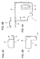
- Fig. 4A is a side view of the main body of the body-side upper bracket
- Fig. 4B is a plan view of a cut-away portion of a flange of the body-side upper bracket
- Fig. 4C is a side-view of a stand-out portion of the body-side upper bracket
- Fig. 4D is a bottom view of the stand-out portion of the body-side upper bracket.
- a steering shaft 2 is rotatably supported on the steering column 1, and a steering wheel 3 is attached to the upper end of the steering shaft 2.
- the steering column 1 is supported and secured to the car body at two portions, that is, an upper bracket in the rear part of the car and a lower bracket in the front part thereof.
- the upper bracket in the rear part of the car is comprised of a body-side upper bracket 4 (tilt bracket) secured to the car body and a column-side upper bracket 5 (distance bracket in Fig. 2) secured to the steering column 1, and the both upper brackets 4 and 5 are brought into pressure contact with each other.
- the body-side upper bracket 4 is comprised of a U-shaped main body portion 4a which is extended downward with the column 1 being located therein and flange portions 4c, 4c which are respectively extended outwardly from both side portions 4b, 4b of the main body portion 4a, and is secured to a structural member 102 of the car body at the flange portions 4c, 4c with bolts 103.
- the column-side upper bracket 5 is comprised of a column supporting portion 5a which is secured to a lower part of the column 1, both side portions which are extended downward from the column supporting portion 5a to be brought into pressure contact with the both side portions of the body-side upper bracket 4, and a bottom portion for coupling the both side portions together.
- the both side portions 4b, 4b of the body-side upper bracket 4 are respectively provided with elongated holes 6, 6 for tilt adjustment.
- the both side portions 5b, 6b of the column-side upper bracket 5 are respectively provided with circular holes 7, 7 (Fig. 2).
- a tilt caulking bolt 8 is passed through the elongated holes 6, 6 for tilt adjustment and the circular holes 7, 7.
- a tilt operation lever 9 is attached to one end of the tilt caulking bolt 8 by a caulking nut 9b through an adjustment nut 9a.
- These members constitute a tilt lock mechanism.
- elongated holes may be used instead of the circular holes 7, 7 in order to enable adjustment of a telescopic position of the steering column 1.
- substantially U-shaped coating plates 10, 10 and shock absorbing plates 11, 11 for absorbing a shock energy at the secondary collision are secured to the car body with bolts 103 at the flanges 4c, 4c of the body-side upper bracket 4.
- Each of the shock absorbing plates 11, 11 is secured to the car body by the use of the bolts 103 at the base end portion 11a thereof, and is extended to the front part of the car through the substantially U-shaped stand-out portion 4d of the body-side upper bracket 4. After being bent and folded back at an arcuate portion 11b, the shock absorbing plates 11, 11 are extended to the rear part of the car through the stand-out portion 4d.
- the coating plate 10 is disconnected due to the shock energy directed toward the front part of the car, and the body-side upper bracket 4 is moved to the front part of t he car together with the steering column 1.
- the shock absorbing plate 11 remains on the car body side since the base end portion 11a thereof is secured to the car body with the bolt 103, the arcuate portion 11b and the like are plastically deformed (drawn) inside the substantially U shaped stand-out portion 4b of the body-side upper bracket 4 which is moved to the front part of the car. It is possible to absorb the shock energy at the secondary collision due to this plastic deformation (drawing) of the shock absorbing plate 11.
- These members constitute a shock absorbing mechanism.
- the lower bracket in the front part of the car is comprised of a column-side lower bracket 12 which is secured to the steering column 1 and a body-side lower bracket 13 which is brought into pressure contact with this column-side lower bracket 12 and is secured to the car body.
- the column-side lower bracket 12 is formed with an axially elongated hole 14 which is extended in the axial direction, and a supporting pin 15 is passed through the axially elongated hole 14 of the column-side lower bracket 14 and the body-side lower bracket 12. This supporting pin 15 is caulked to be prevented to fall off.
- the steering column 1 is arranged to be telescopically adjustable, the steering column is guided along this elongated hole 14.
- the body-side upper bracket 4 is constituted in advance by a plurality of divided components, including a main body component 4a and a stand-out portion 4d which is separately formed from the main body component as a different component. Upon assembling, these plurality of divided components (the main body 4a and the stand-out portion 4d) are connected together by caulking to constitute the body-side upper bracket 4.
- the main body component 4a of the body-side upper bracket 4 integrally comprises both side portions 4b, 4b between which the steering column 1 is extended, a U-shaped portion integrally formed with a connection part for connecting the both side portions together, and flange portions 4c, 4c extending from the U-shaped portion toward the column side to be mounted on the car body.
- the flange portions 4c, 4c are provided with recesses 21, 21 in the front part of the car for caulking.
- the stand-out portion 4d as the separate component is integrally comprised of a side plate portion 4e which is disposed in parallel to the side portion 4b, in a state of being assembled in the main body component 4a as described later, and a bottom plate portion 4f which is extended between the side plate portion 4e and the side portion 4b.
- a projection 22 for caulking is formed in an upper part of the side plate portion 4e to be fitted in the caulking recesses 21, 21 of the flange portions 4c, 4c.
- the main body component 4a is formed with an insertion hole 23, and an insertion projection 24 is formed on the bottom plate portion 4f of the stand-out portion 4d to be corresponding thereto.
- the projection 22 for caulking of the stand-out portion 4d is brought into engagement with the caulking recess 21 while the insertion projection 24 with insertion hole 23 so that the main body component and the separate component are caulked and connected together, thereby constituting the body-side upper bracket 4.
- the body-side upper bracket 4 is not formed by bending one metallic plate, but by preparing in advance several divided components (the main body 4a and the stand-out portion 4d), and connecting these divided components to each other by caulking by the use of engagement portions which have been respectively processed.
- the processing can be easily performed, the number of bending operations and that of the processing steps can be reduced, and resultantly, the manufacturing cost can be reduced.
- the upper bracket 4 is formed by the several divided components (main body 4a and the stand-out portion 4d), an area of each blank can be small, so that an waste fractional material can be reduced as small as possible.
- the caulking step is employed, no gas is produced during welding, so that there arises no adverse influence on the environment and deformation due to the heat generated in welding and other bad effect are not generated. As a result, the apparatus can be stably manufactured.
- the welding step it is required to manage welding conditions or to perform inspection for confirming the conditions.
- the caulking step it can be clearly judged whether the components have been caulked or not. As a result, a problem of non-connection which can not be judged apparently can be avoided.
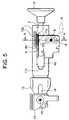
- Fig. 5 is a side view of a shock absorbing steering apparatus of a tilt telescopic type according to a second embodiment of the present invention.
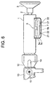
- Fig. 6 is a side view showing a state in which the body-side upper bracket (tilt bracket) is removed from the steering column apparatus in Fig. 5.
- Fig. 7 is a cross-sectional view taken along the line A-A in Fig. 5.
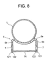
- Fig. 8 is a cross-sectional view showing a state in which only the steering column and the column-side upper bracket (distance bracket) are taken out of the steering apparatus in Fig. 7.
- Fig. 9A is a side view of the column-side upper bracket
- Fig. 9B is a plan view of a flange of the column-side upper bracket
- Fig. 9C is a bottom view of the column-side upper bracket.
- Fig. 10A is a partially enlarged side view of the column-side upper bracket
- Fig. 10B is a partially enlarged bottom view of the column-side upper bracket.
- the steering shaft 2 is supported to be rotatable by the steering column 1, and the steering wheel 3 is attached to an upper end of the steering shaft 2.
- the steering column 1 is supported and secured to the car body at two portions, that is, the upper bracket in the rear part of the car and the lower bracket in the front part thereof.
- the upper bracket in the rear part of the car is comprised of the body-side upper bracket 4 (tilt bracket) secured to the car body and the column-side upper bracket 5 (distance bracket in Fig. 6) secured to the steering column 1, and the both upper brackets 4 and 5 are brought into pressure contact with each other.
- the body-side upper bracket 4 is comprised of a U-shaped body portion 4a which is extended downward with a column 1 being located therein and flange portions 4c, 4c which are extended outwardly from the side plate portions 4b, 4b, and is secured to a structural member 102 of the car body at the flange portions 4c, 4c with bolts 103.
- the column-side upper bracket 5 is comprised of a column supporting portion 5a which is in direct contact with a lower part of the column 1 and is secured to this lower part, both side plate portions 5b, 5b which are extended downward from the column supporting portion 5a to be brought into pressure contact with the inner surfaces of the both side plate portions 4b, 4b of the body-side upper bracket 4, and a bottom portion 5c for coupling the both side plate portions together.
- the both side plate portions 4b, 4b of the body-side upper bracket 4 are respectively formed with elongated holes 6, 6 for tilting adjustment.
- the both side plate portions 5b, 5b of the column-side upper bracket 5 are formed with elongated holes 7, 7 for telescopic adjustment (Fig. 6).
- a tilt caulking bolt 8 is passed through the elongated holes 6, 6 for tilt adjustment and the elongated holes 7, 7 for telescopic adjustment, and a tilt operation lever 9 is attached to one end of the tilt caulking bolt 8 by a caulking nut 9a through an adjustment nut 9b.
- substantially U-shaped coating plates 10, 10 and shock absorbing plates 11, 11 for absorbing a shock energy at a secondary collision are secured to the car body 102 with bolts 103 at the flanges 4c, 4c of the body-side upper bracket 4.
- Each of the shock absorbing plates 11, 11 are secured to the car body by the use of the bolts 103 at the base end portions 11a, 11a thereof, and are extended to the front part of the car through the substantially U-shaped stand-out portion 4d of the body-side upper bracket 4. After being bent at an arcuate portion 11b, the shock absorbing plates 11, 11 are extended to the front part of the car through the stand-out portion 4d.
- the coating plates 10, 10 are disconnected due to the shock energy which is directed toward the front part of the car, and the body-side upper bracket 4 is moved to the front part of the car, together with the steering column 1.
- the shock absorbing plates 11, 11 remain on the car body side since the base end portions 11a, 11a thereof are secured to the car body with the bolts 103, the arcuate portion 11b and the like are plastically deformed (drawn) inside the stand-out portion 4b in the substantially U shape of the body-side upper bracket 4 which is moved to the front part of the car.
- the shock energy at the secondary collision can be absorbed by this plastic deformation (drawing) of the shock absorbing plates 11, 11.
- the lower bracket in the front part of the car is comprised of a column-side lower bracket 12 which is secured to the steering column 1 and a body-side lower bracket 13 which is brought into pressure contact with this column-side lower bracket 12 and is secured to the car body.
- the column-side lower bracket 12 is formed with an axially elongated hole 14 which is extended in the axial direction, and a supporting pin 15 is passed through the axially elongated hole 14 of the column-side lower bracket 12 and the body-side lower bracket 12. This supporting pin 15 is secured by caulking.
- the column-side upper bracket 5 is constituted by a plurality of divided components (including a main body portion 5a having a substantially M-shaped cross section for constituting a column supporting portion and a fit plate portion 5c for constituting the bottom portion). At assembling, these plurality of divided components (the main body portion 5a having a substantially M-shaped cross section and the fit plate portion 5c) are connected together by caulking to constitute the column-side upper bracket 5.
- the column-side upper bracket 5 is comprised of the main body portion and the fit plate portion 5c which is formed separately from the main body portion.
- This main body portion comprises a column supporting portion 5a which is in direct contact with a lower part of the column 1 and is secured to this lower part, and both side plate portions 5b, 5b which are extended downward integrally with the column supporting portion 5a to be brought into pressure contact with the inner surfaces of the both side plate portions 4b, 4b of the body-side upper bracket 4.
- the bottom portion of the column-side upper bracket 5 is formed as the fit plate portion 5c which is separately formed from the main body portion.
- the lower ends of the both side plate portions 5b, 5b of the main body are provided with caulking recesses 121, 121, while the both ends of the fit plate 5c are provided with projections 122 for caulking.
- the number of the caulking portions is not limited to this, but may be increased or decreased if necessary. For example, if an amount of the telescopic adjustment is great, the column-side upper bracket 5 (distance bracket) is inevitably long, so that the number of the caulking portions 121, 122 thereof becomes accordingly great.
- the caulking recesses 121 which are provided at the lower ends of the side plate portions 5b, 5b of the main body 5a are formed with cut-away portions each of which is in a reverse trapezoidal shape, so that the main body is not disconnected when the projection 122 of the fit plate 5c is caulked in. Further, there are provided spaces such as H and J so as to generate no problem even if the fit plate 5c is protruded after the caulking step. Still further, a space I is provided to make the disconnection more difficult.
- a cross section of the column-side upper bracket 5 (distance bracket) is indented only by the depth of a space L.
- a space K is set in such a manner that the tip end of the caulking projection 122 of the fit plate 5c is not projected from a frictional surface of the side plate portion 5b when being caulked.
- the caulking projection 122 is formed to have a wider upper end so as not to drawn out after being caulked.
- the column-side bracket 5 is constituted by a plurality of divided components (including a main body 5a having a substantially M-shaped cross section and a fit plate portion 5c). At assembling, these plurality of divided components (the main body 5a having a substantially M-shaped cross section and the fit plate 5c) are connected together by caulking to constitute the column-side bracket 5.
- the column-side bracket 5 is not formed by bending one metallic plate, but by preparing in advance the two divided components (the main body 5a having a substantially M-shaped cross section and the fit plate 5c), and connecting these divided components (the main body 5a having a substantially M-shaped cross section and the fit plate 5c) to each other by caulking in engagement portions which have been respectively processed.
- the processing can be easily performed, the number of bending operations and that of the processing steps can be reduced, and resultantly, the manufacturing cost can be reduced.
- the two plates (the main body 5a having a substantially M-shaped cross section and the fit plate 5c) are used, when a contact pressure is applied from the clamp mechanism onto the outer surfaces (frictional surfaces) of the both side plate portions 5b of the main body of the column-side bracket 5, as shown in Fig. 8, they can be hardly flexible and the bending rigidity or retaining capacity can be made comparatively high.
- bracket 5 is formed of the several divided components, an area of a blank can be small, so that an waste fractional material can be reduced to the minimum.
- the column-side bracket 5 can be manufactured stably.
- the welding step it is required to manage welding conditions or to perform inspection for confirming the conditions.
- the caulking step it can be clearly judged whether the components have been caulked or not. As a result, a problem of non-connection which can not be judged apparently can be avoided.
- the body-side upper bracket or the column-side bracket is constituted by a plurality of divided components, and upon assembling, these plurality of divided components are connected together by caulking to constitute the body-side upper bracket or the column-side bracket.
- the body-side upper bracket or the column-side bracket is not formed by bending one metallic plate, but by preparing in advance the several divided components, and connecting these divided components to each other by caulking in engagement portions which have been respectively processed.
- the processing can be easily performed, the number of bending operations and that of the processing steps can be reduced, and resultantly, the manufacturing cost can be reduced.
- the body-side upper bracket or the column-side bracket is formed of the several divided components, an area of a blank can be small, so that an waste fractional material can be reduced to the minimum.
- the body-side upper bracket or the column-side bracket can be manufactured stably.
- the welding step it is required to manage welding conditions or to perform inspection for confirming the conditions.
- the caulking step it can be clearly judged whether the components have been caulked or not. As a result, a problem of non-connection which can not be judged apparently can be avoided.
Landscapes
- Engineering & Computer Science (AREA)
- Chemical & Material Sciences (AREA)
- Combustion & Propulsion (AREA)
- Transportation (AREA)
- Mechanical Engineering (AREA)
- Steering Controls (AREA)
Abstract
Description
Claims (4)
- A manufacturing method of a steering column for a car in which a steering column is supported and secured on the car body through a bracket, comprising the steps of:forming in advance said bracket of a plurality of divided components, and connecting these plurality of divided components by caulking at the time of assembling, so as to assemble said bracket.
- A manufacturing method of a steering column according to Claim 1, wherein:said divided components include a main body component which integrally comprises two side portions between which the steering column passes and which extend in parallel to the axis of the steering column, a connection portion connecting said side portions to each other and two flange portions extending outwardly from the upper ends of the side portions, and a separate component which, if integrally formed with said main body component, would have complicatedly developed form and assembling step and have a form protruding from said side portions;said flange portions of said main body component and said divided components are provided with engagement portions to be engaged with each other;and said engagement portions are caulked and secured to constitute said bracket.
- A manufacturing method of a steering column apparatus for a car in which a column-side bracket attached to a steering column is brought into pressure contact with a body-side bracket attached onto the body of the car to be retained,
characterized in that:said column-side bracket is comprised of divided components including a main body portion which consists of a column supporting portion directly in contact with a lower part of the steering column and secured to said lower part and two side plate portions integrally formed with said column supporting portion and in pressure contact with the inner surfaces of the both side plate portions of said body-side bracket, and a fit plate portion which is formed separately from said main body portion for coupling said side plate portions of said main body portion to each other; andthe main body portion and the fit plate portion are connected to each other by caulking at the time of assembling, thereby assembling the column-side bracket. - A steering column apparatus for a car comprising a body-side bracket attached to the body of the car for retaining a column-side bracket attached to the steering column by bringing the column-side bracket into pressure contact with two side plate portions extending in parallel to the axis of the steering column with the steering column passing therebetween, characterized in that:said column-side bracket is comprised of a main body portion which consists of a column supporting portion directly in contact with a lower part of the steering column and secured to said lower part and two side plate portions integrally formed with said column supporting portion and in pressure contact with the inner surfaces of the both side plate portions of body-side bracket, and a fit plate portion which is formed separately from said main body portion for coupling said side plate portions of said main body portion to each other; andthe main body portion and the fit plate portion are connected to each other by caulking.
Applications Claiming Priority (5)
| Application Number | Priority Date | Filing Date | Title |
|---|---|---|---|
| JP2002138807 | 2002-05-14 | ||
| JP2002138807A JP4182684B2 (en) | 2002-05-14 | 2002-05-14 | Method and apparatus for manufacturing vehicle steering column device |
| JP2002143412A JP2003335243A (en) | 2002-05-17 | 2002-05-17 | Vehicle steering column device and method of manufacturing the same |
| JP2002143412 | 2002-05-17 | ||
| PCT/JP2003/005942 WO2003095285A1 (en) | 2002-05-14 | 2003-05-13 | Steering column device for vehicle and method of manufacturing the device |
Publications (2)
| Publication Number | Publication Date |
|---|---|
| EP1506903A1 true EP1506903A1 (en) | 2005-02-16 |
| EP1506903A4 EP1506903A4 (en) | 2006-06-28 |
Family
ID=29422415
Family Applications (1)
| Application Number | Title | Priority Date | Filing Date |
|---|---|---|---|
| EP03721102A Withdrawn EP1506903A4 (en) | 2002-05-14 | 2003-05-13 | Steering column device for vehicle and method of manufacturing the device |
Country Status (5)
| Country | Link |
|---|---|
| US (1) | US7322610B2 (en) |
| EP (1) | EP1506903A4 (en) |
| CN (1) | CN100361852C (en) |
| AU (1) | AU2003235238A1 (en) |
| WO (1) | WO2003095285A1 (en) |
Families Citing this family (5)
| Publication number | Priority date | Publication date | Assignee | Title |
|---|---|---|---|---|
| CN100369780C (en) * | 2002-07-02 | 2008-02-20 | 日本精工株式会社 | Shock-absorbing steering column device for motor vehicles |
| DE102010020633A1 (en) * | 2010-05-14 | 2011-11-17 | Gm Global Technology Operations Llc (N.D.Ges.D. Staates Delaware) | Steering column for a motor vehicle |
| US8899622B2 (en) | 2012-03-09 | 2014-12-02 | Nsk Americas, Inc. | Internally collapsible steering column assembly |
| EP3052370B1 (en) | 2013-10-04 | 2017-06-14 | NSK Americas, Inc. | Collapsible steering column assembly |
| WO2018064088A1 (en) | 2016-09-27 | 2018-04-05 | Nsk Americas, Inc. | Energy absorbing device for internally collapsing steering column assembly |
Family Cites Families (11)
| Publication number | Priority date | Publication date | Assignee | Title |
|---|---|---|---|---|
| JPS5758557A (en) * | 1980-09-26 | 1982-04-08 | Nissan Motor Co Ltd | Locking mechanism for tilting steering column |
| GB2268125A (en) * | 1992-06-19 | 1994-01-05 | Torrington Co | Energy absorbing steering column arrangement. |
| JP2928715B2 (en) | 1993-12-24 | 1999-08-03 | 株式会社山田製作所 | Support device for tilt steering shaft |
| JP3060847B2 (en) | 1994-08-30 | 2000-07-10 | トヨタ自動車株式会社 | Vehicle steering system |
| DE59705444D1 (en) * | 1996-06-27 | 2002-01-03 | Styner & Bienz Ag | Storage box for a steering shaft of a vehicle and method for producing the same |
| DE19962494A1 (en) | 1998-12-25 | 2000-07-06 | Nsk Ltd | Automatic steering column adjusting device has steering shaft position detectors and electrical shaft angle and telescopic length actuators |
| JP2001058573A (en) | 1999-08-20 | 2001-03-06 | Nsk Ltd | Steering column support device |
| JP3613702B2 (en) * | 1999-09-21 | 2005-01-26 | トヨタ自動車株式会社 | STRUCTURAL MEMBER HAVING CLOSED SECTION, ITS MANUFACTURING DEVICE, AND ITS MANUFACTURING METHOD |
| JP3468742B2 (en) | 2000-08-18 | 2003-11-17 | 株式会社山田製作所 | Rotation support structure of tilt steering |
| JP2002308111A (en) | 2001-04-16 | 2002-10-23 | Koyo Seiko Co Ltd | Steering device |
| JP2004067034A (en) * | 2002-08-09 | 2004-03-04 | Fuji Kiko Co Ltd | Steering column |
-
2003
- 2003-05-13 AU AU2003235238A patent/AU2003235238A1/en not_active Abandoned
- 2003-05-13 CN CNB038109921A patent/CN100361852C/en not_active Expired - Fee Related
- 2003-05-13 EP EP03721102A patent/EP1506903A4/en not_active Withdrawn
- 2003-05-13 US US10/511,543 patent/US7322610B2/en not_active Expired - Fee Related
- 2003-05-13 WO PCT/JP2003/005942 patent/WO2003095285A1/en not_active Ceased
Also Published As
| Publication number | Publication date |
|---|---|
| US20050173913A1 (en) | 2005-08-11 |
| EP1506903A4 (en) | 2006-06-28 |
| CN1652958A (en) | 2005-08-10 |
| WO2003095285A1 (en) | 2003-11-20 |
| US7322610B2 (en) | 2008-01-29 |
| CN100361852C (en) | 2008-01-16 |
| AU2003235238A1 (en) | 2003-11-11 |
Similar Documents
| Publication | Publication Date | Title |
|---|---|---|
| JP3681945B2 (en) | Bumper reinforcement with shock absorbing mechanism | |
| GB2365826A (en) | Collapsible tilting steering column | |
| JPH0728048Y2 (en) | Shock absorption type steering column device | |
| JP3927845B2 (en) | Bumper support structure for vehicles | |
| US7322610B2 (en) | Steering column device for vehicle and method of manufacturing the device | |
| JP2000006821A (en) | Shock absorbing steering column device | |
| JP3409572B2 (en) | Shock absorbing steering column device | |
| JP2513633Y2 (en) | Shock absorption type steering column device | |
| JP3389767B2 (en) | Shock absorbing steering column device | |
| JP4207799B2 (en) | Shock absorbing steering column device | |
| JPH08295251A (en) | Shock absorption type steering column device | |
| CN120191440A (en) | Vehicle body structure and method for manufacturing vehicle body | |
| US7472948B2 (en) | Vehicle body structure | |
| EP1600355B1 (en) | Collapsible steering apparatus | |
| JP4182684B2 (en) | Method and apparatus for manufacturing vehicle steering column device | |
| JP2007230561A (en) | Shock absorbing steering column device | |
| JP2011131704A (en) | Mounting structure of instrument panel | |
| JP4000459B2 (en) | Shock absorbing steering column device | |
| JP2587294Y2 (en) | Energy absorbing steering system | |
| JP2001114113A (en) | Energy absorbing member for shock absorbing steering system | |
| JP2005335668A (en) | Cooling system support structure for vehicles | |
| JP7842589B2 (en) | Support bracket for steering system and steering system | |
| JP2018062213A (en) | Steering device | |
| JP2025179942A (en) | Body frame structure | |
| JP6596926B2 (en) | Contact plate, contact plate mounting method, and airbag device |
Legal Events
| Date | Code | Title | Description |
|---|---|---|---|
| PUAI | Public reference made under article 153(3) epc to a published international application that has entered the european phase |
Free format text: ORIGINAL CODE: 0009012 |
|
| 17P | Request for examination filed |
Effective date: 20041208 |
|
| AK | Designated contracting states |
Kind code of ref document: A1 Designated state(s): AT BE BG CH CY CZ DE DK EE ES FI FR GB GR HU IE IT LI LU MC NL PT RO SE SI SK TR |
|
| AX | Request for extension of the european patent |
Extension state: AL LT LV MK |
|
| DAX | Request for extension of the european patent (deleted) | ||
| RBV | Designated contracting states (corrected) |
Designated state(s): DE FR GB |
|
| A4 | Supplementary search report drawn up and despatched |
Effective date: 20060531 |
|
| 17Q | First examination report despatched |
Effective date: 20070712 |
|
| STAA | Information on the status of an ep patent application or granted ep patent |
Free format text: STATUS: THE APPLICATION IS DEEMED TO BE WITHDRAWN |
|
| 18D | Application deemed to be withdrawn |
Effective date: 20100601 |