EP1506104B1 - Leuchteinheit, insbesondere als zusatzleuchte in aussenr ckb lickspiegeln von kraftfahrzeugen - Google Patents
Leuchteinheit, insbesondere als zusatzleuchte in aussenr ckb lickspiegeln von kraftfahrzeugen Download PDFInfo
- Publication number
- EP1506104B1 EP1506104B1 EP03714636A EP03714636A EP1506104B1 EP 1506104 B1 EP1506104 B1 EP 1506104B1 EP 03714636 A EP03714636 A EP 03714636A EP 03714636 A EP03714636 A EP 03714636A EP 1506104 B1 EP1506104 B1 EP 1506104B1
- Authority
- EP
- European Patent Office
- Prior art keywords
- led
- reflector
- lighting unit
- reflective surface
- rays
- Prior art date
- Legal status (The legal status is an assumption and is not a legal conclusion. Google has not performed a legal analysis and makes no representation as to the accuracy of the status listed.)
- Expired - Lifetime
Links
- 239000000463 material Substances 0.000 claims description 3
- 239000011248 coating agent Substances 0.000 claims description 2
- 238000000576 coating method Methods 0.000 claims description 2
- 230000002093 peripheral effect Effects 0.000 claims 2
- 239000004020 conductor Substances 0.000 abstract description 4
- 238000005516 engineering process Methods 0.000 abstract description 2
- 238000005286 illumination Methods 0.000 abstract 1
- 239000002184 metal Substances 0.000 abstract 1
- 230000005855 radiation Effects 0.000 description 5
- 239000000969 carrier Substances 0.000 description 2
- 239000011888 foil Substances 0.000 description 2
- 238000005476 soldering Methods 0.000 description 2
- 230000001154 acute effect Effects 0.000 description 1
- 230000015572 biosynthetic process Effects 0.000 description 1
- 238000000034 method Methods 0.000 description 1
Images


Classifications
-
- B—PERFORMING OPERATIONS; TRANSPORTING
- B60—VEHICLES IN GENERAL
- B60Q—ARRANGEMENT OF SIGNALLING OR LIGHTING DEVICES, THE MOUNTING OR SUPPORTING THEREOF OR CIRCUITS THEREFOR, FOR VEHICLES IN GENERAL
- B60Q1/00—Arrangement of optical signalling or lighting devices, the mounting or supporting thereof or circuits therefor
- B60Q1/26—Arrangement of optical signalling or lighting devices, the mounting or supporting thereof or circuits therefor the devices being primarily intended to indicate the vehicle, or parts thereof, or to give signals, to other traffic
-
- B—PERFORMING OPERATIONS; TRANSPORTING
- B60—VEHICLES IN GENERAL
- B60Q—ARRANGEMENT OF SIGNALLING OR LIGHTING DEVICES, THE MOUNTING OR SUPPORTING THEREOF OR CIRCUITS THEREFOR, FOR VEHICLES IN GENERAL
- B60Q1/00—Arrangement of optical signalling or lighting devices, the mounting or supporting thereof or circuits therefor
- B60Q1/26—Arrangement of optical signalling or lighting devices, the mounting or supporting thereof or circuits therefor the devices being primarily intended to indicate the vehicle, or parts thereof, or to give signals, to other traffic
- B60Q1/2661—Arrangement of optical signalling or lighting devices, the mounting or supporting thereof or circuits therefor the devices being primarily intended to indicate the vehicle, or parts thereof, or to give signals, to other traffic mounted on parts having other functions
- B60Q1/2665—Arrangement of optical signalling or lighting devices, the mounting or supporting thereof or circuits therefor the devices being primarily intended to indicate the vehicle, or parts thereof, or to give signals, to other traffic mounted on parts having other functions on rear-view mirrors
-
- B—PERFORMING OPERATIONS; TRANSPORTING
- B60—VEHICLES IN GENERAL
- B60R—VEHICLES, VEHICLE FITTINGS, OR VEHICLE PARTS, NOT OTHERWISE PROVIDED FOR
- B60R1/00—Optical viewing arrangements; Real-time viewing arrangements for drivers or passengers using optical image capturing systems, e.g. cameras or video systems specially adapted for use in or on vehicles
- B60R1/12—Mirror assemblies combined with other articles, e.g. clocks
- B60R1/1207—Mirror assemblies combined with other articles, e.g. clocks with lamps; with turn indicators
-
- F—MECHANICAL ENGINEERING; LIGHTING; HEATING; WEAPONS; BLASTING
- F21—LIGHTING
- F21S—NON-PORTABLE LIGHTING DEVICES; SYSTEMS THEREOF; VEHICLE LIGHTING DEVICES SPECIALLY ADAPTED FOR VEHICLE EXTERIORS
- F21S43/00—Signalling devices specially adapted for vehicle exteriors, e.g. brake lamps, direction indicator lights or reversing lights
- F21S43/30—Signalling devices specially adapted for vehicle exteriors, e.g. brake lamps, direction indicator lights or reversing lights characterised by reflectors
- F21S43/31—Optical layout thereof
- F21S43/315—Optical layout thereof using total internal reflection
-
- F—MECHANICAL ENGINEERING; LIGHTING; HEATING; WEAPONS; BLASTING
- F21—LIGHTING
- F21V—FUNCTIONAL FEATURES OR DETAILS OF LIGHTING DEVICES OR SYSTEMS THEREOF; STRUCTURAL COMBINATIONS OF LIGHTING DEVICES WITH OTHER ARTICLES, NOT OTHERWISE PROVIDED FOR
- F21V7/00—Reflectors for light sources
- F21V7/0008—Reflectors for light sources providing for indirect lighting
-
- F—MECHANICAL ENGINEERING; LIGHTING; HEATING; WEAPONS; BLASTING
- F21—LIGHTING
- F21V—FUNCTIONAL FEATURES OR DETAILS OF LIGHTING DEVICES OR SYSTEMS THEREOF; STRUCTURAL COMBINATIONS OF LIGHTING DEVICES WITH OTHER ARTICLES, NOT OTHERWISE PROVIDED FOR
- F21V7/00—Reflectors for light sources
- F21V7/0091—Reflectors for light sources using total internal reflection
-
- F—MECHANICAL ENGINEERING; LIGHTING; HEATING; WEAPONS; BLASTING
- F21—LIGHTING
- F21S—NON-PORTABLE LIGHTING DEVICES; SYSTEMS THEREOF; VEHICLE LIGHTING DEVICES SPECIALLY ADAPTED FOR VEHICLE EXTERIORS
- F21S43/00—Signalling devices specially adapted for vehicle exteriors, e.g. brake lamps, direction indicator lights or reversing lights
- F21S43/10—Signalling devices specially adapted for vehicle exteriors, e.g. brake lamps, direction indicator lights or reversing lights characterised by the light source
- F21S43/13—Signalling devices specially adapted for vehicle exteriors, e.g. brake lamps, direction indicator lights or reversing lights characterised by the light source characterised by the type of light source
- F21S43/14—Light emitting diodes [LED]
-
- F—MECHANICAL ENGINEERING; LIGHTING; HEATING; WEAPONS; BLASTING
- F21—LIGHTING
- F21Y—INDEXING SCHEME ASSOCIATED WITH SUBCLASSES F21K, F21L, F21S and F21V, RELATING TO THE FORM OR THE KIND OF THE LIGHT SOURCES OR OF THE COLOUR OF THE LIGHT EMITTED
- F21Y2115/00—Light-generating elements of semiconductor light sources
- F21Y2115/10—Light-emitting diodes [LED]
Definitions
- the invention relates to a lighting unit, in particular as a supplementary light in exterior rearview mirrors of motor vehicles, according to the preamble of claim 1.
- LEDs are provided for the lateral emission of light. These LEDs are mounted on separate sheet carriers, so-called clinching plates, conductor foils or printed circuit boards. The use of such carriers and the mounting of the LEDs on them is relatively expensive and expensive.
- the DE 297 08 858 U1 is a light source with a lens arranged in the beam path known.
- the lens In the region of a front side lying in the beam path, the lens has a totally reflecting surface on which the rays are at least partly reflected to the side as a result of total reflection.
- the lens is part of a cap turned over over the illuminant.
- the totally reflecting surface is conical, with the cone tip facing the light source.
- a lighting unit in particular known as auxiliary indicator in exterior rear-view mirrors of motor vehicles, with at least one LED and at least one reflector which reflects the rays coming from the LED in the direction of a lens.
- a reflector element Arranged in the beam path of the rays emanating from the LED is a reflector element with a totally reflecting surface facing the LED, which reflects at least part of the rays emitted by the LED forward in the direction of the lens to the reflector.
- the Reflector elements are individually attached to the respective associated reflector or formed integrally with the reflector, or that the reflector elements are formed directly on the lens, or that the reflector elements are interconnected by a strip-shaped carrier, or are integrally formed with a plurality of reflector elements connecting carrier.
- each LED can be frontward equipped with a converging lens or with a scattering lens, which is mirrored or at least partially mirrored and radiation either bundled in the frontal direction, or reflected laterally in the direction of an optional reflector.
- the LED may have a mirrored or non-mirrored frontward concave curvature, which radiates a larger part of the radiation onto the optional reflector.
- An optionally formed as a reflector support plate on which the LEDs are arranged, may be covered by a collection or scattering lens.
- Each LED has its own reflector or is arranged in a reflector directing the radiation onto a target.
- a lighting unit with a plurality of LEDs is known, some of which are arranged inclined in a portion relative to a main emission of the light unit. At least a portion of the LEDs each have a LED associated with a deflecting element by which at least a part of the light emitted by the respective LED is deflected in such a way that it can be used for the light emission of the lighting unit in the main radiation direction.
- the invention has the object of providing a light unit of this type so that the light source can be arranged for lateral radiation in a simple cost-effective manner while avoiding additional carrier.
- the light source Since the light source is provided with the totally reflecting surface, the light does not reach the outside in this area.
- the light source must therefore only be installed so that the light emerges in the desired direction, especially in the lateral direction. At the reflector, the rays are then reflected to the lens.
- the luminous means can be arranged such that, depending on the insert part of the lighting unit according to the invention, the light falls in the desired direction.
- the light source does not have to be installed at an angle so that additional sheets, conductor foils or printed circuit boards are no longer possible required are. As a result, the light unit can be produced easily and inexpensively.
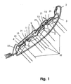
- Fig. 1 shows a lighting unit with a housing 1, the housing opening is covered with a lens 2.
- a reflector 2 spaced apart from the lens 2 is provided, the inside of which is provided with individual reflector surfaces 5, 6, on which rays S of lamps 10 to 13 are reflected toward the lens 2.
- a printed circuit board 8 Between the rear wall 7 and the reflector 3 is a printed circuit board 8, which carries the bulbs 10 to 13 and other electronic components, such as resistors 9.
- the lamps 10 to 13 are LEDs that are soldered, welded or otherwise attached to the printed circuit board 8 on it.
- the lighting unit has a plurality of spaced apart one behind the other bulbs 10 to 13. Depending on the design of the lighting unit, the lighting means can also be provided in a different arrangement.
- the LED 10 has feet 4 which protrude through openings 20 in the printed circuit board 8 and are advantageously connected by soldering to (not shown) printed conductors.
- the reflector 3 is provided with a passage opening 21 through which the LED 10 projects. It has a longitudinal side convexly curved outward end face 14, at which the rays of the LED 10 in the direction of this end face 14 going to be totally reflected.
- the end face 14 may be mirrored on the inside for this purpose.
- Fig. 2 shows the end face 14 connects at the axial outer end at an acute angle and at the axially inner end obtusely to the lateral surface 16, which may lie on the jacket of a cylinder.
- the LED 10, viewed in the axial direction on the front side 14, has a circular outline.
- the end face 14 extends from the free end 15 of the LED 10 over more than half their height.
- the reflected rays at the end face 14 S1 are deflected in the opposite direction so that they pass through the lateral surface 16 and meet the obliquely extending to her reflector surfaces 6. They are located on partial rings which are coaxial with the central axis of the reflector 3.
- the reflector surface 5, 6 having part 22 of the reflector 3 is approximately parabolic.
- the reflector surfaces 6 are formed so that the rays S1 are reflected approximately parallel to each other to the lens 2.
- the reflected rays S2 strike the lens 2 approximately perpendicularly (FIG. Fig. 1 ).
- the front side 14 of the LED 10 may be provided on the inside with a coating or the like to achieve a total reflection.
- the front page 14 can also be made of a totally reflective Material exist while the lateral surface 16 is made of translucent material.
- the reflector 3 consists of two identical reflector parts 22, which are advantageously integrally formed with each other.
- Each reflector member 22 has two spaced adjacent passage openings 21, through which in each case an LED 10, 11 and 12, 13 protrudes.
- the two LEDs 10, 11 and 12, 13 arranged so mirror images of each other that the totally reflective end faces 14 face each other.
- the LEDs 10 and 11 or 12 and 13 emit light in the opposite direction.
- the rays emanating from the LEDs 10 and 12 strike the reflector surface 6 and the rays emitted by the LEDs 11 and 13 impinge on the reflector surfaces 5 inclined in opposite directions.
- the LEDs 10 to 13 need not be arranged obliquely for the lateral emission of the light.
- An additional printed circuit board, an additional sheet and the like for the LEDs 10 to 13 can be saved.
- the LEDs 10 to 13 can be mounted in a conventional soldering process on the printed circuit board 8, so that the lighting unit can be easily and inexpensively manufactured.
- the LED 10a may also be formed so that the totally reflective end face 14a is flat and is at an angle to the longitudinal axis of the LED 10a.
- the beams S are reflected parallel to each other at the end face 14a.
- the reflected rays are reflected at the reflector surfaces 6a to the lens 2.
- LED 10b has the inclined end face 14b according to the embodiment Fig. 3 ,
- the lateral surface 15b is in the area in which the at the end face 14b total reflected rays S out of the LED outward, provided with a refractive optics.
- the rays S are diffracted so that they fall on the reflector surfaces 6b.
- the reflector surfaces 5b lie in the shadow of the rays S.
- the rays S2 reflected at the reflector surfaces 6b strike the lens 2, through which they emerge from the light unit.
- the rays S emerge from the LED 10b at different angles and are reflected parallel to each other at the reflector surfaces 6b. It is also possible to make the arrangement so that the rays S are easily scattered.
- the LEDs according to the Fig. 1 to 4 can be mixed in the lighting unit. It is also possible, the refractive optics 18 in the LED 10 according to Fig. 1 and 2 provided.
- the lighting unit can be optimally adapted in this way to the application.
- the light unit is advantageously used as an additional light in exterior rearview mirrors of motor vehicles. However, it can of course be used in all fields of signal or lighting technology.
Landscapes
- Engineering & Computer Science (AREA)
- General Engineering & Computer Science (AREA)
- Mechanical Engineering (AREA)
- Multimedia (AREA)
- Non-Portable Lighting Devices Or Systems Thereof (AREA)
- Led Device Packages (AREA)
Abstract
Description
- Die Erfindung betrifft eine Leuchteinheit, insbesondere als Zusatzleuchte in Außenrückblickspiegeln von Kraftfahrzeugen, nach dem Oberbegriff des Anspruches 1.
- Es sind Leuchteinheiten bekannt, bei denen zur seitlichen Abstrahlung des Lichts schräg angeordnete LEDs vorgesehen sind. Diese LEDs sind auf gesonderten Blechträgern, sogenannten Clinchblechen, Leiterfolien oder Leiterplatinen befestigt. Die Verwendung solcher Träger und die Befestigung der LEDs auf ihnen ist relativ aufwendig und teuer.
- Durch die
DE 297 08 858 U1 ist ein Leuchtmittel mit einer in dessen Strahlengang angeordneten Linse bekannt. Die Linse weist im Bereich einer in dem Strahlengang liegenden Frontseite eine total reflektierende Fläche auf, an der die Strahlen infolge Totalreflexion zumindest teilweise zur Seite reflektiert werden. Die Linse ist Bestandteil einer über das Leuchtmittel gestülpten Kappe. Die total reflektierende Fläche ist konisch ausgebildet, wobei die Konusspitze dem Leuchtmittel zugewandt ist. - Durch die
DE 200 13 330 U1 ist eine Leuchteinheit, insbesondere als Zusatzblinkleuchte in Außenrückspiegeln von Kraftfahrzeugen bekannt, mit mindestens einer LED und mindestens einem Reflektor, der die von der LED kommenden Strahlen in Richtung auf eine Lichtscheibe reflektiert. In dem Strahlengang der von der LED ausgehenden Strahlen ist ein Reflektorelement mit einer der LED zugewandten total reflektierenden Fläche angeordnet, welche zumindest einen Teil der von der LED nach vorn in Richtung der Lichtscheibe abgegebenen Strahlen zum Reflektor reflektiert. Dabei ist vorgesehen, dass die Reflektorelemente einzeln am jeweils zugehörigen Reflektor befestigt oder einstückig mit dem Reflektor ausgebildet sind, oder dass die Reflektorelemente direkt an der Lichtscheibe ausgebildet sind, oder dass die Reflektorelemente durch einen streifenförmigen Träger miteinander verbunden sind, oder einstückig mit einem mehrere Reflektorelemente verbindenden Träger ausgebildet sind. - Durch die
DE 199 37 852 A1 ist eine Leuchteinheit mit mehreren LEDs als Leuchtmittel bekannt. Jede LED kann frontwärtig mit einer Sammellinse oder mit einer Streulinse ausgestattet sein, welche unverspiegelt oder zumindest teilweise verspiegelt ist und Strahlung entweder in frontaler Richtung gebündelt, oder seitlich in Richtung eines gegebenenfalls vorhandenen Reflektors reflektiert. Die LED kann eine verspiegelte oder unverspiegelte frontwärtige konkave Wölbung aufweisen, welche einen größeren Teil der Strahlung auf den gegebenenfalls vorhandenen Reflektor abstrahlt. Eine gegebenenfalls als Reflektor ausgebildete Trägerplatte, auf der die LEDs angeordnet sind, kann von einer Sammel- oder Streulinse abgedeckt sein. Jede LED weist selbst einen Reflektor auf oder ist in einem die Strahlung auf ein Ziel richtenden Reflektor angeordnet. - Durch die
DE 196 46 042 A1 ist eine Leuchteinheit mit mehreren LEDs bekannt, von denen einige in einem Abschnitt geneigt gegenüber einer Hauptabstrahlrichtung der Leuchteinheit angeordnet sind. Zumindest einem Teil der LEDs ist jeweils einer LED ein Umlenkelement zugeordnet, durch das zumindest ein Teil des von der jeweiligen LED ausgesandten Lichts derart umgelenkt wird, dass es für die Lichtabgabe der Leuchteinheit in deren Hauptabstrahlrichtung nutzbar ist. - Der Erfindung liegt die Aufgabe zugrunde, eine Leuchteinheit dieser Art so auszubilden, dass das Leuchtmittel zur seitlichen Abstrahlung auf einfache kostengünstige Weise unter Vermeidung zusätzlicher Träger angeordnet werden kann.
- Diese Aufgabe wird bei einer Leuchteinheit der gattungsbildenden Art erfindungsgemäß mit den kennzeichnenden Merkmalen des unabhängigen Anspruchs 1 bzw. mit den kennzeichnenden Merkmalen des unabhängigen Anspruchs 2 gelöst.
- Da das Leuchtmittel mit der total reflektierenden Fläche versehen ist, gelangt das Licht in diesem Bereich nicht nach außen. Das Leuchtmittel muss darum nur so eingebaut werden, dass das Licht in der gewünschten Richtung austritt, insbesondere in seitlicher Richtung. Am Reflektor werden die Strahlen dann zur Lichtscheibe reflektiert. Das Leuchtmittel kann infolge der total reflektierenden Fläche so angeordnet werden, dass je nach Einsatzteil der erfindungsgemäßen Leuchteinheit das Licht in die gewünschte Richtung fällt. Das Leuchtmittel muss nicht schräg eingebaut werden, so dass zusätzliche Bleche, Leiterfolien oder-platinen nicht mehr erforderlich sind. Dadurch läßt sich die Leuchteinheit einfach und kostengünstig herstellen.
- Weitere Merkmale der Erfindung ergeben sich aus den weiteren Ansprüchen, der Beschreibung und den Zeichnungen.
- Die Erfindung wird nachstehend anhand dreier in den Zeichnungen dargestellter Ausführungsbeispiele näher beschrieben. Es zeigt:
- Fig. 1
- im Längsschnitt eine erfindungsgemäße Leuchteinheit,
- Fig. 2
- in vergrößerter Darstellung einen Teil der erfindungs- gemäßen Leuchteinheit mit einer LED,
- Fig. 3 und 4
- in Darstellungen entsprechend
Fig. 2 weitere Ausführungsformen von erfindungsgemäßen Leuchteinheiten. -
Fig. 1 zeigt eine Leuchteinheit mit einem Gehäuse 1, dessen Gehäuseöffnung mit einer Lichtscheibe 2 abgedeckt ist. Im Gehäuse 1 ist ein der Lichtscheibe 2 mit Abstand gegenüberliegender Reflektor 3 vorgesehen, dessen Innenseite mit einzelnen Reflektorflächen 5, 6 versehen ist, an denen Strahlen S von Leuchtmitteln 10 bis 13 zur Lichtscheibe 2 reflektiert werden. Zwischen der Gehäuserückwand 7 und dem Reflektor 3 liegt eine Leiterplatine 8, die die Leuchtmittel 10 bis 13 sowie weitere elektronische Bauteile, wie Widerstände 9, trägt. - Die Leuchtmittel 10 bis 13 sind LEDs, die auf die Leiterplatine 8 aufgelötet, aufgeschweißt oder auf sonstige Weise auf ihr befestigt sind. Die Leuchteinheit weist mehrere, mit Abstand hintereinander liegende Leuchtmittel 10 bis 13 auf. Je nach Ausbildung der Leuchteinheit können die Leuchtmittel auch in anderer Anordnung vorgesehen sein.
- Anhand von
Fig. 2 wird die Ausbildung und Lage eines der Leuchtmittel in bezug zum Reflektor 3 näher beschrieben. Die anderen Leuchtmittel sind in gleicher Weise ausgebildet und relativ zum Reflektor 3 angeordnet. - Die LED 10 hat Füße 4, die durch Öffnungen 20 in der Leiterplatine 8 ragen und vorteilhaft durch Löten an (nicht dargestellte) Leiterbahnen angeschlossen sind. Der Reflektor 3 ist mit einer Durchtrittsöffnung 21 versehen, durch die die LED 10 ragt. Sie hat eine im Längsschnitt konvex nach außen gewölbte Stirnseite 14, an der die von der LED 10 in Richtung auf diese Stirnseite 14 gehenden Strahlen S1 total reflektiert werden. Die Stirnseite 14 kann hierfür innenseitig verspiegelt sein. Wie
Fig. 2 zeigt, schließt die Stirnseite 14 am axial äußeren Ende spitzwinklig und am axial inneren Ende stumpfwinklig an die Mantelfläche 16 an, die auf dem Mantel eines Zylinders liegen kann. In diesem Fall hat die LED 10, in Achsrichtung auf die Stirnseite 14 gesehen, kreisförmigen Umriß. Die Stirnseite 14 erstreckt sich vom freien Ende 15 der LED 10 über mehr als deren halbe Höhe. - Die an der Stirnseite 14 reflektierten Strahlen S1 werden dabei in entgegengesetzter Richtung so abgelenkt, daß sie durch die Mantelfläche 16 hindurchtreten und auf die schräg zu ihr verlaufenden Reflektorflächen 6 treffen. Sie liegen auf Teilringen, die koaxial zur Mittelachse des Reflektors 3 liegen. Der die Reflektorfläche 5, 6 aufweisende Teil 22 des Reflektors 3 ist etwa parabelförmig ausgebildet. Die Reflektorflächen 6 sind so ausgebildet, daß die Strahlen S1 etwa parallel zueinander zur Lichtscheibe 2 reflektiert werden. Die reflektierten Strahlen S2 treffen etwa senkrecht auf die Lichtscheibe 2 (
Fig. 1 ). - Anstelle der Verspiegelung kann zur Erzielung einer Totalreflexion die Stirnseite 14 der LED 10 innenseitig mit einer Beschichtung oder dergleichen versehen sein. Die Stirnseite 14 kann aber auch aus einem total reflektierenden Material bestehen, während die Mantelfläche 16 aus lichtdurchlässigem Material besteht.
- Wie
Fig. 1 zeigt, besteht der Reflektor 3 aus zwei gleichen Reflektorteilen 22, die vorteilhaft einstückig miteinander ausgebildet sind. Jeder Reflektorteil 22 hat zwei mit Abstand nebeneinander liegende Durchtrittsöffnungen 21, durch die jeweils eine LED 10, 11 und 12, 13 ragt. Innerhalb jedes Reflektorteiles 22 sind die beiden LEDs 10, 11 und 12, 13 so spiegelbildlich zueinander angeordnet, daß die total reflektierenden Stirnseiten 14 einander zugewandt sind. Dadurch strahlen die LEDs 10 und 11 bzw. 12 und 13 in entgegengesetzter Richtung Licht ab. Die von den LEDs 10 und 12 ausgehenden Strahlen treffen auf die Reflektorfläche 6 und die von den LEDs 11 und 13 ausgesandten Strahlen auf die gegensinnig geneigten Reflektorflächen 5. - Aufgrund der beschriebenen Ausbildung müssen die LEDs 10 bis 13 für die seitliche Abstrahlung des Lichtes nicht schräg angeordnet werden. Eine zusätzliche Leiterplatine, ein Zusatzblech und dergleichen für die LEDs 10 bis 13 kann eingespart werden. Die LEDs 10 bis 13 können in einem üblichen Lötprozeß auf der Leiterplatine 8 befestigt werden, so daß die Leuchteinheit einfach und kostengünstig hergestellt werden kann.
- Wie
Fig. 3 zeigt, kann die LED 10a auch so ausgebildet sein, daß die total reflektierende Stirnseite 14a eben ausgebildet ist und winklig zur Längsachse der LED 10a liegt. In diesem Fall werden die Strahlen S im Unterschied zur vorigen Ausführungsform parallel zueinander an der Stirnseite 14a reflektiert. Die reflektierten Strahlen werden an den Reflektorflächen 6a zur Lichtscheibe 2 reflektiert. - Bei der Ausführungsform gemäß
Fig. 4 hat die LED 10b die geneigte Stirnseite 14b entsprechend dem Ausführungsbeispiel nachFig. 3 . Die Mantelfläche 15b ist in dem Bereich, in dem die an der Stirnseite 14b total reflektierten Strahlen S aus der LED nach außen treten, mit einer Brechungsoptik versehen. Beim Durchtritt durch die Brechungsoptik 18 werden die Strahlen S so gebeugt, daß sie auf die Reflektorflächen 6b fallen. Wie bei den anderen Ausführungsformen liegen die Reflektorflächen 5b im Schatten der Strahlen S. Die an den Reflektorflächen 6b reflektierten Strahlen S2 treffen auf die Lichtscheibe 2, durch welche sie aus der Leuchteinheit austreten. Die Strahlen S treten unter unterschiedlichen Winkeln aus der LED 10b aus und werden an den Reflektorflächen 6b parallel zueinander reflektiert. Es ist auch möglich, die Anordnung so zu treffen, daß die Strahlen S leicht gestreut werden. - Es ist ohne weiteres möglich, die LEDs gemäß den
Fig. 1 bis 4 gemischt in der Leuchteinheit vorzusehen. Auch ist es möglich, die Brechungsoptik 18 bei der LED 10 gemäßFig. 1 und2 vorzusehen. Die Leuchteinheit läßt sich auf diese Weise optimal an den Einsatzfall anpassen. - Die Leuchteinheit wird vorteilhaft als Zusatzleuchte in Außenrückblickspiegeln von Kraftfahrzeugen eingesetzt. Sie kann aber selbstverständlich auf allen Gebieten der Signal- bzw. Beleuchtungstechnik eingesetzt werden.
Claims (10)
- Leuchteinheit, insbesondere als Zusatzblinkleuchte in Außenrückspiegeln von Kraftfahrzeugen, mit mindestens einer LED (10, 11, 12, 13; 10a; 10b), und mindestens einem Reflektor, der die von der LED (10, 11, 12, 13; 10a; 10b) kommenden Strahlen in Richtung auf eine Lichtscheibe reflektiert, wobei die LED (10, 11, 12, 13; 10a; 10b) mindestens eine total reflektierende Fläche (14, 14a, 14b) aufweist, an der die Strahlen zum Reflektor (3) reflektiert werden,
dadurch gekennzeichnet, dass die total reflektierende Fläche (14, 14a, 14b) schräg zur Achse der LED (10, 11, 12, 13; 10a; 10b) liegt und die total reflektierende Fläche (14a; 14b) eben ausgeführt ist. - Leuchteinheit, insbesondere als Zusatzblinkleuchte in Außenrückspiegeln von Kraftfahrzeugen, mit mindestens einer LED (10, 11, 12, 13; 10a; 10b), und mindestens einem Reflektor, der die von der LED (10, 11, 12, 13; 10a; 10b) kommenden Strahlen in Richtung auf eine Lichtscheibe reflektiert, wobei die LED (10, 11, 12, 13; 10a; 10b) mindestens eine total reflektierende Fläche (14, 14a, 14b) aufweist, an der die Strahlen zum Reflektor (3) reflektiert werden,
dadurch gekennzeichnet, dass die total reflektierende Fläche (14, 14a, 14b) schräg zur Achse der LED (10, 11, 12, 13; 10a; 10b) liegt, und die total reflektierende Fläche (14) konvex nach außen gewölbt ist. - Leuchteinheit nach Anspruch 1 oder 2,
dadurch gekennzeichnet, dass die reflektierende Fläche (14; 14a; 14b) eine reflektierende Beschichtung und/oder Verspiegelung aufweist und/oder aus einem reflektierenden Material besteht. - Leuchteinheit nach Anspruch 1, 2 oder 3,
dadurch gekennzeichnet, dass sich die total reflektierende Fläche (14, 14a, 14b) über einen Teil der Höhe der LED (10, 11, 12, 13; 10a; 10b) erstreckt. - Leuchteinheit nach einem der vorhergehenden Ansprüche,
dadurch gekennzeichnet, dass die total reflektierende Fläche (14, 14a, 14b) die Strahlen quer zur Achse der LED (10, 11, 12, 13; 10a; 10b) reflektiert. - Leuchteinheit nach einem der vorhergehenden Ansprüche,
dadurch gekennzeichnet, dass die Mantelfläche (16, 16b) des Leuchtmittels (10, 11, 12, 13; 10a; 10b) im Bereich der durch sie hindurchgehenden, an der total reflektierenden Fläche (14; 14a; 14b) reflektierten Strahlen mit einer Brechungsoptik (18) versehen ist. - Leuchteinheit nach Anspruch 6,
dadurch gekennzeichnet, dass die Brechungsoptik (18) durch Linsen gebildet ist. - Leuchteinheit nach einem der vorhergehenden Ansprüche,
dadurch gekennzeichnet, dass zwei spiegelbildlich zueinander angeordnete LEDs (10, 11, 12, 13; 10a; 10b) vorgesehen sind, die Licht nach entgegengesetzten Richtungen abstrahlen. - Leuchteinheit nach einem der vorhergehenden Ansprüche,
dadurch gekennzeichnet, dass der Reflektor (3) wenigstens zwei nebeneinander liegende Reflektorteile (22) aufweist. - Leuchteinheit nach Anspruch 9,
dadurch gekennzeichnet, dass jeder Reflektorteil (22) zwei spiegelbildlich oder gleich zueinander angeordnete LEDs (10, 11, 12, 13; 10a; 10b) aufweist.
Applications Claiming Priority (3)
| Application Number | Priority Date | Filing Date | Title |
|---|---|---|---|
| DE10211189 | 2002-03-14 | ||
| DE10211189A DE10211189A1 (de) | 2002-03-14 | 2002-03-14 | Leuchteinheit, insbesondere als Zusatzeinheit in Außenrückblickspiegeln von Kraftfahrzeugen |
| PCT/DE2003/000444 WO2003078203A1 (de) | 2002-03-14 | 2003-02-14 | Leuchteinheit, insbesondere als zusatzleuchte in aussenrückblickspiegeln von kraftfahrzeugen |
Publications (2)
| Publication Number | Publication Date |
|---|---|
| EP1506104A1 EP1506104A1 (de) | 2005-02-16 |
| EP1506104B1 true EP1506104B1 (de) | 2010-09-01 |
Family
ID=27815628
Family Applications (1)
| Application Number | Title | Priority Date | Filing Date |
|---|---|---|---|
| EP03714636A Expired - Lifetime EP1506104B1 (de) | 2002-03-14 | 2003-02-14 | Leuchteinheit, insbesondere als zusatzleuchte in aussenr ckb lickspiegeln von kraftfahrzeugen |
Country Status (7)
| Country | Link |
|---|---|
| US (1) | US20050219857A1 (de) |
| EP (1) | EP1506104B1 (de) |
| JP (1) | JP2005519809A (de) |
| KR (1) | KR20040099308A (de) |
| AU (1) | AU2003218871A1 (de) |
| DE (3) | DE10211189A1 (de) |
| WO (1) | WO2003078203A1 (de) |
Families Citing this family (7)
| Publication number | Priority date | Publication date | Assignee | Title |
|---|---|---|---|---|
| ES2215486B1 (es) | 2004-03-01 | 2005-06-16 | Fico Mirrors, S.A | Conjunto de espejo retrovisor de vehiculos automovil con un dispositivo intermitente. |
| US7559635B2 (en) * | 2006-05-17 | 2009-07-14 | Lexmark International, Inc. | Apparatus for facilitating determination of proper supply cartridge installation |
| JP4631838B2 (ja) * | 2006-10-20 | 2011-02-16 | 市光工業株式会社 | 車両用灯具 |
| FR2928992B1 (fr) * | 2008-03-19 | 2010-05-14 | Cml Innovative Technologies | Systeme d'eclairage a diode electroluminescente. |
| KR101114090B1 (ko) * | 2009-06-22 | 2012-02-20 | 기아자동차주식회사 | 차량용 선형 미등 |
| US8992060B2 (en) * | 2013-05-08 | 2015-03-31 | Ford Global Technologies, Llc | Uniform illumination of lamps |
| DE102016101997A1 (de) * | 2016-02-04 | 2017-08-10 | SMR Patents S.à.r.l. | Beleuchtungseinrichtung und Rückblickeinrichtung für Fahrzeuge |
Family Cites Families (29)
| Publication number | Priority date | Publication date | Assignee | Title |
|---|---|---|---|---|
| US4947303A (en) * | 1986-05-19 | 1990-08-07 | Musco Corporation | Glare control lamp and reflector assembly and method for glare control |
| US4994947A (en) * | 1989-11-20 | 1991-02-19 | Ford Motor Company | Reflector and lighting fixture comprising same |
| US5438485A (en) * | 1993-01-07 | 1995-08-01 | Ford Motor Company | Illuminator for use with a remote light source |
| FR2707223B1 (fr) * | 1993-07-07 | 1995-09-29 | Valeo Vision | Feu de signalisation perfectionné à diodes électroluminescentes. |
| US5526237A (en) * | 1993-12-10 | 1996-06-11 | General Electric Company | Lighting system for increasing brightness to a light guide |
| US5660462A (en) * | 1994-09-13 | 1997-08-26 | Osram Sylvania Inc. | High efficiency vehicle headlights and reflector lamps |
| US5806957A (en) * | 1996-02-22 | 1998-09-15 | Siegel-Robert, Inc. | Sealed automotive emblem lighting assembly and method |
| DE19646042B4 (de) * | 1996-11-08 | 2006-11-16 | Automotive Lighting Reutlingen Gmbh | Fahrzeug-Beleuchtungseinrichtung |
| US5760531A (en) * | 1996-11-19 | 1998-06-02 | 911 Emergency Products, Inc. | Lamp having protective dome |
| DE29708858U1 (de) * | 1997-05-20 | 1997-07-31 | EBT Licht-Technik GmbH & Co. KG, 67098 Bad Dürkheim | Anzeigeelement |
| DE69919095T2 (de) * | 1998-03-26 | 2005-08-11 | Koninklijke Philips Electronics N.V. | Elektrische lampe |
| US6361190B1 (en) * | 1999-06-25 | 2002-03-26 | Mcdermott Kevin | Large surface LED lighting device |
| JP2001053341A (ja) * | 1999-08-09 | 2001-02-23 | Kazuo Kobayashi | 面発光表示器 |
| DE19937852C2 (de) * | 1999-08-13 | 2002-05-29 | Thomas Strobl | Tragbare Leuchte und deren Verwendung |
| DE60040453D1 (de) * | 2000-01-21 | 2008-11-20 | Stanley Electric Co Ltd | Signalleuchte für Kraftfahrzeuge |
| DE20001407U1 (de) * | 2000-01-27 | 2000-03-16 | Reitter & Schefenacker GmbH & Co. KG, 73730 Esslingen | Außenrückblickspiegel für Fahrzeuge, vorzugsweise für Kraftfahrzeuge |
| US6328456B1 (en) * | 2000-03-24 | 2001-12-11 | Ledcorp | Illuminating apparatus and light emitting diode |
| DE10025810B4 (de) * | 2000-05-24 | 2014-01-23 | SMR Patents S.à.r.l. | Leuchteneinheit, insbesondere für Außenrückblickspiegel von Fahrzeugen, vorzugsweise von Kraftfahrzeugen |
| ES2168071B1 (es) * | 2000-07-12 | 2003-07-16 | Barros Alejandro Rodriguez | Retrovisor modular con señales multiples intercambiables para vehiculos de 2, 3, 4 o mas ruedas. |
| DE20013330U1 (de) * | 2000-08-02 | 2001-01-11 | FER Fahrzeugelektrik GmbH, 99817 Eisenach | Kraftfahrzeugleuchte |
| JP2002075025A (ja) * | 2000-08-25 | 2002-03-15 | Stanley Electric Co Ltd | 車両用led灯具 |
| US6637917B2 (en) * | 2000-10-04 | 2003-10-28 | Fer Fahrzeugelektrik Gmbh | Side flashing lamp |
| EP1363810B1 (de) * | 2001-01-23 | 2007-05-30 | Donnelly Corporation | Verbessertes fahrzeugbeleuchtungssystem |
| US6598998B2 (en) * | 2001-05-04 | 2003-07-29 | Lumileds Lighting, U.S., Llc | Side emitting light emitting device |
| US6607286B2 (en) * | 2001-05-04 | 2003-08-19 | Lumileds Lighting, U.S., Llc | Lens and lens cap with sawtooth portion for light emitting diode |
| JP2004047220A (ja) * | 2002-07-10 | 2004-02-12 | Koito Mfg Co Ltd | 車両用灯具 |
| US7021801B2 (en) * | 2002-09-19 | 2006-04-04 | Everbrite, Llc | High-intensity directional light |
| DE10249113B4 (de) * | 2002-10-22 | 2010-04-08 | Odelo Gmbh | Fahrzeugleuchte, insbesondere Heckleuchte, vorzugsweise für Kraftfahrzeuge |
| US6974229B2 (en) * | 2003-05-21 | 2005-12-13 | Lumileds Lighting U.S., Llc | Devices for creating brightness profiles |
-
2002
- 2002-03-14 DE DE10211189A patent/DE10211189A1/de not_active Withdrawn
-
2003
- 2003-02-14 AU AU2003218871A patent/AU2003218871A1/en not_active Abandoned
- 2003-02-14 EP EP03714636A patent/EP1506104B1/de not_active Expired - Lifetime
- 2003-02-14 WO PCT/DE2003/000444 patent/WO2003078203A1/de not_active Ceased
- 2003-02-14 DE DE10390958T patent/DE10390958D2/de not_active Expired - Fee Related
- 2003-02-14 DE DE50313039T patent/DE50313039D1/de not_active Expired - Lifetime
- 2003-02-14 US US10/507,725 patent/US20050219857A1/en not_active Abandoned
- 2003-02-14 KR KR10-2004-7014039A patent/KR20040099308A/ko not_active Ceased
- 2003-02-14 JP JP2003576229A patent/JP2005519809A/ja active Pending
Also Published As
| Publication number | Publication date |
|---|---|
| JP2005519809A (ja) | 2005-07-07 |
| WO2003078203A1 (de) | 2003-09-25 |
| EP1506104A1 (de) | 2005-02-16 |
| AU2003218871A1 (en) | 2003-09-29 |
| DE50313039D1 (de) | 2010-10-14 |
| US20050219857A1 (en) | 2005-10-06 |
| DE10211189A1 (de) | 2003-10-09 |
| KR20040099308A (ko) | 2004-11-26 |
| DE10390958D2 (de) | 2005-04-14 |
Similar Documents
| Publication | Publication Date | Title |
|---|---|---|
| DE10243373B4 (de) | LED-Fahrzeugleuchte mit gleichmäßiger Helligkeit | |
| EP1970250B1 (de) | Leuchte für Fahrzeuge, insbesondere für Kraftfahrzeuge | |
| DE4417695C2 (de) | Kraftfahrzeugleuchte | |
| EP2042801B1 (de) | Lichtquelle mit veränderlicher Abstrahlcharakteristik | |
| EP0997346B1 (de) | Aussenrückspiegel für Fahrzeuge, insbesondere Kraftfahrzeuge | |
| EP1886871B1 (de) | Signalleuchte für fahrzeuge | |
| EP1070634B1 (de) | Seitenblinkleuchte | |
| EP1232910A2 (de) | Fahrzeugleuchte | |
| DE19547861A1 (de) | Rückleuchte für Fahrzeuge, vorzugsweise Kraftfahrzeuge | |
| DE602004000694T2 (de) | Außenspiegel mit Leuchte, Außenrückblickspiegel mit Leuchte | |
| EP1225385A2 (de) | Leuchte, insbesondere Signalleuchte, für Kraftfahrzeuge | |
| DE102008019125B4 (de) | Fahrzeugleuchte mit einer Lichtquelle, zwei Reflektoren, zwei Lichtscheiben mit jeweils einer Leuchtfläche und einer Maske zwischen den zwei Leuchtflächen, die eine direkte Sicht auf die Lichtquelle verhindert | |
| EP1077344A2 (de) | Leuchte | |
| DE102013101344B4 (de) | Optisches System für eine Beleuchtungsvorrichtung für Fahrzeuge | |
| DE10311317A1 (de) | Leuchteinrichtung für Fahrzeuge | |
| EP1431119A2 (de) | Fahrzeugleuchte | |
| DE3841501C2 (de) | Fahrzeugleuchte, insbesondere Nebelschluß- oder Rückfahrleuchte | |
| EP3090292B1 (de) | Leuchtenanordnung sowie leuchte | |
| EP1506104A1 (de) | Leuchteinheit, insbesondere als zusatzleuchte in aussenr ckb lickspiegeln von kraftfahrzeugen | |
| DE20013330U1 (de) | Kraftfahrzeugleuchte | |
| DE20004188U1 (de) | Leuchte | |
| DE102006029412B4 (de) | Kraftfahrzeugleuchte | |
| DE2140165C3 (de) | Reflektor, insbesondere für eine Kraftfahrzeugleuchte | |
| WO2015043819A1 (de) | Beleuchtungsvorrichtung für fahrzeuge | |
| DE60220971T2 (de) | Vorrichtung zur Ausleuchtung des Kennzeichenschilds eines Kraftfahrzeugs |
Legal Events
| Date | Code | Title | Description |
|---|---|---|---|
| PUAI | Public reference made under article 153(3) epc to a published international application that has entered the european phase |
Free format text: ORIGINAL CODE: 0009012 |
|
| 17P | Request for examination filed |
Effective date: 20041210 |
|
| AK | Designated contracting states |
Kind code of ref document: A1 Designated state(s): AT BE BG CH CY CZ DE DK EE ES FI FR GB GR HU IE IT LI LU MC NL PT SE SI SK TR |
|
| AX | Request for extension of the european patent |
Extension state: AL LT LV MK RO |
|
| RAP1 | Party data changed (applicant data changed or rights of an application transferred) |
Owner name: ODELO GMBH |
|
| RAP1 | Party data changed (applicant data changed or rights of an application transferred) |
Owner name: ODELO GMBH |
|
| 17Q | First examination report despatched |
Effective date: 20090220 |
|
| GRAP | Despatch of communication of intention to grant a patent |
Free format text: ORIGINAL CODE: EPIDOSNIGR1 |
|
| GRAS | Grant fee paid |
Free format text: ORIGINAL CODE: EPIDOSNIGR3 |
|
| GRAA | (expected) grant |
Free format text: ORIGINAL CODE: 0009210 |
|
| AK | Designated contracting states |
Kind code of ref document: B1 Designated state(s): DE FR GB |
|
| REG | Reference to a national code |
Ref country code: GB Ref legal event code: FG4D Free format text: NOT ENGLISH |
|
| REF | Corresponds to: |
Ref document number: 50313039 Country of ref document: DE Date of ref document: 20101014 Kind code of ref document: P |
|
| PLBE | No opposition filed within time limit |
Free format text: ORIGINAL CODE: 0009261 |
|
| STAA | Information on the status of an ep patent application or granted ep patent |
Free format text: STATUS: NO OPPOSITION FILED WITHIN TIME LIMIT |
|
| 26N | No opposition filed |
Effective date: 20110606 |
|
| REG | Reference to a national code |
Ref country code: DE Ref legal event code: R097 Ref document number: 50313039 Country of ref document: DE Effective date: 20110606 |
|
| GBPC | Gb: european patent ceased through non-payment of renewal fee |
Effective date: 20110214 |
|
| PG25 | Lapsed in a contracting state [announced via postgrant information from national office to epo] |
Ref country code: GB Free format text: LAPSE BECAUSE OF NON-PAYMENT OF DUE FEES Effective date: 20110214 |
|
| REG | Reference to a national code |
Ref country code: FR Ref legal event code: PLFP Year of fee payment: 13 |
|
| REG | Reference to a national code |
Ref country code: DE Ref legal event code: R082 Ref document number: 50313039 Country of ref document: DE Representative=s name: PATENTANWALTSKANZLEI MEYER, DE |
|
| PGFP | Annual fee paid to national office [announced via postgrant information from national office to epo] |
Ref country code: FR Payment date: 20150219 Year of fee payment: 13 |
|
| REG | Reference to a national code |
Ref country code: DE Ref legal event code: R082 Ref document number: 50313039 Country of ref document: DE Representative=s name: PATENTANWALTSKANZLEI MEYER, DE Effective date: 20150427 Ref country code: DE Ref legal event code: R081 Ref document number: 50313039 Country of ref document: DE Owner name: ODELO GMBH, DE Free format text: FORMER OWNER: ODELO GMBH, 71409 SCHWAIKHEIM, DE Effective date: 20150427 |
|
| REG | Reference to a national code |
Ref country code: FR Ref legal event code: CA Effective date: 20150710 |
|
| REG | Reference to a national code |
Ref country code: FR Ref legal event code: ST Effective date: 20161028 |
|
| PG25 | Lapsed in a contracting state [announced via postgrant information from national office to epo] |
Ref country code: FR Free format text: LAPSE BECAUSE OF NON-PAYMENT OF DUE FEES Effective date: 20160229 |
|
| PGFP | Annual fee paid to national office [announced via postgrant information from national office to epo] |
Ref country code: DE Payment date: 20180219 Year of fee payment: 16 |
|
| REG | Reference to a national code |
Ref country code: DE Ref legal event code: R119 Ref document number: 50313039 Country of ref document: DE |
|
| PG25 | Lapsed in a contracting state [announced via postgrant information from national office to epo] |
Ref country code: DE Free format text: LAPSE BECAUSE OF NON-PAYMENT OF DUE FEES Effective date: 20190903 |