EP1505800A2 - Vorrichtung zur Masseführung von einem klappbaren Mobilfunkgerät - Google Patents
Vorrichtung zur Masseführung von einem klappbaren Mobilfunkgerät Download PDFInfo
- Publication number
- EP1505800A2 EP1505800A2 EP04018736A EP04018736A EP1505800A2 EP 1505800 A2 EP1505800 A2 EP 1505800A2 EP 04018736 A EP04018736 A EP 04018736A EP 04018736 A EP04018736 A EP 04018736A EP 1505800 A2 EP1505800 A2 EP 1505800A2
- Authority
- EP
- European Patent Office
- Prior art keywords
- hinge
- pcb
- folder
- ground connecting
- pad
- Prior art date
- Legal status (The legal status is an assumption and is not a legal conclusion. Google has not performed a legal analysis and makes no representation as to the accuracy of the status listed.)
- Granted
Links
Images


Classifications
-
- H—ELECTRICITY
- H04—ELECTRIC COMMUNICATION TECHNIQUE
- H04B—TRANSMISSION
- H04B1/00—Details of transmission systems, not covered by a single one of groups H04B3/00 - H04B13/00; Details of transmission systems not characterised by the medium used for transmission
- H04B1/38—Transceivers, i.e. devices in which transmitter and receiver form a structural unit and in which at least one part is used for functions of transmitting and receiving
-
- H—ELECTRICITY
- H04—ELECTRIC COMMUNICATION TECHNIQUE
- H04M—TELEPHONIC COMMUNICATION
- H04M1/00—Substation equipment, e.g. for use by subscribers
- H04M1/02—Constructional features of telephone sets
- H04M1/0202—Portable telephone sets, e.g. cordless phones, mobile phones or bar type handsets
- H04M1/0206—Portable telephones comprising a plurality of mechanically joined movable body parts, e.g. hinged housings
- H04M1/0208—Portable telephones comprising a plurality of mechanically joined movable body parts, e.g. hinged housings characterized by the relative motions of the body parts
- H04M1/0214—Foldable telephones, i.e. with body parts pivoting to an open position around an axis parallel to the plane they define in closed position
- H04M1/0216—Foldable in one direction, i.e. using a one degree of freedom hinge
-
- H—ELECTRICITY
- H01—ELECTRIC ELEMENTS
- H01Q—ANTENNAS, i.e. RADIO AERIALS
- H01Q1/00—Details of, or arrangements associated with, antennas
- H01Q1/12—Supports; Mounting means
- H01Q1/22—Supports; Mounting means by structural association with other equipment or articles
- H01Q1/24—Supports; Mounting means by structural association with other equipment or articles with receiving set
- H01Q1/241—Supports; Mounting means by structural association with other equipment or articles with receiving set used in mobile communications, e.g. GSM
- H01Q1/242—Supports; Mounting means by structural association with other equipment or articles with receiving set used in mobile communications, e.g. GSM specially adapted for hand-held use
- H01Q1/245—Supports; Mounting means by structural association with other equipment or articles with receiving set used in mobile communications, e.g. GSM specially adapted for hand-held use with means for shaping the antenna pattern, e.g. in order to protect user against rf exposure
-
- H—ELECTRICITY
- H01—ELECTRIC ELEMENTS
- H01Q—ANTENNAS, i.e. RADIO AERIALS
- H01Q1/00—Details of, or arrangements associated with, antennas
- H01Q1/48—Earthing means; Earth screens; Counterpoises
-
- H—ELECTRICITY
- H01—ELECTRIC ELEMENTS
- H01R—ELECTRICALLY-CONDUCTIVE CONNECTIONS; STRUCTURAL ASSOCIATIONS OF A PLURALITY OF MUTUALLY-INSULATED ELECTRICAL CONNECTING ELEMENTS; COUPLING DEVICES; CURRENT COLLECTORS
- H01R13/00—Details of coupling devices of the kinds covered by groups H01R12/70 or H01R24/00 - H01R33/00
- H01R13/02—Contact members
- H01R13/22—Contacts for co-operating by abutting
- H01R13/24—Contacts for co-operating by abutting resilient; resiliently-mounted
- H01R13/2407—Contacts for co-operating by abutting resilient; resiliently-mounted characterized by the resilient means
- H01R13/2421—Contacts for co-operating by abutting resilient; resiliently-mounted characterized by the resilient means using coil springs
-
- H—ELECTRICITY
- H01—ELECTRIC ELEMENTS
- H01R—ELECTRICALLY-CONDUCTIVE CONNECTIONS; STRUCTURAL ASSOCIATIONS OF A PLURALITY OF MUTUALLY-INSULATED ELECTRICAL CONNECTING ELEMENTS; COUPLING DEVICES; CURRENT COLLECTORS
- H01R13/00—Details of coupling devices of the kinds covered by groups H01R12/70 or H01R24/00 - H01R33/00
- H01R13/66—Structural association with built-in electrical component
-
- H—ELECTRICITY
- H01—ELECTRIC ELEMENTS
- H01R—ELECTRICALLY-CONDUCTIVE CONNECTIONS; STRUCTURAL ASSOCIATIONS OF A PLURALITY OF MUTUALLY-INSULATED ELECTRICAL CONNECTING ELEMENTS; COUPLING DEVICES; CURRENT COLLECTORS
- H01R35/00—Flexible or turnable line connectors, i.e. the rotation angle being limited
- H01R35/02—Flexible line connectors without frictional contact members
-
- H—ELECTRICITY
- H04—ELECTRIC COMMUNICATION TECHNIQUE
- H04B—TRANSMISSION
- H04B1/00—Details of transmission systems, not covered by a single one of groups H04B3/00 - H04B13/00; Details of transmission systems not characterised by the medium used for transmission
- H04B1/38—Transceivers, i.e. devices in which transmitter and receiver form a structural unit and in which at least one part is used for functions of transmitting and receiving
- H04B1/3827—Portable transceivers
- H04B1/3833—Hand-held transceivers
- H04B1/3838—Arrangements for reducing RF exposure to the user, e.g. by changing the shape of the transceiver while in use
-
- H—ELECTRICITY
- H01—ELECTRIC ELEMENTS
- H01R—ELECTRICALLY-CONDUCTIVE CONNECTIONS; STRUCTURAL ASSOCIATIONS OF A PLURALITY OF MUTUALLY-INSULATED ELECTRICAL CONNECTING ELEMENTS; COUPLING DEVICES; CURRENT COLLECTORS
- H01R2201/00—Connectors or connections adapted for particular applications
- H01R2201/16—Connectors or connections adapted for particular applications for telephony
Definitions
- the present invention relates to a ground connecting apparatus for a mobile terminal, and more particularly to a ground connecting apparatus for a mobile terminal in which grounds are directly or indirectly connected so as to reduce an Specific Absorption Rate (SAR) value, thereby adjusting a connection length of the grounds.
- SAR Specific Absorption Rate
- mobile communication devices have been developed to provide multiple functions including voice communication, radio reception, and, MP3 music download via the Internet, and now provide access to various data including images through the use of cellular phones, PDAs, computers and notebook computers via data digitization.
- data are band-compressed using sound or picture technologies, and are then easily and efficiently transferred to various mobile communication devices via digital wireless communication or digital wireless broadcasting.
- mobile communication devices include an HHP (Hand Held Phone), a CT-2 cellular phone, a smart phone, a digital phone, a PCS phone, a PDA (Personal Digital Assistant), and a notebook computer, etc.
- An LCD is generally used as a data output unit.
- a keypad for inputting data includes a plurality of keys arranged in an array.
- an antenna unit for receiving a signal transferred from a counterpart is installed at a suitable position on a main body of the mobile communication device.
- An essential object of the antenna unit is to increase efficiency thereof, and problem of the antenna unit to be solved is the decrease in SAR (Specific Absorption Rate).
- the antenna units of conventional mobile terminals are divided into external antennas installed on the outside of the main body of the mobile terminal, such as a whip antenna, a helical antenna, a sleeve antenna, an N-type antenna, a chip antenna, a Frequency Shift-Planar Inverted-F Antenna (FS-PIFA), etc., and internal antennas installed on the inside of the main body of the mobile terminal, such as an inverted F-type antenna, a planar inverted F-type antenna, a diversity antenna, a microstrip antenna, a twisted loop antenna, etc. Further, the antenna units of the mobile terminals are divided into monopole antennas and planar antennas having a planar structure according to methods of exciting radiated electromagnetic waves.
- a whip antenna such as a whip antenna, a helical antenna, a sleeve antenna, an N-type antenna, a chip antenna, a Frequency Shift-Planar Inverted-F Antenna (FS-PIFA), etc
- the monopole antennas include external antennas, such as whip antennas, helical antennas, sleeve antennas, chip antennas, and N-type antennas; and the planar antennas include inverted F-type antennas, planar inverted F-type antennas, diversity antennas, microstrip antennas, and FS-PIFAs.
- the above-described monopole antennas are external antennas.
- a semi-exposed fixed-type monopole antenna which was recently developed, an internal monopole antenna employing a wave absorber, and a monopole antenna for a folder-type terminal for decreasing an SAR value are internal antennas, and have a broadband property and a low SAR value.
- the semi-exposed fixed-type monopole antenna has excellent efficiency, but has a reduced effect on the value of the SAR lower than that of the internal monopole antenna employing the wave absorber.
- the internal monopole antenna employing the wave absorber has an excellent reduction effect of the value of the SAR, but has efficiency lower than that of the semi-exposed fixed-type monopole antenna.
- the semi-exposed fixed-type monopole antenna the same as the conventional whip antenna, is disadvantageous in that it is difficult to perform impedance matching due to an enlarged coupling portion between the antenna unit and the folder of the mobile terminal.
- radiation efficiency is reduced by approximation between the antenna unit and a user's head, and a ground area having a designated size is required.
- the above monopole antenna for the folder-type terminal for decreasing SAR is proposed to solve these problems, thus having good properties both in the antenna efficiency and the reduction of the SAR value.
- a folder-type mobile terminal comprises a main body 10 including a plurality of keys 11 allowing a user to input desired data by pressing the keys, and a microphone 12.
- the folder-type mobile terminal further comprises a folder 20 including a main LCD 21 for displaying the input data, and a speaker 22.
- the main body 10 is connected to the folder 20 about a hinge axis (A1), and a hinge unit 30 is installed such that the folder 20 is rotated to be opened from and closed to the main body 10 centering on the hinge axis (A1).
- the main body 10 further includes a first printed circuit board 13, in the following referred to as PCB, and a main body-side ground 14 formed on the first PCB 13.
- the folder 20 further includes a second PCB 23, and a folder-side ground 24 formed on the second PCB 23.
- the hinge unit 30 includes side hinge arms 31 respectively installed at both sides of the main body 10, and a central hinge arm 32 installed on the folder 20 so that it is rotatably connected to the side hinge arms 31.
- a hinge module 50 is installed in the central hinge arms 32.
- an antenna unit 40 is installed at a designated position of the upper end of the main body 10, and the first PCB 13 is installed in the main body 10.
- the main body-side ground 14 is installed on the first PCB 13.
- a main LCD 21 is provided on the front surface of the folder 20, and a sub LCD (not shown) is provided on the rear surface of the folder 20.
- the second PCB 23 is installed in the folder 20.
- the folder-side ground 24 is installed on the second ) PCB 23.
- the antenna unit 40 is installed on the upper surface of the main body 10 adjacent to hinge axis (A1).
- the connection of the upper and lower portions of the folder converts the radiation properties of the antenna unit into directivity and disperses electric current density, which is concentrated at the gap between the main body and folder.
- Most of the folder-type mobile terminals are designed such that a data cable passes in the opposite direction of the antenna unit, and the main body-side ground 14 and the folder-side ground 24 are connected.
- a gain of the terminal is reduced and radiation toward a user's head in proportion to the reduction of the gain is decreased.
- the above results are obtained by directly connecting the main body-side ground 14 and the folder-side ground 24 at the position adjacent to the antenna unit or by connecting the main body-side ground 14 and the folder-side ground 24 in a call connection state.
- the conventional connection of the grounds employs a method of electrically and directly connecting the grounds only for reducing the SAR value, it is possible to directly connect the main body-side ground and the folder-side ground in the folder-type mobile terminal only at both ends of the hinge unit.
- the direct connection of the grounds is performed at the above position adjacent to the antenna unit, the gain of the terminal is remarkably reduced, and thus field performance of the antenna unit deteriorates.
- the reduction of the gain and the radiation properties influence a position, a length and a thickness of a connection portion of the grounds, thus not being capable of allowing the antenna unit to obtain a desired result.
- a ground connecting apparatus for a folder-type mobile terminal which has a main body including a first PCB and a main body-side ground formed on the first PCB, a folder including a second PCB and a folder-side ground formed on the second PCB, a hinge unit including side hinge arms formed at both sides of the main body and a central hinge arm formed at a central portion of the folder so as to be rotatably connected to the side hinge arms, and a hinge module installed in the central hinge arm
- the ground-connecting apparatus including: a hinge shaft connected to one end of the hinge module; a hinge contact means installed at a designated position on the first PCB so that the hinge contact means is connected to a first PCB-side ground connecting pad provided on the first PCB and adjusts an electrical connection length of the ground; a pin connector installed at the other end of the hinge module; and a hinge connecting means installed at the pin connector so that the hinge connecting means is connected to a second PCB
- a folder-type mobile terminal comprises a main body 10, a folder 20, a hinge unit 30, and a hinge module 50.
- the main body 10 includes a first PCB 13, and a main body-side ground 14 provided on the first PCB 13.
- the folder 20 includes a second PCB 23, and a folder-side ground 24 provided on the second PCB 23.
- the hinge unit 30 includes side hinge arms 31 respectively installed at both sides of the main body 10, and a central hinge arm 32 installed on the folder 20 so that it is rotatably connected to the side hinge arms 31.
- the hinge module 50 is installed in the central hinge arm 32.
- a ground connecting apparatus for the mobile terminal comprises a hinge shaft 200, a hinge contact means 300, a pin connector 400, and a hinge connecting means 500.
- the hinge shaft 200 is connected to one end of the hinge module 50 so that the hinge shaft 200 contacts the hinge contact means 300.
- the hinge contact means 300 is installed at a designated position on the first PCB 13 so that the hinge contact means 300 is connected to a ground connecting pad 14a provided on the first PCB 13, and adjusts an electrical connection length of the grounds 14 and 24.
- the pin connector 400 is provided at the other end of the hinge module 50 so that the pin connector 400 is connected to the hinge connecting means 500.
- the hinge connecting means 500 is installed at the pin connector 400 so that the hinge connecting means 500 is connected to a ground connecting pad 24a provided on the second PCB 23, and adjusts the electrical connection length of the grounds 14 and 24.
- the hinge shaft 200 includes a fixing portion 201 preferably formed in a ring shape to have a central hole, and a contact bar 202 preferably formed in a cylindrical shape.
- the ring-like fixing portion 201 is connected to a fixing protrusion 51 formed on the hinge module 50.
- the cylindrical contact bar 202 protrudes in a longitudinal direction of the hinge unit 30, and is formed at a designated position of the fixing portion 201 so that the contact bar 202 contacts a leaf-type connector spring 301 of the hinge contact means 300.
- the hinge contact means 300 includes the leaf-type connector spring 301, a spring-side contact unit 302, a first connection pad 303, and a first connection element 304.
- the leaf-type connector spring 301 is constructed as a leaf or plate spring so that the connector spring 301 easily contacts the cylindrical contact bar 202 of the hinge shaft 200.
- the spring-side contact unit 302 is formed at one end of the leaf-type connector spring 301 so that the spring-side contact unit 302 contacts the cylindrical contact bar 202 of the hinge shaft 200.
- the first connection pad 303 is provided at the other end of the leaf-type connector spring 301 so that the first connection pad 303 is connected to the first PCB-side ground connecting pad 14a through the provision of the first connection element 304, which is provided between the first PCB-side ground connecting pad 14a and the first connection pad 303 so as to adjust the electrical connection length of the grounds 14 and 24 and to determine an electrical connection length of RF (Resonance Frequency).
- the first connection element 304 includes one of an inductor, a resistance and a short circuit.
- the first connection element 304 is preferably provided in the shape of a coil spring.
- a connection unit 401 formed in a ring shape is formed on one end of the pin connector 400 so that the connection unit 401 is connected to a connection protrusion 52 formed on one side surface of the hinge module 50.
- a pad fixing unit 402 is formed on the other end of the pin connector 400 so that the pad fixing unit 402 is provided with a second connection pad 501 of the hinge connecting means 500.
- the hinge connecting means 500 includes the second connection pad 501, and a second connection element 502.
- the second connection pad 501 is provided on the pad fixing unit 402 so that the second connection pad 501 is connected to the second PCB-side ground connecting pad 24a.
- the second connection element 502 is provided between the second PCB-side ground connecting pad 24a and the second connection pad 501 so as to adjust the electrical connection length of the grounds 14 and 24 and to determine the electrical connection length of RF (Resonance Frequency).
- the second connection element 502 includes one of an inductor, a resistance and a short circuit.
- the second connection element 502 is preferably provided in the shape of a coil spring.
- the hinge module 50 is preferably made of a conductive metal.
- the main body 10 of the folder-type mobile terminal includes the first PCB 13, and the main body-side ground 14 formed on the first PCB 13.
- the folder 20 of the folder-type mobile terminal includes the second PCB 23, and the folder-side ground 24 formed on the second PCB 23.
- the hinge module 50 is installed in the central hinge arm 32 formed on the folder 20.
- the hinge shaft 200 is connected to one end of the hinge module 50 so that the contact bar 202 of the hinge shaft 200 contacts the connector spring 301 of the hinge contact means 300.
- the hinge shaft 200 includes the ring-like fixing portion 201 so that the fixing protrusion 51 of the hinge module 50 is connected to the fixing portion 201. Accordingly, the fixing protrusion 51 is inserted into the hole of the fixing portion 201.
- the hinge shaft 200 is installed in one of the side hinge arms 31 formed on the main body 10.
- the hinge contact means 300 is provided at a designated position of the first PCB 13 so that the hinge contact means 300 is connected to the first PCB-side ground connecting pad 14a formed on the first PCB 13 and adjusts the electrical connection length of the grounds 14 and 24.
- the hinge contact means 300 includes the leaf-type connector spring 301, the spring-side contact unit 302, the first connection pad 303, and the first connection element 304.
- the leaf-type connector spring 301 is provided at a designated position of the first PCB 13 so that the connector spring 301 is connected to the first PCB-side ground connecting pad 14a formed on the first PCB 13.
- the cylindrical contact bar 202 is formed in a longitudinal direction of the hinge unit 30 at a designated position of the fixing portion 201 of the hinge shaft 200 so that the contact bar 202 contacts the plate spring of the connector spring 301.
- the first connection pad 303 connected to the first PCB-side ground connecting pad 14a is provided at the other end of the connector spring 301.
- the first connection element 304 is provided between the first PCB-side ground connecting pad 14a and the first connection pad 303 so as to adjust the electrical connection length of the grounds 14 and 24 and to determine the electrical connection length of RF (Resonance Frequency).
- the pin connector 400 is provided at the other end of the hinge module 50 so as to electrically connect the main body-side ground 14 and the folder-side ground 24 to each other.
- the hinge connecting means 500 is formed on the pin connector 400 so that the hinge connecting means 500 is connected to the second PCB-side ground connecting pad 24a formed on the second PCB 23 and adjusts the electrical connection length of the grounds 14 and 24.
- the hinge connecting means 500 includes the second connection pad 501 and the second connection element 502.
- the ring-like connection unit 401 is formed on one end of the pin connector 400 so that the connection unit 401 is connected to the connection protrusion 52 formed on one side surface of the hinge module 50. Thereby, the connection protrusion 52 is connected to the ring-like connection unit 401.
- the pad fixing unit 402 is formed on the other end of the pin connector 400 so that the pad fixing unit 402 is provided with the second connection pad 501 of the hinge connecting means 500. Accordingly, the second connection pad 501 is formed on the pad fixing unit 402.
- the second connection element 502 is provided between the second PCB-side ground connecting pad 24a and the second connection pad 501 so as to adjust the electrical connection length of the grounds 14 and 24 and to determine the electrical connection length of RF (Resonance Frequency).
- the hinge module 50 is made of a conductive metal so that the main body-side ground 14 and the folder-side ground 24 are electrically connected to each other. While hinge module 50 is shown as a cylinder, it may take any shape, and is provided as a means for connecting hinge shaft 200 to pin connector 400.
- the hinge shaft included in the main body-side ground is stationary and the pin connector included in the folder-side ground combines with a protrusion of the hinge module so as to become capable of rotating and rotates with the folder.
- the main body 10 of the mobile terminal includes the first PCB 13 and the first PCB-side ground 14.
- the hinge shaft 200 is connected to one end of the hinge module 50 installed in the central hinge arm 32 of the folder 20.
- the hinge contact means 300 is provided at a designated position of the first PCB 13 so that the hinge contact means 300 is connected to the first PCB-side ground connecting pad 14a formed on the first PCB 13 and adjusts the electrical connection length of the grounds 14 and 24.
- the hinge contact means 300 is essentially connected to the first PCB-side ground connecting pad 14a of the main body 10, and selectively connected to the second PCB-side ground connecting pad 24a of the folder 20.
- the first PCB 13 serves as a main PCB of the main body 10
- the second PCB 23 serves as an LCD PCB of the folder 20.
- the above first and second PCBs 13 and 23 are not limited to a PCB adapted by the folder-type terminal, but may be employed in PCBs of all types of mobile terminals.
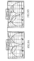
- Figs. 8a and 8b are graphs illustrating Azimuth (Az) radiation patterns prior to and after application of the ground connecting apparatus in accordance with the present invention, respectively.
- Zero (0) degrees represents a direction towards a user's head in radiation patterns.
- the Azimuth (Az) radiation pattern after application of the ground connecting apparatus shows that radiation in the direction of the user's head is reduced.
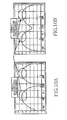
- Figs. 9a and 9b are graphs illustrating Elevation (E1) radiation patterns prior to and after application of the ground connecting apparatus in accordance with the present invention, respectively.
- the Elevation (E1) radiation pattern after application of the ground connecting apparatus shows that radiation in the direction of the user's head is reduced.
- Figs. 10a and 10b are graphs illustrating Elevation (E2) radiation patterns prior to and after application of the ground connecting apparatus in accordance with the present invention, respectively.
- the Elevation (E2) radiation pattern after application of the ground connecting apparatus shows that radiation in the direction of the user's head is reduced.
- the present invention provides a ground connecting apparatus for a mobile terminal, in which grounds formed on the terminal are directly or indirectly connected, providing the same effect as the direct connection therebetween in case that respective pads of the grounds are electrically short-circuited, and reducing gain of the terminal and decreasing radiation in a direction of a user's head. Further, the ground connecting apparatus adjusts an electrical connection length of the grounds using first and second connection elements, thereby reducing gain of the terminal to a desired degree and decreasing radiation in the direction of the user's head.
- the ground connecting apparatus of the present invention reduces an SAR value of the terminal, improves field performance of the terminal and adjusts radiation properties of an antenna of the terminal, thereby decreasing radiation in the direction of the user's head.
Applications Claiming Priority (2)
| Application Number | Priority Date | Filing Date | Title |
|---|---|---|---|
| KR2003055075 | 2003-08-08 | ||
| KR10-2003-0055075A KR100539935B1 (ko) | 2003-08-08 | 2003-08-08 | 휴대 단말기의 그라운드 연결장치 |
Publications (3)
| Publication Number | Publication Date |
|---|---|
| EP1505800A2 true EP1505800A2 (de) | 2005-02-09 |
| EP1505800A3 EP1505800A3 (de) | 2006-07-26 |
| EP1505800B1 EP1505800B1 (de) | 2007-12-05 |
Family
ID=33550338
Family Applications (1)
| Application Number | Title | Priority Date | Filing Date |
|---|---|---|---|
| EP04018736A Expired - Fee Related EP1505800B1 (de) | 2003-08-08 | 2004-08-06 | Vorrichtung zur Masseführung von einem klappbaren Mobilfunkgerät |
Country Status (5)
| Country | Link |
|---|---|
| US (1) | US7526083B2 (de) |
| EP (1) | EP1505800B1 (de) |
| KR (1) | KR100539935B1 (de) |
| CN (1) | CN100569058C (de) |
| DE (1) | DE602004010469T2 (de) |
Cited By (3)
| Publication number | Priority date | Publication date | Assignee | Title |
|---|---|---|---|---|
| EP1811598A1 (de) * | 2006-01-20 | 2007-07-25 | Samsung Electronics Co.,Ltd. | SAR-Wert-reduzierendes Element, mobiles Endgerät damit und Verfahren zu seiner Herstellung |
| WO2008150760A1 (en) * | 2007-05-31 | 2008-12-11 | Motorola, Inc. | Adjusting the electrical ground length of a communication device |
| EP2602974A1 (de) * | 2011-12-07 | 2013-06-12 | Samsung Electronics Co., Ltd | Zusammenklappbares mobiles Kommunikationssystem und die daran installierte Scharniervorrichtung |
Families Citing this family (19)
| Publication number | Priority date | Publication date | Assignee | Title |
|---|---|---|---|---|
| US7280856B2 (en) * | 2003-05-24 | 2007-10-09 | Samsung Electronics Co., Ltd. | Portable terminal having tuner for changing radiation pattern |
| JP4503618B2 (ja) * | 2005-01-21 | 2010-07-14 | パナソニック株式会社 | 携帯端末 |
| DE102007041859B4 (de) * | 2006-09-15 | 2011-12-01 | Lg Electronics Inc. | Mobiles Kommunikationsendgerät und Steuerungsverfahren dafür |
| KR100771159B1 (ko) * | 2006-10-31 | 2007-10-29 | 삼성전자주식회사 | 힌지 조립체 및 그를 갖는 이동통신 단말기 |
| JP4358267B2 (ja) * | 2007-10-31 | 2009-11-04 | パナソニック株式会社 | 携帯無線装置 |
| TWI347510B (en) * | 2008-06-20 | 2011-08-21 | Quanta Comp Inc | Electronic apparatus and hinge thereof |
| JP4463312B2 (ja) * | 2008-06-20 | 2010-05-19 | パナソニック株式会社 | 折り畳み式携帯端末および携帯端末 |
| CN101931158B (zh) * | 2009-06-24 | 2012-12-26 | 莫列斯公司 | 枢轴电连接器组合及具有该枢轴电连接器组合的电子装置 |
| KR101670258B1 (ko) * | 2009-07-06 | 2016-10-31 | 삼성전자 주식회사 | 연성 인쇄 회로 기판을 구비하는 휴대 단말기 |
| JP5532866B2 (ja) * | 2009-11-30 | 2014-06-25 | 船井電機株式会社 | マルチアンテナ装置および携帯機器 |
| CN101867385B (zh) * | 2010-06-21 | 2013-11-06 | 华为终端有限公司 | 无线通信设备 |
| JP5679743B2 (ja) * | 2010-09-10 | 2015-03-04 | キヤノン株式会社 | 電子機器 |
| CN102082849B (zh) * | 2011-01-24 | 2014-03-26 | 惠州硕贝德无线科技股份有限公司 | 一种翻盖手机内pcb板接地结构 |
| CN103441330A (zh) * | 2013-08-06 | 2013-12-11 | 华为终端有限公司 | 无线通信设备 |
| KR102181550B1 (ko) * | 2013-12-06 | 2020-11-23 | 삼성전자주식회사 | 노이즈 차단 구조를 갖는 전자 장치 |
| KR102367678B1 (ko) * | 2015-11-19 | 2022-02-28 | 삼성전자주식회사 | 힌지 장치를 구비하는 전자 장치 |
| CN108879070B (zh) * | 2018-06-29 | 2020-09-25 | 联想(北京)有限公司 | 一种电子设备 |
| US10877517B2 (en) * | 2018-09-11 | 2020-12-29 | Apple Inc. | Assembly for portable electronic device |
| KR102640610B1 (ko) * | 2019-02-19 | 2024-02-26 | 삼성전자 주식회사 | 통합된 접지 구조를 포함하는 폴더블 전자 장치 |
Citations (4)
| Publication number | Priority date | Publication date | Assignee | Title |
|---|---|---|---|---|
| US5508709A (en) * | 1993-05-03 | 1996-04-16 | Motorola, Inc. | Antenna for an electronic apparatus |
| US6272356B1 (en) * | 1999-05-10 | 2001-08-07 | Ericsson Inc. | Mechanical spring antenna and radiotelephones incorporating same |
| EP1258943A1 (de) * | 2001-05-08 | 2002-11-20 | Mitsubishi Denki Kabushiki Kaisha | Die Abschirmung als zweite Antenne verwendendes tragbares und klappbares Telefon |
| EP1329981A2 (de) * | 2002-01-18 | 2003-07-23 | Samsung Electronics Co., Ltd. | Aus einer wendelförmigen Gelenkfeder bestehende Antenneneinheit |
Family Cites Families (4)
| Publication number | Priority date | Publication date | Assignee | Title |
|---|---|---|---|---|
| JP2663591B2 (ja) * | 1988-12-12 | 1997-10-15 | 日本電気株式会社 | 回転部の接続構造 |
| KR100440407B1 (ko) * | 2002-07-19 | 2004-07-14 | 삼성전자주식회사 | 힌지 장치를 이용한 그라운드 접속 장치를 구비하는휴대용 무선 단말기 |
| KR100969747B1 (ko) * | 2003-01-06 | 2010-07-13 | 삼성전자주식회사 | 힌지 장치를 이용한 그라운드 접속 장치를 구비하는휴대용 무선 단말기 |
| US7280856B2 (en) * | 2003-05-24 | 2007-10-09 | Samsung Electronics Co., Ltd. | Portable terminal having tuner for changing radiation pattern |
-
2003
- 2003-08-08 KR KR10-2003-0055075A patent/KR100539935B1/ko not_active IP Right Cessation
-
2004
- 2004-07-19 US US10/894,160 patent/US7526083B2/en not_active Expired - Fee Related
- 2004-08-06 EP EP04018736A patent/EP1505800B1/de not_active Expired - Fee Related
- 2004-08-06 CN CNB2004100565249A patent/CN100569058C/zh not_active Expired - Fee Related
- 2004-08-06 DE DE602004010469T patent/DE602004010469T2/de active Active
Patent Citations (4)
| Publication number | Priority date | Publication date | Assignee | Title |
|---|---|---|---|---|
| US5508709A (en) * | 1993-05-03 | 1996-04-16 | Motorola, Inc. | Antenna for an electronic apparatus |
| US6272356B1 (en) * | 1999-05-10 | 2001-08-07 | Ericsson Inc. | Mechanical spring antenna and radiotelephones incorporating same |
| EP1258943A1 (de) * | 2001-05-08 | 2002-11-20 | Mitsubishi Denki Kabushiki Kaisha | Die Abschirmung als zweite Antenne verwendendes tragbares und klappbares Telefon |
| EP1329981A2 (de) * | 2002-01-18 | 2003-07-23 | Samsung Electronics Co., Ltd. | Aus einer wendelförmigen Gelenkfeder bestehende Antenneneinheit |
Cited By (4)
| Publication number | Priority date | Publication date | Assignee | Title |
|---|---|---|---|---|
| EP1811598A1 (de) * | 2006-01-20 | 2007-07-25 | Samsung Electronics Co.,Ltd. | SAR-Wert-reduzierendes Element, mobiles Endgerät damit und Verfahren zu seiner Herstellung |
| US7672698B2 (en) | 2006-01-20 | 2010-03-02 | Samsung Electronics Co., Ltd. | Specific absorption rate reducer, mobile terminal using the same and method therefor |
| WO2008150760A1 (en) * | 2007-05-31 | 2008-12-11 | Motorola, Inc. | Adjusting the electrical ground length of a communication device |
| EP2602974A1 (de) * | 2011-12-07 | 2013-06-12 | Samsung Electronics Co., Ltd | Zusammenklappbares mobiles Kommunikationssystem und die daran installierte Scharniervorrichtung |
Also Published As
| Publication number | Publication date |
|---|---|
| DE602004010469D1 (de) | 2008-01-17 |
| EP1505800B1 (de) | 2007-12-05 |
| US7526083B2 (en) | 2009-04-28 |
| KR100539935B1 (ko) | 2005-12-28 |
| CN1582106A (zh) | 2005-02-16 |
| KR20050017765A (ko) | 2005-02-23 |
| EP1505800A3 (de) | 2006-07-26 |
| CN100569058C (zh) | 2009-12-09 |
| DE602004010469T2 (de) | 2008-04-30 |
| US20050030233A1 (en) | 2005-02-10 |
Similar Documents
| Publication | Publication Date | Title |
|---|---|---|
| US7526083B2 (en) | Ground connecting apparatus for mobile terminal | |
| US7705789B2 (en) | Portable wireless device | |
| US5945954A (en) | Antenna assembly for telecommunication devices | |
| US7526326B2 (en) | Handheld wireless communicators with reduced free-space, near-field emissions | |
| US6806835B2 (en) | Antenna structure, method of using antenna structure and communication device | |
| EP1482646B1 (de) | Tragbares Endgerät mit Abstimmeinrichtung zum Ändern der Strahlungscharakteristik | |
| KR100908188B1 (ko) | 절첩식 휴대형 무선기 및 그 무선기의 섀시 | |
| US6590539B2 (en) | Antenna device in radio communication terminal | |
| EP1750323A1 (de) | Mehrbandantennenvorrichtung für ein Funkkommunikationsendgerät, und Funkkommunikationsendgerät mit einer solchen Mehrbandantennenvorrichtung | |
| EP1962378B1 (de) | Breitbandantenneneinheit mit einem gefalteten plattenförmigen Monopolantennenteil und einem ausziehbaren Teil | |
| US7050009B2 (en) | Internal antenna | |
| JP2007538459A (ja) | 別々の低周波数帯アンテナを複数含むマルチバンドアンテナシステムとそれを組み込んだ無線端末及び無線電話機 | |
| JPWO2007043138A1 (ja) | 折畳式携帯無線装置 | |
| JPWO2006057350A1 (ja) | 折畳式携帯無線装置 | |
| US7642966B2 (en) | Carrier and device | |
| EP1686647B1 (de) | Mobilkommunikationsendgerät | |
| US7301499B2 (en) | Built-in type antenna apparatus for portable terminal | |
| EP2043195A1 (de) | Breitbandantenneneinheit mit einem gefalteten plattenförmigen Monopolantennenabschnitt und zwei leitenden Elementen | |
| EP1646108B1 (de) | Antennenmodul für ein tragbares drahtloses Endgerät | |
| EP1634349B1 (de) | Eingebaute antenne mit mittenzuleitungsstruktur für ein drahtloses endgerät | |
| JP4189433B1 (ja) | 携帯無線機 | |
| EP2234203B1 (de) | Mobile Vorrichtung | |
| KR100584399B1 (ko) | 방사 패턴 변경용 튜닝부를 구비하는 휴대용 단말기 | |
| JP2004343165A (ja) | アンテナ装置及び無線通信機器 |
Legal Events
| Date | Code | Title | Description |
|---|---|---|---|
| PUAI | Public reference made under article 153(3) epc to a published international application that has entered the european phase |
Free format text: ORIGINAL CODE: 0009012 |
|
| 17P | Request for examination filed |
Effective date: 20040806 |
|
| AK | Designated contracting states |
Kind code of ref document: A2 Designated state(s): AT BE BG CH CY CZ DE DK EE ES FI FR GB GR HU IE IT LI LU MC NL PL PT RO SE SI SK TR |
|
| AX | Request for extension of the european patent |
Extension state: AL HR LT LV MK |
|
| PUAL | Search report despatched |
Free format text: ORIGINAL CODE: 0009013 |
|
| AK | Designated contracting states |
Kind code of ref document: A3 Designated state(s): AT BE BG CH CY CZ DE DK EE ES FI FR GB GR HU IE IT LI LU MC NL PL PT RO SE SI SK TR |
|
| AX | Request for extension of the european patent |
Extension state: AL HR LT LV MK |
|
| RIC1 | Information provided on ipc code assigned before grant |
Ipc: H04M 1/02 20060101AFI20041119BHEP Ipc: H04B 1/38 20060101ALI20060616BHEP Ipc: H01Q 1/02 20060101ALI20060616BHEP |
|
| 17Q | First examination report despatched |
Effective date: 20061005 |
|
| AKX | Designation fees paid |
Designated state(s): DE FR GB |
|
| GRAP | Despatch of communication of intention to grant a patent |
Free format text: ORIGINAL CODE: EPIDOSNIGR1 |
|
| GRAS | Grant fee paid |
Free format text: ORIGINAL CODE: EPIDOSNIGR3 |
|
| GRAA | (expected) grant |
Free format text: ORIGINAL CODE: 0009210 |
|
| AK | Designated contracting states |
Kind code of ref document: B1 Designated state(s): DE FR GB |
|
| REG | Reference to a national code |
Ref country code: GB Ref legal event code: FG4D |
|
| REF | Corresponds to: |
Ref document number: 602004010469 Country of ref document: DE Date of ref document: 20080117 Kind code of ref document: P |
|
| ET | Fr: translation filed | ||
| PLBE | No opposition filed within time limit |
Free format text: ORIGINAL CODE: 0009261 |
|
| STAA | Information on the status of an ep patent application or granted ep patent |
Free format text: STATUS: NO OPPOSITION FILED WITHIN TIME LIMIT |
|
| 26N | No opposition filed |
Effective date: 20080908 |
|
| REG | Reference to a national code |
Ref country code: FR Ref legal event code: PLFP Year of fee payment: 13 |
|
| REG | Reference to a national code |
Ref country code: FR Ref legal event code: PLFP Year of fee payment: 14 |
|
| PGFP | Annual fee paid to national office [announced via postgrant information from national office to epo] |
Ref country code: DE Payment date: 20170720 Year of fee payment: 14 Ref country code: GB Payment date: 20170720 Year of fee payment: 14 Ref country code: FR Payment date: 20170724 Year of fee payment: 14 |
|
| REG | Reference to a national code |
Ref country code: DE Ref legal event code: R119 Ref document number: 602004010469 Country of ref document: DE |
|
| GBPC | Gb: european patent ceased through non-payment of renewal fee |
Effective date: 20180806 |
|
| PG25 | Lapsed in a contracting state [announced via postgrant information from national office to epo] |
Ref country code: DE Free format text: LAPSE BECAUSE OF NON-PAYMENT OF DUE FEES Effective date: 20190301 |
|
| PG25 | Lapsed in a contracting state [announced via postgrant information from national office to epo] |
Ref country code: FR Free format text: LAPSE BECAUSE OF NON-PAYMENT OF DUE FEES Effective date: 20180831 |
|
| PG25 | Lapsed in a contracting state [announced via postgrant information from national office to epo] |
Ref country code: GB Free format text: LAPSE BECAUSE OF NON-PAYMENT OF DUE FEES Effective date: 20180806 |