EP1505366A2 - Verfahren zur Einstellung einer Schaltschwelle eines Tastschalters - Google Patents
Verfahren zur Einstellung einer Schaltschwelle eines Tastschalters Download PDFInfo
- Publication number
- EP1505366A2 EP1505366A2 EP04010414A EP04010414A EP1505366A2 EP 1505366 A2 EP1505366 A2 EP 1505366A2 EP 04010414 A EP04010414 A EP 04010414A EP 04010414 A EP04010414 A EP 04010414A EP 1505366 A2 EP1505366 A2 EP 1505366A2
- Authority
- EP
- European Patent Office
- Prior art keywords
- value
- system parameter
- switching threshold
- difference
- rest
- Prior art date
- Legal status (The legal status is an assumption and is not a legal conclusion. Google has not performed a legal analysis and makes no representation as to the accuracy of the status listed.)
- Granted
Links
- 238000000034 method Methods 0.000 title claims abstract description 41
- 238000012937 correction Methods 0.000 claims abstract description 36
- 230000008859 change Effects 0.000 claims description 58
- 239000000523 sample Substances 0.000 claims description 46
- 230000000284 resting effect Effects 0.000 claims description 39
- 230000007423 decrease Effects 0.000 claims description 20
- 230000001965 increasing effect Effects 0.000 claims description 13
- 230000001419 dependent effect Effects 0.000 claims description 2
- 238000006073 displacement reaction Methods 0.000 claims description 2
- 241001422033 Thestylus Species 0.000 description 52
- 230000008569 process Effects 0.000 description 11
- 230000003287 optical effect Effects 0.000 description 9
- 230000000694 effects Effects 0.000 description 6
- 239000000463 material Substances 0.000 description 3
- 230000009467 reduction Effects 0.000 description 3
- 230000009471 action Effects 0.000 description 2
- 230000004913 activation Effects 0.000 description 2
- 238000013459 approach Methods 0.000 description 2
- 230000008901 benefit Effects 0.000 description 2
- 238000011156 evaluation Methods 0.000 description 2
- 238000005259 measurement Methods 0.000 description 2
- 239000002184 metal Substances 0.000 description 2
- 238000003801 milling Methods 0.000 description 2
- 238000012360 testing method Methods 0.000 description 2
- 101100453960 Drosophila melanogaster klar gene Proteins 0.000 description 1
- 230000006978 adaptation Effects 0.000 description 1
- 230000004888 barrier function Effects 0.000 description 1
- 230000006835 compression Effects 0.000 description 1
- 238000007906 compression Methods 0.000 description 1
- 238000010276 construction Methods 0.000 description 1
- 230000003111 delayed effect Effects 0.000 description 1
- 238000010586 diagram Methods 0.000 description 1
- 230000001771 impaired effect Effects 0.000 description 1
- 230000001939 inductive effect Effects 0.000 description 1
- 238000003754 machining Methods 0.000 description 1
- 238000012545 processing Methods 0.000 description 1
Images


Classifications
-
- G—PHYSICS
- G01—MEASURING; TESTING
- G01B—MEASURING LENGTH, THICKNESS OR SIMILAR LINEAR DIMENSIONS; MEASURING ANGLES; MEASURING AREAS; MEASURING IRREGULARITIES OF SURFACES OR CONTOURS
- G01B11/00—Measuring arrangements characterised by the use of optical techniques
- G01B11/002—Measuring arrangements characterised by the use of optical techniques for measuring two or more coordinates
- G01B11/005—Measuring arrangements characterised by the use of optical techniques for measuring two or more coordinates coordinate measuring machines
- G01B11/007—Measuring arrangements characterised by the use of optical techniques for measuring two or more coordinates coordinate measuring machines feeler heads therefor
-
- G—PHYSICS
- G01—MEASURING; TESTING
- G01B—MEASURING LENGTH, THICKNESS OR SIMILAR LINEAR DIMENSIONS; MEASURING ANGLES; MEASURING AREAS; MEASURING IRREGULARITIES OF SURFACES OR CONTOURS
- G01B21/00—Measuring arrangements or details thereof, where the measuring technique is not covered by the other groups of this subclass, unspecified or not relevant
- G01B21/02—Measuring arrangements or details thereof, where the measuring technique is not covered by the other groups of this subclass, unspecified or not relevant for measuring length, width, or thickness
- G01B21/04—Measuring arrangements or details thereof, where the measuring technique is not covered by the other groups of this subclass, unspecified or not relevant for measuring length, width, or thickness by measuring coordinates of points
- G01B21/045—Correction of measurements
Definitions
- the invention relates to a method for setting a switching threshold of a Push-button switch according to the preamble of claim 1.
- Such a tact switch also called touch probe
- a deflectable Tastelement is at a deflection of the probe element from its rest position Switching signal off.
- key switches for example, for position determination used by workpieces used in material processing machines, in particular Milling machines are clamped.
- an (electrical) System parameters of the key switch measured, e.g. in the form of an electric Voltage that drops across contacts arranged in the key switch.
- the key switch When deflecting of the probe element from its rest position causes the key switch a change of said system parameters, that is, for example, the falling over the contacts Tension. If the system parameter in this case a predetermined switching threshold exceeds, then the key switch outputs a switching signal, which is a deflection of the Tastelementes and thus indicates the contact with a workpiece.
- a push-button switch of the type mentioned has means with which the Difference between the switching threshold and the value of the system parameter in the Rest position of the probe element can be set to a predetermined difference value can. This is necessary because of material wear and impact humidity and temperature, the rest position of the probe element is not complete remains constant, but slightly in the operation of the pushbutton with time changes. That is, the actually occupied during operation of the key switch Rest position of the probe element deviates with increasing age of the key switch slightly from the ideal resting position, which has a certain value of System parameters (for example, the at the electrical contacts of the Tastschalters falling voltage) is assigned. This causes the System parameter in the actual rest position of the probe element from the ideal rest value deviating value.
- System parameters for example, the at the electrical contacts of the Tastschalters falling voltage
- a deflection of the probe element is not detected correctly or not deflected probe element is mistakenly considered deflected.
- a switching threshold as a measure of whether a deflection of the Tastelementes exists or not.
- the value of the system parameter changes in the Rest position of the probe element by material wear and the action of Moisture and temperature, in particular, the difference between the changes Switch threshold of the system parameter and its value in the rest position of the scanning element; And this difference determines just the triggering threshold, from which the Tastschalter a contact of the probe element with a workpiece by delivering a Switching signals indicates.
- From DE 109 29 557 A1 discloses a method and a circuit for adjusting a Switching threshold of a key switch known in which the switching threshold of Pushbutton to one of the value of the system parameter in the rest position of the Probe element dependent value is set to the difference between the Switching threshold and the resting value of the system parameter to be kept constant. For this is it is necessary for an adjustment (tracking) of the switching threshold respectively to ensure that the probe is actually in a rest position.
- the invention is based on the problem, a method for adjusting the Switching threshold of a key switch of the type mentioned further improve.
- the resting value of the system parameter is not reduced but increased.
- the control device of the button for example in the form of a Microprocessor
- the control device of the button are set up (programmed) for the purpose of Reset the switching threshold a change in the difference between the Threshold and the resting value of the system parameter exclusively along the allows said first direction of the number beam.
- the solution according to the invention is based on the knowledge that the quiescent value of the System parameters in the operation of a push-button as a result of wear always only changes along one direction, for example continuously during operation (slightly) decreases. This is due to the storage of the probe element in the housing of the Key switch by means of a ball bearing whose wear to a defined change the position of the probe element in the housing of the pushbutton leads. This on wear declining change in the position of the probe element in its rest position (ie in undeflected state) in turn leads to a defined change in the Rest of the system parameter, so for example, to a steady decrease in Value of the system parameter in the rest position of the probe element.
- a continuous (minor) decrease of below the switching threshold Resting value of the system parameter in turn means that the amount of the Difference between the switching threshold and the resting value of the system parameter continuously (slightly) increases.
- this difference must be regularly reduced somewhat.
- This can on the one hand by an adaptation (in the present example by a reduction) the switching threshold of the system parameter or alternatively by a correction the idle value of the system parameter by changing the system parameter (and thus especially its quiescent value) a correction value is superimposed, so that the Difference between the switching threshold and the (applied with the correction value) Rest value is closer to the predetermined difference value.
- this is equivalent to increasing the quiescent value of the system parameter Addition of a correction value (by the difference increasing due to wear) Threshold and rest value of the system parameter back to the specified To set difference value).
- the solution according to the invention has the advantage that it is due to the consideration the direction of the wear-related change in the rest value of the system parameter (and thus also the difference between the switching threshold and the quiescent value) simple distinction between a deflection of the probe element in the present example leads to an increase in the value of the system parameter, and a wear-related change in the rest position of the probe element, which leads to a Decrease in the resting value of the system parameter allows.
- a correction of Difference between switching threshold and rest value of the system parameter is thereafter always required if the currently measured value of the system parameter along one direction deviates from the nominal rest value, that of the direction is opposite, along which the system parameter at a deflection of the Tastelementes changed.
- the value of the System parameter understood by the system parameter in the rest position of Tastelementes should have, so that the difference between the switching threshold and the Resting value of the system parameter corresponds to the predetermined difference value. comes So it is in operation due to a wear-related change in the rest position of Tastelemetes tends to decrease the resting value, this means that the Difference between the (above the rest value of the system parameter) Switching threshold and the current quiescent value is greater than the default Difference value. The difference between switching threshold and quiescent value of System parameter must then be adjusted so that it returns to the corresponds to the predetermined difference value.
- an electrical system parameter e.g. in form of a electrical voltage
- a sensor associated with the probe element and optionally a downstream amplifier
- a corresponding sensor signal e.g. Form of an amplified voltage signal
- the present invention is included regardless of the sensor principle used, both on one non-contact sensor (e.g., an optical sensor in the form of a light barrier or a magnetic sensor) as well as on a the touch of the sensor by the Tastelement underlying (eg electrical) sensor principle can be based.
- the setting of the difference between the switching threshold and the quiescent value of the Systemparameters preferably takes place in such a way that at certain, specifiable Times at startup of the push-button and / or during operation of the push-button the current value of the system parameter in each case with the setpoint of the System parameter is compared in the rest position and that the difference between the switching threshold and the idle value of the system parameter are always changed when the current value of the system parameter is from the target quiescent value one of the initially defined, first direction of the number beam opposite Direction deviates, so according to the presently explained example, the current value of the system parameter is less than the target quiescent value.
- a battery operated pushbutton will re-adjust the difference between switching threshold and resting value of the system parameter preferably after each Battery replacement. Because it is assumed that to carry out a Battery change regularly consulted the tactile switch associated manual and the user accordingly the key switch before the renewed Commissioning after a battery change according to the specification is sufficient Time is available to any necessary adjustment of the switching threshold by subtracting the difference between the switching threshold and the quiescent value of the System parameter is reset.
- the comparison between the current value of the system parameter and the desired resting value and the possibly required setting of the switching threshold with a predetermined clock frequency e.g. at a time interval between 10ms and 30ms, until repeated, until no deviation of the current value of the system parameter
- a predetermined clock frequency e.g. at a time interval between 10ms and 30ms
- the time interval between two Compare the current value of the system parameter with the set value Preferably, depending on when the difference between the switching threshold and the Resting value of the system parameter has been last changed. So can be provided that a process that compares the currently measured value of the System parameter with the nominal rest value and, if necessary, a change in the Difference between switching threshold and resting value of the system parameter results in one time interval is initiated by the clock frequency of the control of the Process serving microprocessor is specified. Is this due to a these comparisons actually lead to a change in the difference between switching threshold and rest value of the system parameter, the next comparison will be in one delayed, greater time interval, z. B. several minutes.
- a readjustment of the difference between switching threshold and quiescent value of the System parameter takes place during operation of the pushbutton among the above (am Example of a new commissioning of the pushbutton) specified conditions for the deviation of the current value of the system parameter from the nominal rest value.
- These two ways of resetting the difference between switching threshold and resting value of the system parameter are independent of it of importance, whether the difference between the switching threshold and the resting value, such as provided in the present invention exclusively along one direction of the Number beam is changed. Rather, it opens up in a process for adjustment a switching threshold of a push-button basically the way, depending on the Circuitry circumstances in each case, either the switching threshold itself or adjust the sleep value of the system parameter accordingly.
- the respective change can on the one hand in constant, immutable steps or on the other hand depending on the deviation of the currently measured Resting value of the system parameter from its nominal rest value.
- the change can then be done in such a way that in each case only a certain percentage (smaller or equal to 100%) of the deviation of the currently measured quiescent value of the System parameter is compensated by the target rest value, for example 50%. This ensures that the newly set idle value is never exceeded can be the desired resting value.
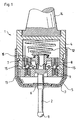
- Figure 1 shows a key switch 1, which is used to determine the position of a in a Machine clamped workpiece, for example, one in a milling machine clamped workpiece is used.
- the key switch 1 is by means of a cone 14 inserted into a spindle of the machine. To make a firm connection of the To secure the key switch 1 with the spindle, the cone 14 is attached to a housing 4 of the Push-button 1 fixed.
- a probe element in the form of a stylus 2 with a Probe ball 11, which by means of a ball bearing 15 in all directions movable in the Housing 4 is mounted, ie in the vertical direction.
- the space between the housing 4 of the key switch 1 and the stylus 2 is by a seal. 3 locked.
- a sheet metal protection 5 is arranged around the stylus 2, the Damage of the seal 3 by chips, during machining of the workpiece should arise, prevent.
- the sheet metal protection has 5 an opening 6, which is a deflection of the stylus 2 from its rest position allows.
- the rest position of the stylus 2 is usually on the axis of symmetry of the key switch 1, as shown in Figure 1.
- the stylus 2 is firmly connected to a Tasthalter 10.
- a compression spring 12 is arranged, with its other end on the housing 4 of the Push-button 1 is applied.
- Housing bottom 13 of the housing 4 of the key switch 1 the above-mentioned ball bearing 15 provided.
- the detector arrangement has for this purpose a fixed optical transmitter 7, which is designed as an LED, as well as a thereto aligned, also fixed differential photoelement 9.
- a Lens system 8 fixed to the movable stylus 2.
- a deflection of the stylus 2 leads to a change in the Output current of the differential photoelement 9, from which by means of a suitable Amplifier a measurable change of a corresponding voltage is generated.
- the change of the output voltage is an image of Change of the output current and thus also the light intensity at the Differential Photoelement 9. This is shortened here as a change of the output voltage of the differential photoelement 9 due to a deflection of the stylus 2.
- optical detector arrangement can be in connection with the present invention, other detectors are also used e.g. based on magnetic, inductive or capacitive principles. Because the The invention relates to the adjustment of the switching threshold of the key switch 1 and is regardless of the type of detector used.
- the output voltage and the probing process are shown in FIG.
- the output voltage U SE of the differential photoelement 9 is generally constant and corresponds to a voltage which is referred to below as rest voltage U R. Only upon deflection of the stylus 2 due to the contact of the probe ball 11 of the stylus 2 with the workpiece, the output voltage U SE increases .
- a switching threshold U S When a switching threshold U S is exceeded, a switching signal is generated by the key switch 1, which is forwarded to an evaluation unit, not shown here.
- the switching threshold U S is chosen such that it has a value U D greater than the rest voltage U R by an amount.
- the amount U D does not have to be a constant. It is only important that U D is chosen such that the switching threshold U S deviates from the rest voltage U R , ie the output voltage U SE of the differential photoelement 9 in the rest position of the stylus 2 in order to ensure the proper functioning of the pushbutton 1.
- the rest voltage U R shown in Figure 2 is not always constant, but it is - seen over a longer period - subject to drift.
- the reason for this is that the stylus 2 does not always return to the original rest position after a deflection, but instead can assume a position deviating therefrom, ie a new rest position. This is due to mechanical wear of the key switch 1, but also due to the action of moisture and temperature on the key switch 1. This results in the rest position of the stylus 2 to a change in the relative position of the optical sensor 7, the lens pair 8 and the differential photo element 9 to each other, which leads to a change and thus drift of the quiescent voltage U R.
- FIG. 2 This effect is illustrated in FIG. 2 by way of example with reference to the dashed line, which represents a rest voltage of the momentary-contact switch reduced by a value U DR as a result of wear. This corresponds to an increase in the difference between the switching threshold U S and the quiescent voltage by just that value U DR . It can also be seen from the dashed curve that due to this displacement of the rest voltage U R to smaller voltage values, the deflection S, at which the momentary-contact switch 1 outputs a switching signal, is shifted toward greater values. (The corresponding deflections at which the switching signal is generated are shown in FIG. 2 in each case from the point of intersection of the measured output voltage U SE with the switching threshold U S. )
- a deflection of the stylus 2 - corresponding to the course of the output voltage U SE of the differential photoelement 9 shown in FIG. 2 - has exactly the opposite effect, namely an increase of the output voltage U SE of the differential photoelement 9.
- a deflection of the stylus 2 causes the area of the stylus 2 (namely, the lens system 8) scanned by the optical transmitter 7 and the differential photoelement 9 to be moved away from the housing bottom 13 along the extension direction of the stylus 2.
- a deflection of the stylus 2 always causes the area of the stylus 2 scanned by the optical transmitter 7 and the differential photoelement 9 to move away from the housing bottom 13. This is exactly opposite to the tendency of the scanned area of the stylus 2 to approach the housing bottom 13 as a result of wear, which leads to wear of the ball bearing 15 and thus to a reduction in the distance between the feeler holder 10 and the housing bottom 13.
- FIG. 3 shows a circuit arrangement for setting the difference between the switching threshold U S and the quiescent voltage U R of a push-button switch to a given difference value U D.
- the differential photoelement 9 of the key switch 1 which generates a deflection of the stylus 2 corresponding output signal in the form of a current
- an amplifier 21 for amplifying the output signal of the Differenzialphotoides 9 downstream, which generates the relevant output voltage U SE , the present also simply as an output voltage of the differential photoelement 9 is designated.
- the amplifier 21 is in turn connected on the output side to a trigger 22, to whose one input the amplified output signal of the differential photoelement 9 is applied.
- the trigger 22 serves to compare the respectively measured, amplified output voltage of the differential photoelement 9 with a switching threshold, such that an exceeding of the switching threshold triggers a switching signal.
- This switching signal is supplied to a microprocessor 25, with which the trigger 22 is connected on the output side.
- the microprocessor 25 is followed by a suitable transmitting device 26, 27, for example in the form of an infrared transmitter.
- the microprocessor 25 receives from an additional trigger 24 (reset module) Information about whether the battery voltage of the battery-powered Pushbutton is above a certain minimum value. This can be determined be whether at any given time in the key switch a battery is present.
- a new setting of the switching threshold or more precisely the difference between Switching threshold and rest voltage at a battery change is advantageous because certain defined steps have to be executed when changing the battery, which is usually the tactile switch associated manual is consulted.
- a counter of the microprocessor is set to zero and then measured the output voltage U SE of the differential photoelement 9, it can be assumed that it is the output voltage U SE in the rest position of the stylus 2.
- the measured behind the amplifier 21 output voltage U SE is thereby supplied to the microprocessor 25 by means of an analog / digital converter.
- the setpoint value of the quiescent voltage U R is understood to be that voltage with which the desired difference value U D between the switching threshold U S and the quiescent voltage U R is achieved.
- the setpoint value of the quiescent voltage U R is a constant.
- the comparison 104 shows that the measured output voltage U SE of the differential photoelement 9 is not smaller than the setpoint value of the quiescent voltage U R , then the method for readjusting the difference between the switching threshold U S and the quiescent voltage U R is aborted immediately. 110there after a battery change It is assumed that the stylus 2 is not deflected, so there is no effect on the output voltage U SE of the differential photoelement 9 by deflection of the stylus 2, the above result of the comparison 104 indicates that the current value of the output voltage U SE at not deflected, located in its rest position stylus has not dropped below the setpoint of the rest voltage U R.
- the individual correction values, which are added to the output voltage U SE at the amplifier 21 in each case, are constant values. That is, with each measured below the setpoint value of the rest voltage U R , a corresponding, constant correction value is added to the output voltage of the amplifier 21. This is optionally repeated until a comparison reveals that the measured in the rest position of the stylus 2 output voltage U SE no longer falls below (taking into account the added correction values) the target value of the rest voltage U R.
- the individual correction values, which are added by the value 1 to the output voltage of the amplifier 21 with each increase of the counter, are chosen so small that they do not cause the switching threshold U S of the key switch to be exceeded.
- the addition of a correction value to the output voltage of the amplifier 21 can not be misinterpreted as a deflection of the stylus 2 and thus can not lead to the accidental delivery of a switching signal.
- the added correction values - corresponding to the count at the conclusion of the readjustment of the switching threshold - determine the new value of the rest voltage U R.
- the increase of the output voltage U SE of the amplifier 21 may also be effected in steps which are adapted to the difference between the desired value and the measured actual value of the rest voltage U R determined in the respective comparison 104.
- the correction value which in each case is added to the output voltage U SE at the amplifier 21, then results from the multiplication of the difference measured in the comparison 104 by a factor which is less than or equal to 1; it therefore forms a fraction of the difference determined.
- the difference between switching threshold U S and rest voltage U R is then set for a recording of the operation of the push-button switch after the battery change to the desired, predetermined difference value.
- the amplified by the amplifier 21 output voltage U SE of the differential photoelement 9 is measured and a comparison 202 performed with the setpoint of the rest voltage U R. If the measured output voltage U SE lies below the setpoint value of the quiescent voltage U R , this can only be attributed to the fact that the quiescent voltage U R has dropped due to wear. Accordingly, in turn, the count in the counter of the microprocessor 25 is increased and added in accordance with the increase of the count a correction value to the output voltage U SE of the amplifier 21, ie the accumulated (the output voltage added) correction values are increased by one unit, ie an additional correction value.
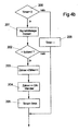
- a clock (“timer") of the microprocessor 25 is set in a next step 205 to a certain predetermined value, for example 5 minutes.
- a further comparison of the currently measured value of the output voltage U SE with the setpoint value of the quiescent voltage U R takes place after addition of a correction value to the output voltage U SE of the amplifier 21 only when the corresponding period of, for example, 5 minutes, has expired corresponding queries 200 and time updating 206 of the clock is ensured.
- the activation of the above process can be carried out in a simple manner at a time interval (of, for example, 0.25 ms), which is predetermined by the clock frequency of the microprocessor 25 used (eg 4 kHz).
- a time interval of, for example, 0.25 ms
- the process described with reference to FIG. 4b is basically activated at a time interval (of, for example, 0.25 ms) which corresponds to the clock frequency of the microprocessor used.
- the stylus 2 should be just deflected and this deflection should superimpose a decrease in the actual rest voltage U R below its target value, then it is ensured that in one of the next queries, which are regularly at certain times, for example all 0.25 ms takes place, the decrease in the rest voltage U R is detected if there is no deflection of the stylus at the appropriate time.
- a manipulation is in this case at best conceivable if the probe pin 2 is pulled contrary to the explicit instructions in the specification of the key switch 1, so that the distance between the key holder 10 and the housing bottom 13 is artificially reduced, which in the comparison 202 falsely as a assumed decrease in the rest voltage U R would be interpreted.
- a manipulation can not therefore lead to substantial problems in the setting of the switching threshold, since during operation of the probe system a corresponding check and adjustment of the switching threshold (by one step, ie adding a correction value) is carried out in each case only every 5 minutes. That is, a manipulation on the stylus 2, unless it is maintained for a longer period of more than 5 minutes, can only lead to a one-time correction of the output voltage U SE of the amplifier 21 with a (correspondingly small) correction value.
Landscapes
- Physics & Mathematics (AREA)
- General Physics & Mathematics (AREA)
- Measurement Of Length, Angles, Or The Like Using Electric Or Magnetic Means (AREA)
- Keying Circuit Devices (AREA)
- Lock And Its Accessories (AREA)
- Channel Selection Circuits, Automatic Tuning Circuits (AREA)
- Electronic Switches (AREA)
Abstract
Description
- Figur 1
- einen Längsschnitt durch einen Tastschalter zur Bestimmung der Position eines Werkstückes;
- Figur 2
- eine schematische Darstellung eines Spannungsverlaufs bei Annäherung eines Tastelementes des Tastschalters aus Figur 1 an ein Werkstück;
- Figur 3
- ein Blockschaltbild einer Schaltungsanordnung zur Einstellung der Schaltschwelle des Tastschalters;
- Figur 4a
- ein Flussdiagramm betreffend die Einstellung der Schaltschwelle des Tastschalters nach einem Batteriewechsel;
- Figur 4b
- ein Flussdiagramm betreffend die Einstellung der Schaltschwelle des Tastschalters im laufenden Betrieb.
- Wird der Tastschalter 1 zu einem gegebenen Ausgangszeitpunkt mit einer gegebenen Ruhespannung UR betrieben, so ist jede gemessene Spannung, die oberhalb dieser Ruhespannung UR liegt, auf eine Auslenkung des Taststiftes 2 zurückzuführen. Umgekehrt ist jeder gemessene Spannungswert, der unterhalb der ursprünglichen Ruhespannung UR liegt, auf eine Absenkung der Ruhespannung als Folge von Verschleiß zurückzuführen. Hierdurch lassen sich die Auswirkungen einer Auslenkung des Taststiftes 2 einerseits und von Verschleiß der Anordnung andererseits auf die gemessene Ausgangsspannung des Differenzialphotoelementes 9 klar trennen.
- Es ist nicht erforderlich, bei der laufenden Überprüfung, ob ein Absenken der Ruhespannung UR als Folge von Verschleiß eingetreten ist, sicherzustellen, dass sich der Taststift 2 bei der jeweiligen Prüfung tatsächlich im Ruhezustand befindet. Denn ist der Taststift zum Zeitpunkt einer entsprechenden Überprüfung ausgelenkt, so führt dies dazu, dass die Ausgangsspannung USE des Differenzialphotoelementes 9 gegenüber der Ruhespannung UR vergrößert ist. Dies lässt sich auf der Grundlage der obigen Beobachtungen unmittelbar einer Auslenkung des Taststiftes 2 zuordnen, so dass eine Verwechslung mit einer Änderung der Ruhespannung UR durch Verschleiß ausgeschlossen ist. Umgekehrt lässt sich eine Absenkung der Ruhespannung UR als Folge von Verschleiß eindeutig daran erkennen, dass ein gemessener Wert der Ausgangsspannung USE des Differenzialphotoelementes 9 unterhalb der ursprünglichen Ruhespannung UR liegt. Denn ein solcher Effekt kann nicht auf eine Auslenkung des Taststiftes 2 zurückzuführen sein, die ja ausschließlich zu einer Zunahme der Ausgangsspannung USE des Differenzialphotoelementes 9 führt.
- Im Ergebnis braucht also zur Feststellung einer Absenkung der Ruhespannung UR als Folge von Verschleiß lediglich in regelmäßigen zeitlichen Abständen überprüft zu werden, ob der aktuelle Wert der Ausgangsspannung USE niedriger ist als der zuletzt gültige Wert der Ruhespannung UR (Soll-Ruhewert). Wird eine Unterschreitung des Soll-Ruhewertes durch eine aktuell gemessene Ausgangsspannung USE des Differenzialphotoelementes 9 ermittelt, so lässt sich daraus zweifelsfrei der Schluss ziehen, dass eine Absenkung der Ruhespannung UR erfolgt ist und es kann eine entsprechende Korrektur durchgeführt werden.
- Wird demgegenüber bei einer der Prüfungen ein Wert der Ausgangsspannung USE des Differenzialphotoelementes 9 ermittelt, der oberhalb des Soll-Ruhewertes der Ruhespannung UR liegt, so ist dies eindeutig einer Auslenkung des Taststiftes 2 zuzuschreiben und es erfolgt keine Neueinstellung der Schaltschwelle des Taststiftes. Das Gleiche gilt selbstverständlich, wenn eine aktuell gemessene Ausgangsspannung USE des Differenzialphotoelementes 9 der zuletzt gültigen Ruhespannung UR entspricht; dies deutet auf eine unveränderte Ruhespannung UR hin.
- Falls zum Zeitpunkt einer Überprüfung der Ausgangsspannung USE des Differenzialphotoelementes 9 eine verschleißbedingte Absenkung der Ruhespannung UR von einer Auslenkung des Taststiftes 2 überlagert sein sollte, so kann zu diesem Zeitpunkt die tatsächliche Änderung der Ruhespannung UR selbstverständlich nicht korrekt erkannt werden. Indem jedoch die Abfrage der Ausgangsspannung USE des Differenzialphotoelementes 9, mit dem Ziel bei Bedarf eine Neueinstellung der Differenz zwischen Schaltschwelle US und Ruhespannung UR vorzunehmen, regelmäßig wiederholt wird, ist sichergestellt, dass bei einer der späteren Messungen, wenn der Taststift 2 sich in seiner Ruheposition befindet, ein repräsentatives Ergebnis für eine mögliche Abnahme der Ruhespannung UR ermittelt wird.
Claims (18)
- Verfahren zur Einstellung einer Schaltschwelle (US) eines Tastschalters (19, der ein aus einer Ruheposition auslenkbares Tastelement (2) aufweist und der bei einer Auslenkung des Tastelementes (2) aus seiner Ruheposition eine von der Auslenkung abhängige Änderung eines Systemparameters bewirkt sowie ein Schaltsignal erzeugt, wenn der Wert des Systemparameters die Schaltschwelle (US) erreicht, bei dem die Differenz zwischen der Schaltschwelle (US) und dem als Ruhewert (UR) definierten Wert des Systemparameters in der Ruheposition des Tastelementes (2) auf einen vorgebbaren Differenzwert eingestellt wird,
dadurch gekennzeichnet, dass die Differenz zwischen der Schaltschwelle (US) und dem Ruhewert (UR) ausschließlich entlang einer Richtung eines Zahlenstrahles verändert wird. - Verfahren nach Anspruch 1, dadurch gekennzeichnet, dass sich bei einer Auslenkung des Tastelementes (2) aus seiner Ruheposition die Differenz zwischen der Schaltschwelle (US) und dem Wert des Systemparameters (USE) zunächst, d.h. vor dem Erreichen der Schaltschwelle (US), entlang der ersten Richtung des Zahlenstrahles ändert, insbesondere der Betrag der Differenz abnimmt, und dass sich die Differenz zwischen der Schaltschwelle (US) und dem Ruhewert (UR) bei der Einstellung der Schaltschwelle entlang derselben Richtung verändert wird.
- Verfahren nach Anspruch 1 oder 2, dadurch gekennzeichnet, dass sich die Differenz zwischen der Schaltschwelle (US) und dem Ruhewert (UR) des Systemparameters im Betrieb des Tastschalters (1) tendenziell entlang einer der ersten Richtung entgegengesetzten zweiten Richtung des Zahlenstrahles ändert, insbesondere der Betrag der Differenz zunimmt.
- Verfahren nach einem der vorhergehenden Ansprüche, dadurch gekennzeichnet, dass als Systemparameter ein elektrischer Parameter, insbesondere in Form einer elektrischen Spannung, verwendet wird.
- Verfahren nach einem der vorhergehenden Ansprüche, dadurch gekennzeichnet, dass der Systemparameter durch ein Ausgangssignal (USE) eines dem Tastelement (2) zugeordneten Sensors (9) gebildet wird.
- Verfahren nach Anspruch 2 und 5, dadurch gekennzeichnet, dass das Tastelement (2) bei einer Auslenkung aus seiner Ruheposition in seinem von dem Sensor (9) erfassten Bereich (8) derart bewegt wird, dass sich die Differenz zwischen der Schaltschwelle (US) und dem Wert des Systemparameters (USE) zunächst entlang der ersten Richtung ändert, insbesondere der Betrag der Differenz abnimmt.
- Verfahren nach einem der vorhergehenden Ansprüche, dadurch gekennzeichnet, dass zu bestimmten, vorgebbaren Zeitpunkten bei Inbetriebnahme des Tastschalters (1) und/oder im Betrieb des Tastschalters (1) ein aktuell gemessener Wert des Systemparameters mit einem Soll-Ruhewert des Systemparameters verglichen wird und dass die Differenz zwischen der Schaltschwelle (US) und dem Ruhewert (UR) des Systemparameters verändert wird, wenn der Wert des Systemparameters von dem Soll-Ruhewert entlang einer Richtung des Zahlenstrahls abweicht, die entgegengesetzt zu der Richtung von dem Soll-Ruhewert zu der Schaltschwelle (US) gerichtet ist.
- Verfahren nach einem der vorhergehenden Ansprüche, dadurch gekennzeichnet, dass zur Energieversorgung des Tastschalters (1) eine Batterie dient und dass der Vergleich des gemessenen Wertes des Systemparameters mit dem Soll-Ruhewert nach jedem Batteriewechsel durchgeführt wird.
- Verfahren nach Anspruch 7 oder 8, dadurch gekennzeichnet, dass der Vergleich und eine daran anschließende Änderung der Differenz zwischen Schaltschwelle (US) und Ruhewert (UR) des Systemparameters solange wiederholt werden, bis der Wert des Systemparameters nicht mehr entlang der besagten Richtung des Zahlenstrahles von dem Soll-Ruhewert des Systemparameters abweicht.
- Verfahren nach Anspruch 7, dadurch gekennzeichnet, dass im Betrieb des Tastschalters (1) die Differenz zwischen der Schaltschwelle (US) und dem Ruhewert (UR) des Systemparameters genau einmal verändert wird, wenn der Wert des Systemparameters von dem Soll-Ruhewert entlang einer Richtung des Zahlenstrahls abweicht, die entgegengesetzt der Richtung von dem Soll-Ruhewert zu der Schaltschwelle (US) gerichtet ist.
- Verfahren nach einem der Ansprüche 7 bis 10, dadurch gekennzeichnet, dass der Vergleich zwischen einem gemessenen Wert des Systemparameters und dem Soll-Ruhewert in einem bestimmten, vorgegebenen Zeittakt erfolgt.
- Verfahren nach Anspruch 9 und 11, dadurch gekennzeichnet, dass der Vergleich mit einem zeitlichen Abstand von weniger als 50ms wiederholt wird.
- Verfahren nach Anspruch 10 und 11 oder 12, dadurch gekennzeichnet, dass der Vergleich nach einer Veränderung der Differenz zwischen der Schaltschwelle (US) und dem Ruhewert (UR) des Systemparameters mit einem vergrößerten zeitlichen Abstand, von z. B. mehreren Minuten, wiederholt wird.
- Verfahren nach einem der Ansprüche 11 bis 13, dadurch gekennzeichnet, dass nach einer neuen Inbetriebnahme des Tastschalters (1), insbesondere nach einem Batteriewechsel, der Vergleich zwischen einem gemessenen Wert des Systemparameters und dem Soll-Ruhewert in einem ersten Zeittakt erfolgt und dass im Betrieb des Tastschalters (1) der Vergleich zwischen einem gemessenen Wert des Systemparameters und dem Soll-Ruhewert in einem zweiten Zeittakt erfolgt, wobei im Betrieb des Tastschalters (1) der zeitliche Abstand zwischen zwei aufeinanderfolgenden Vergleichen vergrößert wird, wenn als Folge eines Vergleiches zwischen einem gemessenen Wert des Systemparameters und dem Soll-Ruhewert die Differenz zwischen der Schaltschwelle (US) und dem Ruhewert (UR) des Systemparameters geändert worden ist.
- Verfahren nach einem der vorhergehenden Ansprüche, dadurch gekennzeichnet, dass die Änderung der Differenz zwischen Schaltschwelle (US) und Ruhewert (UR) des Systemparameters durch entsprechende Änderung der Schaltschwelle (US) erfolgt.
- Verfahren nach einem der Ansprüche 1 bis 13, dadurch gekennzeichnet, dass die Änderung der Differenz zwischen der Schaltschwelle (US) und dem Ruhewert (UR) des Systemparameters durch Korrektur des Ruhewertes (UR), insbesondere durch Überlagerung des Systemparameters mit einem Korrekturwert, erfolgt.
- Verfahren nach einem der vorherigen Ansprüche, dadurch gekennzeichnet, dass die Differenz zwischen Schaltschwelle (US) und Ruhewert (UR) des Systemparameters bei jeder Einstellung der Schaltschwelle in konstanten, vorgegebenen Schritten geändert wird.
- Verfahren nach einem der Ansprüche 1 bis 15, dadurch gekennzeichnet, dass jede Änderung der Differenz zwischen der Schaltschwelle (US) und dem Ruhewert (UR) in Abhängigkeit von der Differenz zwischen dem Soll-Ruhewert und dem aktuell gemessenen Wert des Systemparameters in der Ruheposition des Tastelementes (2) vorgenommen wird, wobei die jeweilige Änderung insbesondere einen Bruchteil der letztgenannten Differenz bildet.
Applications Claiming Priority (2)
| Application Number | Priority Date | Filing Date | Title |
|---|---|---|---|
| DE10336808A DE10336808A1 (de) | 2003-08-07 | 2003-08-07 | Verfahren zur Einstellung einer Schaltschwelle eines Tastschalters |
| DE10336808 | 2003-08-07 |
Publications (3)
| Publication Number | Publication Date |
|---|---|
| EP1505366A2 true EP1505366A2 (de) | 2005-02-09 |
| EP1505366A3 EP1505366A3 (de) | 2006-07-12 |
| EP1505366B1 EP1505366B1 (de) | 2008-04-16 |
Family
ID=33547183
Family Applications (1)
| Application Number | Title | Priority Date | Filing Date |
|---|---|---|---|
| EP04010414A Expired - Lifetime EP1505366B1 (de) | 2003-08-07 | 2004-05-03 | Verfahren zur Einstellung einer Schaltschwelle eines Tastschalters |
Country Status (3)
| Country | Link |
|---|---|
| EP (1) | EP1505366B1 (de) |
| AT (1) | ATE392599T1 (de) |
| DE (2) | DE10336808A1 (de) |
Family Cites Families (6)
| Publication number | Priority date | Publication date | Assignee | Title |
|---|---|---|---|---|
| DE2712181C3 (de) * | 1977-03-19 | 1981-01-22 | Fa. Carl Zeiss, 7920 Heidenheim | Tastsystem |
| FR2673468A1 (fr) * | 1991-02-28 | 1992-09-04 | Renishaw Plc | Circuit de conditionnement de signaux pour sonde a declenchement. |
| FR2673467A1 (fr) * | 1991-02-28 | 1992-09-04 | Renishaw Plc | Circuit de conditionnement de signaux pour sonde a declenchement. |
| DE4330873A1 (de) * | 1993-09-13 | 1995-03-16 | Zeiss Carl Fa | Koordinatenmeßgerät mit einem Tastkopf und einer Elektronik zur Verarbeitung des Tastsignals |
| DE19525592A1 (de) * | 1995-07-13 | 1997-01-16 | Zeiss Carl Fa | Verfahren zur Koordinatenmessung an Werkstücken |
| DE19929557B4 (de) * | 1999-06-18 | 2006-01-19 | Dr. Johannes Heidenhain Gmbh | Verfahren und Schaltkreis zur Einstellung einer Schaltschwelle eines Tastschalters |
-
2003
- 2003-08-07 DE DE10336808A patent/DE10336808A1/de not_active Withdrawn
-
2004
- 2004-05-03 DE DE502004006821T patent/DE502004006821D1/de not_active Expired - Lifetime
- 2004-05-03 EP EP04010414A patent/EP1505366B1/de not_active Expired - Lifetime
- 2004-05-03 AT AT04010414T patent/ATE392599T1/de not_active IP Right Cessation
Also Published As
| Publication number | Publication date |
|---|---|
| EP1505366A3 (de) | 2006-07-12 |
| DE502004006821D1 (de) | 2008-05-29 |
| EP1505366B1 (de) | 2008-04-16 |
| ATE392599T1 (de) | 2008-05-15 |
| DE10336808A1 (de) | 2005-03-03 |
Similar Documents
| Publication | Publication Date | Title |
|---|---|---|
| DE19929557B4 (de) | Verfahren und Schaltkreis zur Einstellung einer Schaltschwelle eines Tastschalters | |
| DE69206968T2 (de) | Funkenerosionsdrahtschneidevorrichtung. | |
| EP1293727B1 (de) | Regeleinrichtung für einen Brenner und Einstellverfahren | |
| EP0770824A2 (de) | Verfahren und Schaltung zur Regelung eines Gasbrenners | |
| EP3840916B1 (de) | Werkzeugkontrolle in einer werkstückbearbeitungsmaschine | |
| DE102005039094B4 (de) | Verfahren und Vorrichtung zum Führen eines Maschinenteils entlang einer definierten Bewegungsbahn über einer Werkstücksoberfläche | |
| EP2715288B1 (de) | Elektrische eingabetaste | |
| EP0573437B1 (de) | Einrichtung zur erfassung des einspritzbeginnzeitpunks bei einem einspritzventil | |
| EP3279614B2 (de) | Positionsmesseinrichtung und verfahren zum betreiben einer positionsmesseinrichtung | |
| EP1505366B1 (de) | Verfahren zur Einstellung einer Schaltschwelle eines Tastschalters | |
| DE102009001762A1 (de) | Zustandsspeichervorrichtung für ein bewegliches Teil | |
| EP0190100B1 (de) | Sensoranordnung für Lichtbogen-Bearbeitungsmaschinen | |
| EP3767174B1 (de) | Verfahren und vorrichtung zur nachkalibrierung eines messsystems zur regelung eines brenngas-luft-gemisches in einem heizgerät | |
| EP1272307A1 (de) | Bolzenschweissvorrichtung, insbesondere für das bolzenschweissen ohne stützfuss | |
| DE1448397B2 (de) | Einrichtung zur selbsttaetigen laengenmessung und sortierung in serien oder massen angelieferter prueflingw | |
| EP2390222B1 (de) | Verfahren zum Bereitstellen einer Information über eine aktuelle Hubhöhe und hierfür geeignetes Flurförderzeug | |
| EP0053735B1 (de) | Schaltungsanordnung in einem Münzprüfer | |
| EP0077970B1 (de) | Vorrichtung zum automatischen Abgleich der Kennlinie einer Ablenkeinheit | |
| CH432050A (de) | Vorrichtung zur Überwachung des Fadens einer Textilmaschine | |
| EP1376053B1 (de) | Verfahren zum Betrieb eines in wenigstens zwei Betriebsarten betreibbaren Koordinatenmessgerätes | |
| EP1132596B1 (de) | Verfahren zur Überwachung der Verbrennung in einem Verbrennungsmotor | |
| EP1176722B1 (de) | Ultraschall-Näherungsschalter | |
| WO2007085419A1 (de) | Verfahren und vorrichtung zur prüfung von eigenschaften eines werkzeugelements | |
| DE10336633B4 (de) | Verfahren und Anordnung zum Betreiben eines kapazitiven Stellgliedes | |
| DD143156A1 (de) | Einrichtung zur doppelbogenkontrolle |
Legal Events
| Date | Code | Title | Description |
|---|---|---|---|
| PUAI | Public reference made under article 153(3) epc to a published international application that has entered the european phase |
Free format text: ORIGINAL CODE: 0009012 |
|
| AK | Designated contracting states |
Kind code of ref document: A2 Designated state(s): AT BE BG CH CY CZ DE DK EE ES FI FR GB GR HU IE IT LI LU MC NL PL PT RO SE SI SK TR |
|
| AX | Request for extension of the european patent |
Extension state: AL HR LT LV MK |
|
| PUAL | Search report despatched |
Free format text: ORIGINAL CODE: 0009013 |
|
| AK | Designated contracting states |
Kind code of ref document: A3 Designated state(s): AT BE BG CH CY CZ DE DK EE ES FI FR GB GR HU IE IT LI LU MC NL PL PT RO SE SI SK TR |
|
| AX | Request for extension of the european patent |
Extension state: AL HR LT LV MK |
|
| 17P | Request for examination filed |
Effective date: 20070112 |
|
| AKX | Designation fees paid |
Designated state(s): AT BE BG CH CY CZ DE DK EE ES FI FR GB GR HU IE IT LI LU MC NL PL PT RO SE SI SK TR |
|
| 17Q | First examination report despatched |
Effective date: 20070328 |
|
| GRAP | Despatch of communication of intention to grant a patent |
Free format text: ORIGINAL CODE: EPIDOSNIGR1 |
|
| GRAS | Grant fee paid |
Free format text: ORIGINAL CODE: EPIDOSNIGR3 |
|
| GRAA | (expected) grant |
Free format text: ORIGINAL CODE: 0009210 |
|
| AK | Designated contracting states |
Kind code of ref document: B1 Designated state(s): AT BE BG CH CY CZ DE DK EE ES FI FR GB GR HU IE IT LI LU MC NL PL PT RO SE SI SK TR |
|
| REG | Reference to a national code |
Ref country code: CH Ref legal event code: EP Ref country code: CH Ref legal event code: NV Representative=s name: TROESCH SCHEIDEGGER WERNER AG |
|
| REG | Reference to a national code |
Ref country code: IE Ref legal event code: FG4D Free format text: LANGUAGE OF EP DOCUMENT: GERMAN |
|
| REF | Corresponds to: |
Ref document number: 502004006821 Country of ref document: DE Date of ref document: 20080529 Kind code of ref document: P |
|
| PG25 | Lapsed in a contracting state [announced via postgrant information from national office to epo] |
Ref country code: SI Free format text: LAPSE BECAUSE OF FAILURE TO SUBMIT A TRANSLATION OF THE DESCRIPTION OR TO PAY THE FEE WITHIN THE PRESCRIBED TIME-LIMIT Effective date: 20080416 |
|
| NLV1 | Nl: lapsed or annulled due to failure to fulfill the requirements of art. 29p and 29m of the patents act | ||
| PG25 | Lapsed in a contracting state [announced via postgrant information from national office to epo] |
Ref country code: BG Free format text: LAPSE BECAUSE OF FAILURE TO SUBMIT A TRANSLATION OF THE DESCRIPTION OR TO PAY THE FEE WITHIN THE PRESCRIBED TIME-LIMIT Effective date: 20080716 Ref country code: FI Free format text: LAPSE BECAUSE OF FAILURE TO SUBMIT A TRANSLATION OF THE DESCRIPTION OR TO PAY THE FEE WITHIN THE PRESCRIBED TIME-LIMIT Effective date: 20080416 Ref country code: NL Free format text: LAPSE BECAUSE OF FAILURE TO SUBMIT A TRANSLATION OF THE DESCRIPTION OR TO PAY THE FEE WITHIN THE PRESCRIBED TIME-LIMIT Effective date: 20080416 Ref country code: PT Free format text: LAPSE BECAUSE OF FAILURE TO SUBMIT A TRANSLATION OF THE DESCRIPTION OR TO PAY THE FEE WITHIN THE PRESCRIBED TIME-LIMIT Effective date: 20080916 Ref country code: ES Free format text: LAPSE BECAUSE OF FAILURE TO SUBMIT A TRANSLATION OF THE DESCRIPTION OR TO PAY THE FEE WITHIN THE PRESCRIBED TIME-LIMIT Effective date: 20080727 |
|
| PG25 | Lapsed in a contracting state [announced via postgrant information from national office to epo] |
Ref country code: PL Free format text: LAPSE BECAUSE OF FAILURE TO SUBMIT A TRANSLATION OF THE DESCRIPTION OR TO PAY THE FEE WITHIN THE PRESCRIBED TIME-LIMIT Effective date: 20080416 |
|
| BERE | Be: lapsed |
Owner name: DR. JOHANNES HEIDENHAIN G.M.B.H. Effective date: 20080531 |
|
| REG | Reference to a national code |
Ref country code: IE Ref legal event code: FD4D |
|
| PG25 | Lapsed in a contracting state [announced via postgrant information from national office to epo] |
Ref country code: MC Free format text: LAPSE BECAUSE OF NON-PAYMENT OF DUE FEES Effective date: 20080531 |
|
| PG25 | Lapsed in a contracting state [announced via postgrant information from national office to epo] |
Ref country code: SE Free format text: LAPSE BECAUSE OF FAILURE TO SUBMIT A TRANSLATION OF THE DESCRIPTION OR TO PAY THE FEE WITHIN THE PRESCRIBED TIME-LIMIT Effective date: 20080716 Ref country code: CZ Free format text: LAPSE BECAUSE OF FAILURE TO SUBMIT A TRANSLATION OF THE DESCRIPTION OR TO PAY THE FEE WITHIN THE PRESCRIBED TIME-LIMIT Effective date: 20080416 Ref country code: EE Free format text: LAPSE BECAUSE OF FAILURE TO SUBMIT A TRANSLATION OF THE DESCRIPTION OR TO PAY THE FEE WITHIN THE PRESCRIBED TIME-LIMIT Effective date: 20080416 Ref country code: IE Free format text: LAPSE BECAUSE OF FAILURE TO SUBMIT A TRANSLATION OF THE DESCRIPTION OR TO PAY THE FEE WITHIN THE PRESCRIBED TIME-LIMIT Effective date: 20080416 Ref country code: DK Free format text: LAPSE BECAUSE OF FAILURE TO SUBMIT A TRANSLATION OF THE DESCRIPTION OR TO PAY THE FEE WITHIN THE PRESCRIBED TIME-LIMIT Effective date: 20080416 |
|
| PLBE | No opposition filed within time limit |
Free format text: ORIGINAL CODE: 0009261 |
|
| STAA | Information on the status of an ep patent application or granted ep patent |
Free format text: STATUS: NO OPPOSITION FILED WITHIN TIME LIMIT |
|
| EN | Fr: translation not filed | ||
| PG25 | Lapsed in a contracting state [announced via postgrant information from national office to epo] |
Ref country code: RO Free format text: LAPSE BECAUSE OF FAILURE TO SUBMIT A TRANSLATION OF THE DESCRIPTION OR TO PAY THE FEE WITHIN THE PRESCRIBED TIME-LIMIT Effective date: 20080416 Ref country code: SK Free format text: LAPSE BECAUSE OF FAILURE TO SUBMIT A TRANSLATION OF THE DESCRIPTION OR TO PAY THE FEE WITHIN THE PRESCRIBED TIME-LIMIT Effective date: 20080416 |
|
| 26N | No opposition filed |
Effective date: 20090119 |
|
| PG25 | Lapsed in a contracting state [announced via postgrant information from national office to epo] |
Ref country code: BE Free format text: LAPSE BECAUSE OF NON-PAYMENT OF DUE FEES Effective date: 20080531 |
|
| PG25 | Lapsed in a contracting state [announced via postgrant information from national office to epo] |
Ref country code: AT Free format text: LAPSE BECAUSE OF NON-PAYMENT OF DUE FEES Effective date: 20080503 |
|
| PG25 | Lapsed in a contracting state [announced via postgrant information from national office to epo] |
Ref country code: CY Free format text: LAPSE BECAUSE OF FAILURE TO SUBMIT A TRANSLATION OF THE DESCRIPTION OR TO PAY THE FEE WITHIN THE PRESCRIBED TIME-LIMIT Effective date: 20080416 |
|
| PG25 | Lapsed in a contracting state [announced via postgrant information from national office to epo] |
Ref country code: HU Free format text: LAPSE BECAUSE OF FAILURE TO SUBMIT A TRANSLATION OF THE DESCRIPTION OR TO PAY THE FEE WITHIN THE PRESCRIBED TIME-LIMIT Effective date: 20081017 Ref country code: LU Free format text: LAPSE BECAUSE OF NON-PAYMENT OF DUE FEES Effective date: 20080503 |
|
| PG25 | Lapsed in a contracting state [announced via postgrant information from national office to epo] |
Ref country code: TR Free format text: LAPSE BECAUSE OF FAILURE TO SUBMIT A TRANSLATION OF THE DESCRIPTION OR TO PAY THE FEE WITHIN THE PRESCRIBED TIME-LIMIT Effective date: 20080416 |
|
| PG25 | Lapsed in a contracting state [announced via postgrant information from national office to epo] |
Ref country code: GR Free format text: LAPSE BECAUSE OF FAILURE TO SUBMIT A TRANSLATION OF THE DESCRIPTION OR TO PAY THE FEE WITHIN THE PRESCRIBED TIME-LIMIT Effective date: 20080717 |
|
| PG25 | Lapsed in a contracting state [announced via postgrant information from national office to epo] |
Ref country code: FR Free format text: LAPSE BECAUSE OF FAILURE TO SUBMIT A TRANSLATION OF THE DESCRIPTION OR TO PAY THE FEE WITHIN THE PRESCRIBED TIME-LIMIT Effective date: 20090227 |
|
| PGFP | Annual fee paid to national office [announced via postgrant information from national office to epo] |
Ref country code: PL Payment date: 20190506 Year of fee payment: 13 |
|
| PGFP | Annual fee paid to national office [announced via postgrant information from national office to epo] |
Ref country code: CH Payment date: 20190521 Year of fee payment: 16 |
|
| PGFP | Annual fee paid to national office [announced via postgrant information from national office to epo] |
Ref country code: GB Payment date: 20190521 Year of fee payment: 16 |
|
| PG25 | Lapsed in a contracting state [announced via postgrant information from national office to epo] |
Ref country code: CH Free format text: LAPSE BECAUSE OF NON-PAYMENT OF DUE FEES Effective date: 20200531 Ref country code: LI Free format text: LAPSE BECAUSE OF NON-PAYMENT OF DUE FEES Effective date: 20200531 |
|
| GBPC | Gb: european patent ceased through non-payment of renewal fee |
Effective date: 20200503 |
|
| PG25 | Lapsed in a contracting state [announced via postgrant information from national office to epo] |
Ref country code: GB Free format text: LAPSE BECAUSE OF NON-PAYMENT OF DUE FEES Effective date: 20200503 |
|
| PG25 | Lapsed in a contracting state [announced via postgrant information from national office to epo] |
Ref country code: IT Free format text: LAPSE BECAUSE OF NON-PAYMENT OF DUE FEES Effective date: 20200503 |
|
| PGFP | Annual fee paid to national office [announced via postgrant information from national office to epo] |
Ref country code: DE Payment date: 20220519 Year of fee payment: 19 |
|
| REG | Reference to a national code |
Ref country code: DE Ref legal event code: R119 Ref document number: 502004006821 Country of ref document: DE |
|
| PG25 | Lapsed in a contracting state [announced via postgrant information from national office to epo] |
Ref country code: DE Free format text: LAPSE BECAUSE OF NON-PAYMENT OF DUE FEES Effective date: 20231201 |