EP1504856A1 - Segment de structure articulée comprenant un vérin linéaire à conversion de mouvement par vis et écrou - Google Patents
Segment de structure articulée comprenant un vérin linéaire à conversion de mouvement par vis et écrou Download PDFInfo
- Publication number
- EP1504856A1 EP1504856A1 EP04103818A EP04103818A EP1504856A1 EP 1504856 A1 EP1504856 A1 EP 1504856A1 EP 04103818 A EP04103818 A EP 04103818A EP 04103818 A EP04103818 A EP 04103818A EP 1504856 A1 EP1504856 A1 EP 1504856A1
- Authority
- EP
- European Patent Office
- Prior art keywords
- nut
- screw
- segment
- plate
- support
- Prior art date
- Legal status (The legal status is an assumption and is not a legal conclusion. Google has not performed a legal analysis and makes no representation as to the accuracy of the status listed.)
- Granted
Links
Images


Classifications
-
- B—PERFORMING OPERATIONS; TRANSPORTING
- B25—HAND TOOLS; PORTABLE POWER-DRIVEN TOOLS; MANIPULATORS
- B25J—MANIPULATORS; CHAMBERS PROVIDED WITH MANIPULATION DEVICES
- B25J9/00—Program-controlled manipulators
- B25J9/10—Program-controlled manipulators characterised by positioning means for manipulator elements
- B25J9/104—Program-controlled manipulators characterised by positioning means for manipulator elements with cables, chains or ribbons
-
- B—PERFORMING OPERATIONS; TRANSPORTING
- B25—HAND TOOLS; PORTABLE POWER-DRIVEN TOOLS; MANIPULATORS
- B25J—MANIPULATORS; CHAMBERS PROVIDED WITH MANIPULATION DEVICES
- B25J9/00—Program-controlled manipulators
- B25J9/06—Program-controlled manipulators characterised by multi-articulated arms
-
- B—PERFORMING OPERATIONS; TRANSPORTING
- B25—HAND TOOLS; PORTABLE POWER-DRIVEN TOOLS; MANIPULATORS
- B25J—MANIPULATORS; CHAMBERS PROVIDED WITH MANIPULATION DEVICES
- B25J9/00—Program-controlled manipulators
- B25J9/10—Program-controlled manipulators characterised by positioning means for manipulator elements
- B25J9/102—Gears specially adapted therefor, e.g. reduction gears
Definitions
- the subject of this invention is a segment articulated structure, precisely of the kind comprising a linear cylinder with motion conversion by screw and nut.
- Such linear actuator mechanisms to Motion conversion offer some advantages, like the precision of movement and effort, very appreciated in areas such as robotics, telemanipulation or simulation, where the structures articulated are control arms or on the contrary slave arms, and a reversible character or irreversible conversion depending on the inclination of the no screws.
- An engine is arranged on a support belonging to the main structure of the segment, its shaft rotates the nut through a belt transmission or other, and the rotation of the nut moves the screw engaged in it.
- the motor can turn the screw and the conversion of the movement exerts the translation on the nut but this design is equivalent to the previous in many ways, and the invention applies equally to one or the other of they.
- the member - screw or nut - moved in translation may pull on a continuous cable, stretched between two pulleys arranged at the ends of the support, and modify the angle of articulation between the support and another support, belonging to a neighboring segment, which is Speak clearly.
- one rotation of this other support may be imposed on the linear actuator and transmit to the engine by a forced rotation: this situation exists in the control arms handled by an operator ; the engines are then so-called engines force feedback with resistance intended for allow for a pleasant manipulation of the arm or to simulate the effort represented by certain works, and also to maintain the segment at the position that has imposed when he was released.
- the invention in its form more general, relates to a segment of articulated structure comprising a support, at least one jack placed on the support and comprising a motor, a nut, a screw engaged in the nut, and an organ stopping device comprising rollers rolling on tracks, one of the screw and the nut being driven in rotation by the motor and the other of the screw and the nut carrying the rollers, characterized in that the tracks are arranged in a groove operated in the support.
- the support may consist of a plate through which the groove is operated. So he is advantageous that the nut and the screw are arranged in a side of the plate, a rotational drive member driven by the engine be arranged on the other side of the plate, and a transmission extending between said drive member and that of the screw and the nut which is rotated by the motor through the plate.
- the bulky engine should be placed next to the organ that the system to screw and nut drive and that is often a belt endless climb between two pulleys and which also occupies a large enough surface. This would result in a large size either in width or in length depending on whether the motor would be mounted next to the belt or beyond a pulley; this constraint disappears if the engine is put behind the plate since it can be mounted above the surface surrounded by the belt.
- the drive member rotation driven by the engine has a length allowing place the nut halfway down the screw.
- This provision helps reduce the leverage between the nut and the point of application of the resultant forces on the screw, and therefore the bending moment exerted on it and that can reach a magnitude in practice, making the mechanisms fragile screw and nut.
- It also allows, by choice appropriate length of the transmission medium of the motor movement, to place the latter anywhere on the support and in particular to move it away from the nut and to place it at the end of the support that corresponds, according to the preferred application of the invention, the proximal end of the articulated segment.
- Engine exercises a tipping moment due to its weight of much smaller value at this place.
- a unique support, plate may carry at least two similar cylinders of the described, which can be placed side by side, motors on the same side of the plate and the screws and nuts on the other side.
- the cylinders can order successive segments articulated between them.
- the side-by-side layout defined above is particularly compact.
- segment 1 is connected to the shoulder segments 2 and forearm 3 by shoulder joints 4 and elbow 5. the user's arm by a seating area 6. Each of its mechanisms is associated with one of the joints 4 and 5.
- Its structure includes a pair of plates 7 and 8 parallels.
- the first plate 7 is on the side of the user and wears the repositories 6, and the second plate 8 is an outer plate.
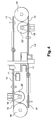
- a platform 9 unites the plates 7 and 8 between them on the side of the shoulder joint 4, and two motors 10 and 10 ' are mounted on that one. They have trees 11 and 11 'which extend on the second plate 8 up to belt transmission mechanisms 12 and 12 'which extend beyond the second plate 8 to nuts 13 and 13 'that the belts rotate. of the screws 14 and 14 'are threaded into the nuts 13 and 13 'and extend between the two plates 7 and 8 in the length direction of segment 1, as trees 11 and 11 '.
- the screws 14 and 14 ' form loops with cables 15 and 15 'stretched between driven pulleys 16 and 16 ', opposed pulleys 17 and 17 'and pairs of return pulleys 19, 20 and 19', 20 '.
- the cable 15 or 15 ' passes successively from one end of the screw 14 or 14 ', by the opposite pulley 17 or 17', the deflection pulley 19 or 19 ', driven pulley 16 or 16' and the return pulley 20 or 20 'before joining the opposite end of the screw 14 or 14 '.
- the pulleys 17 and 19 (or 17 'and 19'), it forms a strand substantially parallel to the screw 14 or 14 'and extending in front of the second plate 8, near the trees 11 and 11 ' and extends through the transmission 12 or 12 'without the to touch ; the return pulley 19 or 19 'maintains the cable 15 or 15 'in the plane of the driven pulley 16 or 16 ', and the return pulley 20 or 20' returns the cable 15 or 15 'in the alignment of the screw 14 or 14'.
- the driven pulleys 16 and 16 ' are double grooved and receive respective ends of the cable 15 or 15 ', which is cut.
- the ends of the cables 15 and 15 ' are tied in the throats. This provision, possible for pulleys that rotate only one turn portion, avoids any slipping of the cable and is a frequent job.
- Plates 7 and 8 carry pairs of lights 21, 21 'and 22, 22' which are grooves aligning in the direction of the screws 14 and 14 'and extending on both sides of them.
- the screws 14 and 14 'carry a carriage 23 or 23' from where exceed transverse axes 24 and 24 'carrying rollers 25 and 26, or 25 'and 26', who engage in rolling in the lights 21, 22, 21 'and 22'.
- This system ensures the rotational stop of the screws 14 and 14 'and therefore the good operation of the linear cylinder with conversion of movement. As the lights are operated directly in plates 7 and 8 needed to materialize segment 1, a gain in size and weight substantial is obtained.
- the support can then be rendered indented or hollow to eliminate the risk of contact, what we did here for the nut 13 or 13 'and the transmission 12 or 12 '; it is also possible to to deport the motor 10 or 10 'at the end of the segment 1, beyond the shoulder joint 4 here, which is favorable since the tipping movement they produce is diminished and that they can even contribute to a static balancing of the segment 1.
Landscapes
- Engineering & Computer Science (AREA)
- Robotics (AREA)
- Mechanical Engineering (AREA)
- Lining And Supports For Tunnels (AREA)
- Manipulator (AREA)
- Transmission Devices (AREA)
- Structures Of Non-Positive Displacement Pumps (AREA)
Abstract
Description
- la figure 1 illustre une réalisation du segment,
- la figure 2 un détail des parties essentielles (pour cette invention) du segment,
- la figure 3 une vue générale du segment et des éléments voisins, et
- la figure 4 une vue du mécanisme des vérins.
Claims (6)
- Segment (1) de structure articulée comprenant un support (7, 8) menant à deux éléments adjacents (2, 3) de la structure articulée, au moins un vérin placé sur le support et comprenant un moteur (10), un écrou (13), une vis (14) engagée dans l'écrou, et un organe d'arrêt en rotation (23) comprenant des galets (24) roulant sur des pistes, l'un de la vis et de l'écrou étant entraíné en rotation par le moteur et l'autre de la vis et de l'écrou portant les galets, caractérisé en ce que les pistes sont ménagées dans une rainure (21, 22) opérée dans le support.
- Segment de structure articulée selon la revendication 1, caractérisé en ce que le support comprend une plaque à travers laquelle la rainure est opérée.
- Segment de structure articulée selon la revendication 2, caractérisé en ce que l'écrou et la vis sont disposés d'un côté de la plaque, un organe d'entraínement en rotation (11) mû par le moteur (10) est disposé de l'autre côté de la plaque, et une transmission (12) s'étendant entre ledit organe d'entraínement et celui de la vis et de l'écrou qui est entraíné en rotation par le moteur traverse la plaque.
- Segment de structure articulé selon la revendication 2 ou 3, caractérisé en ce que le support comprend une seconde plaque, à travers laquelle une seconde rainure est opérée, la seconde rainure recevant certains des galets, la vis et l'écrou étant logés entre les plaques.
- Segment de structure articulée selon la revendication 3, caractérisé en ce que l'organe d'entraínement en rotation (11) mû par le moteur (10) a une longueur permettant de placer l'écrou à mi-longueur de la vis.
- Segment de structure articulé selon la revendication 3, caractérisé en ce qu'il comprend un second vérin placé sur le support et comprenant aussi un moteur (10), un écrou (13), une vis (14) engagée dans l'écrou, et un organe d'arrêt en rotation (23) comprenant des galets (24) roulant sur des pistes, l'un de la vis et de l'écrou étant entraíné en rotation par le moteur et l'autre de la vis et de l'écrou portant les galets, et où les pistes sont ménagées dans une rainure (21, 22) opérée dans le support ; dans le second vérin, l'écrou et la vis sont disposés d'un côté de la plaque, un organe d'entraínement en rotation (11) mû par le moteur (10) est disposé de l'autre côté de la plaque, et une transmission (12) s'étendant entre ledit organe d'entraínement et celui de la vis et de l'écrou qui est entraíné en rotation par le moteur traverse la plaque ; et les moteurs sont placés du même côté de la plaque.
Applications Claiming Priority (2)
| Application Number | Priority Date | Filing Date | Title |
|---|---|---|---|
| FR0350413A FR2858669B1 (fr) | 2003-08-08 | 2003-08-08 | Segment de structure articulee |
| FR0350413 | 2003-08-08 |
Publications (2)
| Publication Number | Publication Date |
|---|---|
| EP1504856A1 true EP1504856A1 (fr) | 2005-02-09 |
| EP1504856B1 EP1504856B1 (fr) | 2011-04-27 |
Family
ID=33548348
Family Applications (1)
| Application Number | Title | Priority Date | Filing Date |
|---|---|---|---|
| EP04103818A Expired - Lifetime EP1504856B1 (fr) | 2003-08-08 | 2004-08-06 | Segment de structure articulée comprenant un vérin linéaire à conversion de mouvement par vis et écrou |
Country Status (4)
| Country | Link |
|---|---|
| EP (1) | EP1504856B1 (fr) |
| AT (1) | ATE507035T1 (fr) |
| DE (1) | DE602004032410D1 (fr) |
| FR (1) | FR2858669B1 (fr) |
Cited By (3)
| Publication number | Priority date | Publication date | Assignee | Title |
|---|---|---|---|---|
| FR2949451A1 (fr) * | 2009-09-02 | 2011-03-04 | Commissariat Energie Atomique | Verin a cable et dispositif d'assistance aux personnes integrant un tel verin |
| FR2961424A1 (fr) * | 2010-06-21 | 2011-12-23 | Commissariat Energie Atomique | Segment de bras mecanique a longueur variable et bras mecanique comprenant ce segment |
| CN109209792A (zh) * | 2018-09-30 | 2019-01-15 | 华中科技大学 | 一种基于双向滚珠丝杠传动的膝关节发电装置及其应用 |
Citations (5)
| Publication number | Priority date | Publication date | Assignee | Title |
|---|---|---|---|---|
| EP0072786A2 (fr) * | 1981-08-17 | 1983-02-23 | IGM - Industriegeräte- und Maschinenfabriks-gesellschaft mbH | Réducteur de vitesse |
| JPS61192486A (ja) * | 1985-02-19 | 1986-08-27 | 株式会社神戸製鋼所 | 多関節型ア−ム装置 |
| JPH1137154A (ja) * | 1997-07-24 | 1999-02-09 | Oki Electric Ind Co Ltd | 直線ガイド機構 |
| FR2807959A1 (fr) * | 2000-04-21 | 2001-10-26 | Centre Nat Rech Scient | Actionneur concu pour des structures articulees, telles que des membres de robot marcheur |
| FR2809464A1 (fr) * | 2000-05-26 | 2001-11-30 | Commissariat Energie Atomique | Transmission a vis, ecrou et cable attache a la vis |
-
2003
- 2003-08-08 FR FR0350413A patent/FR2858669B1/fr not_active Expired - Fee Related
-
2004
- 2004-08-06 EP EP04103818A patent/EP1504856B1/fr not_active Expired - Lifetime
- 2004-08-06 AT AT04103818T patent/ATE507035T1/de not_active IP Right Cessation
- 2004-08-06 DE DE602004032410T patent/DE602004032410D1/de not_active Expired - Lifetime
Patent Citations (5)
| Publication number | Priority date | Publication date | Assignee | Title |
|---|---|---|---|---|
| EP0072786A2 (fr) * | 1981-08-17 | 1983-02-23 | IGM - Industriegeräte- und Maschinenfabriks-gesellschaft mbH | Réducteur de vitesse |
| JPS61192486A (ja) * | 1985-02-19 | 1986-08-27 | 株式会社神戸製鋼所 | 多関節型ア−ム装置 |
| JPH1137154A (ja) * | 1997-07-24 | 1999-02-09 | Oki Electric Ind Co Ltd | 直線ガイド機構 |
| FR2807959A1 (fr) * | 2000-04-21 | 2001-10-26 | Centre Nat Rech Scient | Actionneur concu pour des structures articulees, telles que des membres de robot marcheur |
| FR2809464A1 (fr) * | 2000-05-26 | 2001-11-30 | Commissariat Energie Atomique | Transmission a vis, ecrou et cable attache a la vis |
Non-Patent Citations (1)
| Title |
|---|
| PATENT ABSTRACTS OF JAPAN vol. 1999, no. 05 31 May 1999 (1999-05-31) * |
Cited By (4)
| Publication number | Priority date | Publication date | Assignee | Title |
|---|---|---|---|---|
| FR2949451A1 (fr) * | 2009-09-02 | 2011-03-04 | Commissariat Energie Atomique | Verin a cable et dispositif d'assistance aux personnes integrant un tel verin |
| WO2011026621A1 (fr) * | 2009-09-02 | 2011-03-10 | Commissariat A L'energie Atomique Et Aux Energies Alternatives | Verin a cable et dispositif d'assistance aux personnes integrant un tel verin |
| FR2961424A1 (fr) * | 2010-06-21 | 2011-12-23 | Commissariat Energie Atomique | Segment de bras mecanique a longueur variable et bras mecanique comprenant ce segment |
| CN109209792A (zh) * | 2018-09-30 | 2019-01-15 | 华中科技大学 | 一种基于双向滚珠丝杠传动的膝关节发电装置及其应用 |
Also Published As
| Publication number | Publication date |
|---|---|
| DE602004032410D1 (de) | 2011-06-09 |
| EP1504856B1 (fr) | 2011-04-27 |
| FR2858669A1 (fr) | 2005-02-11 |
| ATE507035T1 (de) | 2011-05-15 |
| FR2858669B1 (fr) | 2006-11-03 |
Similar Documents
| Publication | Publication Date | Title |
|---|---|---|
| EP0008981B1 (fr) | Manipulateur motorisé | |
| EP2582494B1 (fr) | Systeme d'actionnement avec reducteur a grand rapport de reduction, robot et interface haptique comportant au moins un tel systeme | |
| EP2164432B1 (fr) | Mecanisme de rotation d'avant-bras et orthese comportant un tel mecanisme | |
| FR2467060A1 (fr) | Robot industriel du type articule | |
| WO2014009192A1 (fr) | Dispositif de transmission de mouvement a reducteur epicycloidal, reducteur epicycloidal et bras de manipulation | |
| FR2832345A1 (fr) | Mecanisme articule comprenant un reducteur a cable utilisable dans un bras de robot | |
| WO2001081791A1 (fr) | Actionneur conçu pour des structures articulées, telles que des membres de robot marcheur | |
| CA2307291A1 (fr) | Element de liaison a verin a vis et ecrou et son application un bras de robot | |
| FR2833367A1 (fr) | Organe de commande a cables tendus | |
| FR2593106A1 (fr) | Dispositif de deplacement d'un outil ou analogue en porte-a-faux, notamment autour d'un objet. | |
| EP1504856B1 (fr) | Segment de structure articulée comprenant un vérin linéaire à conversion de mouvement par vis et écrou | |
| FR2543470A1 (fr) | Installation de transfert a mecanisme asservi de commande de la rotation des pinces de transfert | |
| FR2767174A1 (fr) | Dispositif de transformation de deux mouvements alternatifs en mouvement de rotation | |
| FR2493948A1 (fr) | Variateur impulsionnel | |
| FR2696365A1 (fr) | Mécanisme d'avance pour un laminoir à pas de pèlerin froid. | |
| FR2853273A1 (fr) | Dispositif d'actionnement, notamment pour un bras articule | |
| WO2019120760A1 (fr) | Actionneur reversible a deux axes non synchonises avec un seul moteur | |
| EP0473484A1 (fr) | Machine pour la rééducation d'une articulation d'un membre humain, en particulier du genou | |
| FR2753925A1 (fr) | Articulation oblique de robot | |
| EP0063792B1 (fr) | Dispositif d'entraînement, en un mouvement progressif bilatéral, d'un organe guidé sur des rails rectilignes | |
| FR2637250A1 (fr) | Variateur de vitesse pour cycle | |
| FR2863534A1 (fr) | Articulation de bras mecanique et bras pourvu de cette articulation | |
| FR2950830A1 (fr) | Structure de robot ou d'interface haptique a bras en paralleles | |
| FR2853272A1 (fr) | Bras articule comprenant des transmissions a cable | |
| FR3033310A1 (fr) | Entrainement pour bicyclette |
Legal Events
| Date | Code | Title | Description |
|---|---|---|---|
| PUAI | Public reference made under article 153(3) epc to a published international application that has entered the european phase |
Free format text: ORIGINAL CODE: 0009012 |
|
| AK | Designated contracting states |
Kind code of ref document: A1 Designated state(s): AT BE BG CH CY CZ DE DK EE ES FI FR GB GR HU IE IT LI LU MC NL PL PT RO SE SI SK TR |
|
| AX | Request for extension of the european patent |
Extension state: AL HR LT LV MK |
|
| 17P | Request for examination filed |
Effective date: 20050809 |
|
| AKX | Designation fees paid |
Designated state(s): AT BE BG CH CY CZ DE DK EE ES FI FR GB GR HU IE IT LI LU MC NL PL PT RO SE SI SK TR |
|
| RAP1 | Party data changed (applicant data changed or rights of an application transferred) |
Owner name: COMMISSARIAT A L'ENERGIE ATOMIQUE |
|
| RAP1 | Party data changed (applicant data changed or rights of an application transferred) |
Owner name: COMMISSARIAT A L'ENERGIE ATOMIQUE ET AUX ENERGIES |
|
| 17Q | First examination report despatched |
Effective date: 20100818 |
|
| GRAP | Despatch of communication of intention to grant a patent |
Free format text: ORIGINAL CODE: EPIDOSNIGR1 |
|
| GRAS | Grant fee paid |
Free format text: ORIGINAL CODE: EPIDOSNIGR3 |
|
| GRAA | (expected) grant |
Free format text: ORIGINAL CODE: 0009210 |
|
| AK | Designated contracting states |
Kind code of ref document: B1 Designated state(s): AT BE BG CH CY CZ DE DK EE ES FI FR GB GR HU IE IT LI LU MC NL PL PT RO SE SI SK TR |
|
| REG | Reference to a national code |
Ref country code: GB Ref legal event code: FG4D Free format text: NOT ENGLISH |
|
| REG | Reference to a national code |
Ref country code: CH Ref legal event code: EP |
|
| REG | Reference to a national code |
Ref country code: IE Ref legal event code: FG4D Free format text: LANGUAGE OF EP DOCUMENT: FRENCH |
|
| REF | Corresponds to: |
Ref document number: 602004032410 Country of ref document: DE Date of ref document: 20110609 Kind code of ref document: P |
|
| REG | Reference to a national code |
Ref country code: DE Ref legal event code: R096 Ref document number: 602004032410 Country of ref document: DE Effective date: 20110609 |
|
| REG | Reference to a national code |
Ref country code: NL Ref legal event code: VDEP Effective date: 20110427 |
|
| PG25 | Lapsed in a contracting state [announced via postgrant information from national office to epo] |
Ref country code: PT Free format text: LAPSE BECAUSE OF FAILURE TO SUBMIT A TRANSLATION OF THE DESCRIPTION OR TO PAY THE FEE WITHIN THE PRESCRIBED TIME-LIMIT Effective date: 20110829 Ref country code: SE Free format text: LAPSE BECAUSE OF FAILURE TO SUBMIT A TRANSLATION OF THE DESCRIPTION OR TO PAY THE FEE WITHIN THE PRESCRIBED TIME-LIMIT Effective date: 20110427 |
|
| REG | Reference to a national code |
Ref country code: IE Ref legal event code: FD4D |
|
| PG25 | Lapsed in a contracting state [announced via postgrant information from national office to epo] |
Ref country code: GR Free format text: LAPSE BECAUSE OF FAILURE TO SUBMIT A TRANSLATION OF THE DESCRIPTION OR TO PAY THE FEE WITHIN THE PRESCRIBED TIME-LIMIT Effective date: 20110728 Ref country code: CY Free format text: LAPSE BECAUSE OF FAILURE TO SUBMIT A TRANSLATION OF THE DESCRIPTION OR TO PAY THE FEE WITHIN THE PRESCRIBED TIME-LIMIT Effective date: 20110427 Ref country code: SI Free format text: LAPSE BECAUSE OF FAILURE TO SUBMIT A TRANSLATION OF THE DESCRIPTION OR TO PAY THE FEE WITHIN THE PRESCRIBED TIME-LIMIT Effective date: 20110427 Ref country code: AT Free format text: LAPSE BECAUSE OF FAILURE TO SUBMIT A TRANSLATION OF THE DESCRIPTION OR TO PAY THE FEE WITHIN THE PRESCRIBED TIME-LIMIT Effective date: 20110427 Ref country code: FI Free format text: LAPSE BECAUSE OF FAILURE TO SUBMIT A TRANSLATION OF THE DESCRIPTION OR TO PAY THE FEE WITHIN THE PRESCRIBED TIME-LIMIT Effective date: 20110427 Ref country code: ES Free format text: LAPSE BECAUSE OF FAILURE TO SUBMIT A TRANSLATION OF THE DESCRIPTION OR TO PAY THE FEE WITHIN THE PRESCRIBED TIME-LIMIT Effective date: 20110807 |
|
| PG25 | Lapsed in a contracting state [announced via postgrant information from national office to epo] |
Ref country code: NL Free format text: LAPSE BECAUSE OF FAILURE TO SUBMIT A TRANSLATION OF THE DESCRIPTION OR TO PAY THE FEE WITHIN THE PRESCRIBED TIME-LIMIT Effective date: 20110427 |
|
| PG25 | Lapsed in a contracting state [announced via postgrant information from national office to epo] |
Ref country code: EE Free format text: LAPSE BECAUSE OF FAILURE TO SUBMIT A TRANSLATION OF THE DESCRIPTION OR TO PAY THE FEE WITHIN THE PRESCRIBED TIME-LIMIT Effective date: 20110427 Ref country code: CZ Free format text: LAPSE BECAUSE OF FAILURE TO SUBMIT A TRANSLATION OF THE DESCRIPTION OR TO PAY THE FEE WITHIN THE PRESCRIBED TIME-LIMIT Effective date: 20110427 Ref country code: IE Free format text: LAPSE BECAUSE OF FAILURE TO SUBMIT A TRANSLATION OF THE DESCRIPTION OR TO PAY THE FEE WITHIN THE PRESCRIBED TIME-LIMIT Effective date: 20110427 |
|
| BERE | Be: lapsed |
Owner name: COMMISSARIAT A L'ENERGIE ATOMIQUE ET AUX ENERGIES Effective date: 20110831 |
|
| PG25 | Lapsed in a contracting state [announced via postgrant information from national office to epo] |
Ref country code: RO Free format text: LAPSE BECAUSE OF FAILURE TO SUBMIT A TRANSLATION OF THE DESCRIPTION OR TO PAY THE FEE WITHIN THE PRESCRIBED TIME-LIMIT Effective date: 20110427 Ref country code: DK Free format text: LAPSE BECAUSE OF FAILURE TO SUBMIT A TRANSLATION OF THE DESCRIPTION OR TO PAY THE FEE WITHIN THE PRESCRIBED TIME-LIMIT Effective date: 20110427 Ref country code: SK Free format text: LAPSE BECAUSE OF FAILURE TO SUBMIT A TRANSLATION OF THE DESCRIPTION OR TO PAY THE FEE WITHIN THE PRESCRIBED TIME-LIMIT Effective date: 20110427 Ref country code: PL Free format text: LAPSE BECAUSE OF FAILURE TO SUBMIT A TRANSLATION OF THE DESCRIPTION OR TO PAY THE FEE WITHIN THE PRESCRIBED TIME-LIMIT Effective date: 20110427 |
|
| PLBE | No opposition filed within time limit |
Free format text: ORIGINAL CODE: 0009261 |
|
| STAA | Information on the status of an ep patent application or granted ep patent |
Free format text: STATUS: NO OPPOSITION FILED WITHIN TIME LIMIT |
|
| PG25 | Lapsed in a contracting state [announced via postgrant information from national office to epo] |
Ref country code: MC Free format text: LAPSE BECAUSE OF NON-PAYMENT OF DUE FEES Effective date: 20110831 |
|
| REG | Reference to a national code |
Ref country code: CH Ref legal event code: PL |
|
| 26N | No opposition filed |
Effective date: 20120130 |
|
| PG25 | Lapsed in a contracting state [announced via postgrant information from national office to epo] |
Ref country code: LI Free format text: LAPSE BECAUSE OF NON-PAYMENT OF DUE FEES Effective date: 20110831 Ref country code: CH Free format text: LAPSE BECAUSE OF NON-PAYMENT OF DUE FEES Effective date: 20110831 |
|
| REG | Reference to a national code |
Ref country code: DE Ref legal event code: R097 Ref document number: 602004032410 Country of ref document: DE Effective date: 20120130 |
|
| PG25 | Lapsed in a contracting state [announced via postgrant information from national office to epo] |
Ref country code: IT Free format text: LAPSE BECAUSE OF FAILURE TO SUBMIT A TRANSLATION OF THE DESCRIPTION OR TO PAY THE FEE WITHIN THE PRESCRIBED TIME-LIMIT Effective date: 20110427 Ref country code: BE Free format text: LAPSE BECAUSE OF NON-PAYMENT OF DUE FEES Effective date: 20110831 |
|
| PG25 | Lapsed in a contracting state [announced via postgrant information from national office to epo] |
Ref country code: LU Free format text: LAPSE BECAUSE OF NON-PAYMENT OF DUE FEES Effective date: 20110806 |
|
| PG25 | Lapsed in a contracting state [announced via postgrant information from national office to epo] |
Ref country code: BG Free format text: LAPSE BECAUSE OF FAILURE TO SUBMIT A TRANSLATION OF THE DESCRIPTION OR TO PAY THE FEE WITHIN THE PRESCRIBED TIME-LIMIT Effective date: 20110727 |
|
| PG25 | Lapsed in a contracting state [announced via postgrant information from national office to epo] |
Ref country code: TR Free format text: LAPSE BECAUSE OF FAILURE TO SUBMIT A TRANSLATION OF THE DESCRIPTION OR TO PAY THE FEE WITHIN THE PRESCRIBED TIME-LIMIT Effective date: 20110427 |
|
| PG25 | Lapsed in a contracting state [announced via postgrant information from national office to epo] |
Ref country code: HU Free format text: LAPSE BECAUSE OF FAILURE TO SUBMIT A TRANSLATION OF THE DESCRIPTION OR TO PAY THE FEE WITHIN THE PRESCRIBED TIME-LIMIT Effective date: 20110427 |
|
| REG | Reference to a national code |
Ref country code: FR Ref legal event code: PLFP Year of fee payment: 13 |
|
| REG | Reference to a national code |
Ref country code: FR Ref legal event code: PLFP Year of fee payment: 14 |
|
| REG | Reference to a national code |
Ref country code: FR Ref legal event code: PLFP Year of fee payment: 15 |
|
| PGFP | Annual fee paid to national office [announced via postgrant information from national office to epo] |
Ref country code: GB Payment date: 20230824 Year of fee payment: 20 |
|
| PGFP | Annual fee paid to national office [announced via postgrant information from national office to epo] |
Ref country code: FR Payment date: 20230822 Year of fee payment: 20 Ref country code: DE Payment date: 20230822 Year of fee payment: 20 |
|
| REG | Reference to a national code |
Ref country code: DE Ref legal event code: R071 Ref document number: 602004032410 Country of ref document: DE |
|
| REG | Reference to a national code |
Ref country code: GB Ref legal event code: PE20 Expiry date: 20240805 |
|
| PG25 | Lapsed in a contracting state [announced via postgrant information from national office to epo] |
Ref country code: GB Free format text: LAPSE BECAUSE OF EXPIRATION OF PROTECTION Effective date: 20240805 |
|
| PG25 | Lapsed in a contracting state [announced via postgrant information from national office to epo] |
Ref country code: GB Free format text: LAPSE BECAUSE OF EXPIRATION OF PROTECTION Effective date: 20240805 |