EP1503330A1 - Method of detecting biological pattern, biological pattern detector, method of biological certificate and biological certificate apparatus - Google Patents
Method of detecting biological pattern, biological pattern detector, method of biological certificate and biological certificate apparatus Download PDFInfo
- Publication number
- EP1503330A1 EP1503330A1 EP03721050A EP03721050A EP1503330A1 EP 1503330 A1 EP1503330 A1 EP 1503330A1 EP 03721050 A EP03721050 A EP 03721050A EP 03721050 A EP03721050 A EP 03721050A EP 1503330 A1 EP1503330 A1 EP 1503330A1
- Authority
- EP
- European Patent Office
- Prior art keywords
- tissue
- pattern
- detecting
- light
- detected
- Prior art date
- Legal status (The legal status is an assumption and is not a legal conclusion. Google has not performed a legal analysis and makes no representation as to the accuracy of the status listed.)
- Granted
Links
Images


Classifications
-
- A—HUMAN NECESSITIES
- A61—MEDICAL OR VETERINARY SCIENCE; HYGIENE
- A61B—DIAGNOSIS; SURGERY; IDENTIFICATION
- A61B5/00—Measuring for diagnostic purposes; Identification of persons
- A61B5/117—Identification of persons
-
- G—PHYSICS
- G06—COMPUTING; CALCULATING OR COUNTING
- G06T—IMAGE DATA PROCESSING OR GENERATION, IN GENERAL
- G06T7/00—Image analysis
- G06T7/0002—Inspection of images, e.g. flaw detection
- G06T7/0012—Biomedical image inspection
-
- G—PHYSICS
- G01—MEASURING; TESTING
- G01N—INVESTIGATING OR ANALYSING MATERIALS BY DETERMINING THEIR CHEMICAL OR PHYSICAL PROPERTIES
- G01N21/00—Investigating or analysing materials by the use of optical means, i.e. using sub-millimetre waves, infrared, visible or ultraviolet light
- G01N21/17—Systems in which incident light is modified in accordance with the properties of the material investigated
- G01N21/47—Scattering, i.e. diffuse reflection
- G01N21/49—Scattering, i.e. diffuse reflection within a body or fluid
-
- G—PHYSICS
- G06—COMPUTING; CALCULATING OR COUNTING
- G06T—IMAGE DATA PROCESSING OR GENERATION, IN GENERAL
- G06T7/00—Image analysis
- G06T7/40—Analysis of texture
- G06T7/41—Analysis of texture based on statistical description of texture
- G06T7/42—Analysis of texture based on statistical description of texture using transform domain methods
-
- G—PHYSICS
- G06—COMPUTING; CALCULATING OR COUNTING
- G06V—IMAGE OR VIDEO RECOGNITION OR UNDERSTANDING
- G06V40/00—Recognition of biometric, human-related or animal-related patterns in image or video data
- G06V40/10—Human or animal bodies, e.g. vehicle occupants or pedestrians; Body parts, e.g. hands
- G06V40/12—Fingerprints or palmprints
- G06V40/1347—Preprocessing; Feature extraction
-
- G—PHYSICS
- G06—COMPUTING; CALCULATING OR COUNTING
- G06V—IMAGE OR VIDEO RECOGNITION OR UNDERSTANDING
- G06V40/00—Recognition of biometric, human-related or animal-related patterns in image or video data
- G06V40/10—Human or animal bodies, e.g. vehicle occupants or pedestrians; Body parts, e.g. hands
- G06V40/12—Fingerprints or palmprints
- G06V40/1365—Matching; Classification
-
- G—PHYSICS
- G06—COMPUTING; CALCULATING OR COUNTING
- G06V—IMAGE OR VIDEO RECOGNITION OR UNDERSTANDING
- G06V40/00—Recognition of biometric, human-related or animal-related patterns in image or video data
- G06V40/10—Human or animal bodies, e.g. vehicle occupants or pedestrians; Body parts, e.g. hands
- G06V40/12—Fingerprints or palmprints
- G06V40/1382—Detecting the live character of the finger, i.e. distinguishing from a fake or cadaver finger
- G06V40/1388—Detecting the live character of the finger, i.e. distinguishing from a fake or cadaver finger using image processing
-
- G—PHYSICS
- G06—COMPUTING; CALCULATING OR COUNTING
- G06V—IMAGE OR VIDEO RECOGNITION OR UNDERSTANDING
- G06V40/00—Recognition of biometric, human-related or animal-related patterns in image or video data
- G06V40/10—Human or animal bodies, e.g. vehicle occupants or pedestrians; Body parts, e.g. hands
- G06V40/12—Fingerprints or palmprints
- G06V40/1382—Detecting the live character of the finger, i.e. distinguishing from a fake or cadaver finger
- G06V40/1394—Detecting the live character of the finger, i.e. distinguishing from a fake or cadaver finger using acquisition arrangements
-
- G—PHYSICS
- G06—COMPUTING; CALCULATING OR COUNTING
- G06V—IMAGE OR VIDEO RECOGNITION OR UNDERSTANDING
- G06V40/00—Recognition of biometric, human-related or animal-related patterns in image or video data
- G06V40/10—Human or animal bodies, e.g. vehicle occupants or pedestrians; Body parts, e.g. hands
- G06V40/14—Vascular patterns
- G06V40/145—Sensors therefor
-
- G—PHYSICS
- G06—COMPUTING; CALCULATING OR COUNTING
- G06T—IMAGE DATA PROCESSING OR GENERATION, IN GENERAL
- G06T2207/00—Indexing scheme for image analysis or image enhancement
- G06T2207/30—Subject of image; Context of image processing
- G06T2207/30004—Biomedical image processing
- G06T2207/30088—Skin; Dermal
-
- G—PHYSICS
- G06—COMPUTING; CALCULATING OR COUNTING
- G06T—IMAGE DATA PROCESSING OR GENERATION, IN GENERAL
- G06T2207/00—Indexing scheme for image analysis or image enhancement
- G06T2207/30—Subject of image; Context of image processing
- G06T2207/30004—Biomedical image processing
- G06T2207/30101—Blood vessel; Artery; Vein; Vascular
-
- G—PHYSICS
- G06—COMPUTING; CALCULATING OR COUNTING
- G06V—IMAGE OR VIDEO RECOGNITION OR UNDERSTANDING
- G06V40/00—Recognition of biometric, human-related or animal-related patterns in image or video data
- G06V40/10—Human or animal bodies, e.g. vehicle occupants or pedestrians; Body parts, e.g. hands
- G06V40/12—Fingerprints or palmprints
- G06V40/1341—Sensing with light passing through the finger
-
- G—PHYSICS
- G06—COMPUTING; CALCULATING OR COUNTING
- G06V—IMAGE OR VIDEO RECOGNITION OR UNDERSTANDING
- G06V40/00—Recognition of biometric, human-related or animal-related patterns in image or video data
- G06V40/10—Human or animal bodies, e.g. vehicle occupants or pedestrians; Body parts, e.g. hands
- G06V40/14—Vascular patterns
Definitions
- the present invention relates to a new biometric pattern detecting method and biometric pattern detecting device for acquiring the pattern of a deep skin layer such as dermis or the like, and particularly to a biometric authentication method and a biometric authentication device.
- Fingerprints, palm patterns, or the like are widely used for person authentication. These patterns are skin ridge patterns wherein a part of the epidermal tissue is embedded in the roughness structure of the dermis, and accordingly, the patterns can be directly observed from the outside. That is to say, the aforementioned pattern essentially corresponds to the deep layer structure of the skin such as dermis or the like.
- the skin of the portion such as a palm, a sole, or the like, has a special structure wherein the epidermal structure corresponds to the structure of the dermis beneath the epidermal tissue, unlike the skin of other portions, leading to the physiological advantages such as high sensitivity of the touch sensory nerves of which ends are positioned in the deep layer of the skin to external stimulation, great toughness regarding friction, and so forth.
- the fingerprints have been used for person authentication since the fingerprints exhibit sufficient stability essentially due to the high stability of the deep layer structure therebeneath.
- the aforementioned biometric authentication using the fingerprints does not provide sufficient security against so-called "spoofing” or the like. That is to say, the fingerprints are readily left on various objects, and the fingerprints left on the object can be easily observed, leading to a risk that other persons would forge the fingerprints.
- the epidermal tissue of other portions avoids the aforementioned risk of forgery, for example.
- the epidermal tissue changes due to metabolism thereof in a 28-day cycle.
- the epidermal tissue readily exhibits various conditions due to rough skin, dry skin, or the like. Accordingly, the epidermal tissue of other portions does not have sufficient stability.
- the patterns of the epidermal tissue of the base portion of a finger, the thenar region, and the like do not correspond to the patterns thereunderneath at all, rather, in some cases, the patterns of the epidermal tissue thereof are formed orthogonal to the patterns thereunderneath, except for a special case such as the fingerprints, leading to difficulty in biometric authentication using such a portion.
- a large part of the epidermal tissue of the human body including the palm portion such as the thenar region and so forth, the base portion of a finger, the skin of the back of the hand, and the like, has patterns different from the patterns of the deep-layer structure therebeneath, except for a special case such as the fingerprints which are fingertip impressions, wherein the epidermal tissue directly corresponds to the deep-layer structure, allowing external observation thereof.
- the deep-layer structure beneath the epidermal tissue is essentially unique to an individual, and exhibits sufficient stability over time, as with a well-known example of fingerprints or the like.
- a tattoo wherein a pigment is injected into the deep-layer structure, and a stretch mark caused by pregnancy, also have the same stability due to the properties of the deep-layer structure beneath the epithelium tissue. Accordingly, it is expected that the pattern beneath the epithelium tissue, i.e., the deep-layer structure of the epithelium tissue is suitably used for biometric authentication.
- the aforementioned patterns cannot be directly observed, neither left on an object by contact with the object, and accordingly, development of the authentication device using the pattern of the deep-layer structure has not been made, although the pattern of the deep-layer structure has the same performance of biometric authentication as with fingerprints.
- the present invention has been made in order to solve the aforementioned problems, and accordingly, it is an object thereof to provide a biometric pattern detecting method and biometric pattern detecting device for acquiring the roughness structure distribution of the deep-layer structure beneath the epithelium tissue (patterns beneath the epithelium tissue) or the blood-vessel pattern beneath the epithelium tissue, which cannot be directly observed. Furthermore, it is an object of the present invention to provide a biometric authentication method and a biometric authentication device which enables stable biometric authentication while preventing a risk of "spoofing", e.g., forgery or the like.
- the present inventor has made various study in order to achieve the aforementioned object. As a result, it has become clear that discrimination can be made between epidermal tissue and deep-layer tissue of the skin using difference in properties (optical properties, electric properties, and temperature difference) therebetween, and the roughness distribution pattern of the deep-layer tissue of the skin wherein visual observation is difficult due to shielding with epidermis is clearly detected. Accordingly, it has become clear that the pattern of any desired portion of the skin and subcutaneous tissue over the entire body of the user can be detected, as well as a special portion where the epidermal pattern corresponds to the dermal pattern such as fingerprints or the like, and the pattern thus detected can be applied to biometric authentication (person authentication).
- biometric authentication person authentication
- a living-tissue pattern detecting method according to the present invention, the roughness distribution pattern of the deep-layer tissue of the skin covered with the epidermal tissue is detected using difference in properties (optical properties, electric properties, and temperature difference) therebetween, thereby extracting a unique pattern of the living tissue.
- a living-tissue pattern detecting device includes means for detecting the roughness distribution pattern of the deep-layer tissue of the skin covered with the epidermal tissue.
- a biometric authentication method the roughness distribution pattern of the deep-layer tissue of the skin covered with the epidermal tissue is detected so as to be compared to a pattern registered beforehand, whereby biometric authentication is performed.
- a biometric authentication device includes means for detecting the roughness distribution pattern of the deep-layer tissue of the skin covered with the epidermal tissue, and the pattern thus detected is compared to a pattern registered beforehand, whereby biometric authentication is performed.
- the present invention has been made based upon the basic concept that authentication is performed not using an epidermal pattern, but using the pattern of the deep-layer tissue of the skin, e.g., a dermal pattern.
- the roughness distribution pattern (pattern) of the deep-layer tissue is unique to individual living tissue as with fingerprints, palm pattern, sole pattern, and so forth, and exhibits small change over time, i.e., exhibits high stability.
- the deep-layer tissue of a large part of the skin has a different pattern from that of the epidermal layer, except for special portions such as a fingertip having fingerprints which can be observed from the outside, or the like.
- the pattern of the deep-layer tissue is covered with the epidermal tissue, leading to difficulty in visual observation from the outside. Furthermore, no impression is left on any object even if the tissue comes in contact with the object. Accordingly, it is almost impossible for other persons to forge such a pattern.
- the system does not detect the structure of dead tissue having no nucleus such as the horny layer of the skin, specifically, fingerprints, and so forth, but detects deep-layer tissue of the skin which is living tissue, as described above.
- the deep-layer tissue of the skin does not maintain the pattern thereof if the deep-layer tissue is cut off from the living human body.
- the deep-layer tissue of the skin has blood capillaries therein, and the pattern formed of the blood flow within the blood capillaries is unique to the living tissue.
- the aforementioned pattern is immediately lost due to contraction of blood vessels, retention of blood, lost of blood, and so forth. This affects the pattern of the entire deep-layer tissue of the skin.
- the biometric authentication and the living-tissue discrimination are integrated, thereby suppressing the risk of "spoofing" using the tissue of the user to an unrealistic level, and thereby realizing true "biometric authentication”.
- the aforementioned deep-layer tissue of the skin e.g., the roughness distribution pattern of dermal layer can be optically detected using the fact that difference in the structure between epidermal tissue formed of simple cells or dead cells thereof and dermal tissue which is dense connective tissue causes difference in scattering properties and refraction properties therebetween, and this leads to depolarization or difference in frequency between the incident light and the returning light.
- polarized light is cast onto the tissue, as well as detecting the reflected light through a polarizing filter with the polarizing plane orthogonal to that of the aforementioned polarized light, thereby detecting the aforementioned roughness distribution pattern.
- the polarized light is cast on the surface of the tissue, and the reflected light is filtered with the polarizing filter with the polarizing plane orthogonal to the aforementioned polarized light, and accordingly, only the depolarized light due to scattering in the living tissue, such as back-scattered light, light split due to birefringence, and so forth, is detected, thereby extracting the pattern of the tissue having the nature which causes scattering of light, such as a dermal layer beneath epidermis and so forth.
- an arrangement may be made wherein long-wavelength light such as near-infrared light and so forth, which has the nature that the light readily passes through the epidermal tissue, and is readily scattered in dermal tissue, is employed as the aforementioned polarized light, thereby reducing adverse effects due to absorption of the polarized light in the living tissue, and thereby effectively detecting the pattern of the subcutaneous tissue beneath epidermis due to desirable optical properties (scattering properties, birefringence properties, and so forth) of the subcutaneous tissue beneath epidermis.
- long-wavelength light such as near-infrared light and so forth, which has the nature that the light readily passes through the epidermal tissue, and is readily scattered in dermal tissue
- an arrangement may be made wherein the illumination light is case onto the tissue, as well as causing interference between a part of the illumination light and the reflected light so as to detect change in wavelength components of the reflected light in the form of an interference pattern, thereby extracting a unique pattern of the living tissue.
- the system causes interference between the reflected or scattered light from the skin and the incident light split by a half mirror or the like serving as reference light, thereby detecting change in wavelength components due to birefringence or scattering in the internal structure of the skin in the form of a beat pattern (interference pattern).
- a beat pattern has properties unique to an individual living tissue, thereby enabling authentication using the beat pattern.
- an arrangement may be made wherein the subcutaneous tissue structure covered with epidermal tissue is electrically detected using difference in electric properties between the epidermal tissue and the deep-layer tissue of the skin, and the subcutaneous tissue structure thus detected is compared to a pattern registered beforehand, thereby enabling biometric authentication. Furthermore, an arrangement may be made wherein the subcutaneous tissue structure covered with epidermal tissue is detected using difference in temperature between the epidermal tissue and the deep-layer tissue of the skin, and the subcutaneous tissue structure thus detected is compared to a pattern registered beforehand, thereby enabling biometric authentication.
- the biometric authentication using the fingerprints has a risk of forgery by other persons since the impressions (fingerprints) are readily left on another object, and can be easily observed.
- the biometric authentication using the fingerprints is essentially measurement wherein the tissue structure of the dead tissue having no nucleus such as the horny layer of the skin is optically or electrically detected.
- the security performance of the biometric authentication using the aforementioned fingerprints, the iris, or the like does not only depend upon the detection precision, but also the aforementioned living-tissue discrimination. For example, let us say that other persons can breach the living-tissue discrimination at the time of the biometric authentication using the fingerprints, as well as having obtained the tissue used for the biometric authentication. This allows the other persons to easily make "spoofing", resulting in deterioration in the security of the system to zero. Furthermore, the aforementioned "spoofing" using the tissue leads to a new additional risk of a serious hazard to the body and the life of the user, as well as the financial risk in a case wherein the security of the conventional credit card is breached. The aforementioned serious hazard to the body and the life of the user will be referred to as "surgical hazard" hereafter.
- the biometric authentication needs to provide not only the sufficient limitation security performance which has been proposed in the conventional authentication techniques, but also the sufficient security performance against the surgical hazard for securing the safety of the user, which has been hardly proposed in the conventional techniques.
- the security performance of the biometric authentication consists of two kinds of the security performance.
- One security performance depends upon the precision of the "authentication” for identifying whether or not that the tissue which is to be authenticated matches the tissue of the user.
- the other security performance depends upon the precision of the "living-tissue discrimination” for determining whether or not the tissue used for authentication is live tissue, i.e., for confirming that the tissue is not dead tissue cut off from the body of the user.
- the conventional biometric authentication techniques have provided only the precision and reliability of the former security performance.
- the "biometric authentication” used here essentially means authentication without "living-tissue discrimination", and accordingly, does not mean true biometric authentication. Accordingly, from the practical perspective, the conventional security system having such a problem may lead to the additional hazard, i.e., the surgical hazard.
- spoofing is made using the tissue such as a finger, arm, eyeball, or the like, which has been cut off from the body of the user.
- tissue such as a finger, arm, eyeball, or the like
- Such a simple method for breaching the biometric authentication security leads to a new additional and serious hazard to the life and body of the user, of which money cannot replace, even in a case of small finance loss.
- the conventional biometric authentication methods using the fingerprints, iris within the eyeball, or the like remain accessory means used with other main authentication means, or remain accessory means in a limited form for unimportant matter, or the like. This leads to difficulty in wide use of the conventional biometric authentication.
- forgery of the fingerprints or the like can be relatively easily made.
- electrostatic capacity or electrostatic induction is measured between the finger and the electrode so as to detect the distance between the surface of the skin and the electrode, thereby detecting the pattern of the fingerprints, using the fact that the surface of the skin serves as a conductive material due to moisture (water) containing salt from sweat or the like secreted from the live tissue.
- moisture water
- This is a kind of an example of the biometric authentication with the "living-tissue discrimination". The reason is that the aforementioned measurement is impossible without moisture which is an electrolyte containing salt from sweat or the like secreted from the live tissue.
- the aforementioned detecting method requires moisture serving as an electrolyte on the surface of the object which is to be authenticated, the aforementioned object does not need to be alive. That is to say, with the aforementioned detecting method, the "living-tissue discrimination" is not performed for confirming that the object which is to be authenticated has not been cut off from the body of the user, for example. Accordingly, with the aforementioned detecting method, it is difficult to reject unauthorized means such as forgery of the fingerprints formed of a gel material having water retentivity, or the finger which has been cut off from the body of the user and subjected to spraying with or soaking in a physiological salt solution.
- the biometric authentication using DNA does not include "living-tissue discrimination". Accordingly, the biometric authentication using DNA needs some sort of a countermeasure such as a new separate sensor for discriminating whether or not the sample belongs :to the live body of the user with a suitable method such as detection of the blood flow in the finger using infrared light and so forth, as well as "biometric authentication”.
- a countermeasure such as a new separate sensor for discriminating whether or not the sample belongs :to the live body of the user with a suitable method such as detection of the blood flow in the finger using infrared light and so forth, as well as "biometric authentication”.
- the "biometric authentication” is performed by two means. One is “authentication”, and the other is “living-tissue discrimination”. That is to say, the conventional "biometric authentication” does not only depend upon the "authentication” serving as a "front door” as if it were, but also "living-tissue discrimination” serving as a "back door” as if it were, which is performed in separate detection means using a different physical principle. Accordingly, the conventional "biometric authentication” has a problem that if other persons breach the security of the "living-tissue discrimination" serving as a back door, the security of the biometric authentication security is breached, leading to a risk of "spoofing", and further leading to a risk of surgical hazard.
- the system discriminates whether the tissue which is to be authenticated is alive or dead.
- the living tissue has great diversity, and accordingly, the "living-tissue discrimination” must be performed for a single tissue sample with a sufficiently wide threshold range, as can be understood from the standing theory (central dogma) what life is.
- biometric authentication is performed based upon the detected roughness distribution pattern of the epithelial deep-structure tissue, e.g., dermal layer, instead of patterns of the epidermal tissue such as fingerprints described above.
- Fig. 1 is a schematic diagram which shows skin tissue which is roughly classified into epidermis 1 and dermis 2.
- the epidermis 1 is keratinized stratified flattened epithelium formed of a horny layer 11, a lucid layer 12, a granular layer 13, a prickle layer 14, a basal layer 15, and a basement membrane 16.
- a layer formed of the granular layer 13, the prickle layer 14, a basal layer 15, is referred to as "Malpighian layer".
- the horny layer 11 has a lamellar liquid crystal structure formed of a bilayer membrane formed of a horny-layer intercellular lipid.
- the lucid layer 12 has a cholesteric liquid crystal structure, and the granular layer 13 is formed of cells of which cytoplasm contains basic structures which are referred to as "keratohyalin granule" having optical properties which cause reflection and scattering of light, like beads.
- the basal layer 15 has melanin granules.
- the skin tissue has a multi-layer structure having various optical scattering/absorption properties due to each layer, leading to the advantage of preventing the living tissue from exposure to ultraviolet light or the like.
- the epidermis 1 has a kind of dichroic properties for ultraviolet light due to the multi-layer structure formed of thin membranes each of which has a different refractive index.
- the epidermis 1 is translucent tissue having relatively high scattering properties in a range of visible light, except for absorption of the light due to the melanin pigment.
- the epidermis 1 has high transparency in a longer wavelength range than with red visible light or near-infrared light. Accordingly, the light reflected from the blood flow in the blood capillaries within the dermis 2 beneath the epidermis 1 is scattered. The scattered light is observed as a complexion or the color of the skin.
- the color of the skin essentially depends upon the distribution of the melanin pigment and the blood flow within the blood capillaries in the dermis 2.
- the flow of an electrolyte fluid such as blood or lymph does not occur in the epidermis 1, and accordingly, the epidermis 1 essentially serves as a dielectric as exemplified by the horny layer 11.
- the dermis 2 has essentially different structure as compared with the epidermis 1.
- the dermis 2 essentially comprises the dense fibrous connective tissue formed of collagen or elastin, and a blood capillary pattern, unlike the epidermis 1 formed of simple cells having no blood capillaries.
- the dermis 2 is classified into a papillary layer and a reticular layer.
- the dermal papillary layer is in contact with the epidermal tissue through the basement membrane serving as the lowermost layer of the epidermal tissue, is formed of the connective tissue and the blood capillary pattern, and has the end of the sensory nerve.
- the reticular layer is formed of collagen having an array structure, elastin for connecting the collagen structures one to another, and a matrix which fills the space therebetween.
- the dermis 2 contains a great amount of the electrolyte fluid due to great amount of blood capillaries and the flow of lymph or the like, leading to extremely high electric conductivity as compared with the epidermis 1.
- the epidermal tissue While the collagen and elastic fibrous tissue forming connecting tissue of the dermis 2 exhibits high optical birefringence, the epidermal tissue does not exhibit birefringence.
- the epidermis 1 has optical properties which cause scattering of light, and polarization properties which cause depolarization of light due to scattering thereof. In a basic mechanism, the tissue exhibits a unique vertical/horizontal polarization ratio dependent upon the size and shape of the scattering particles therewithin.
- the electromagnetic wave geometrically passes through the object. (e.g., rainbow formed of rain particles, diamond dusts)
- the dermis 2 having a thickness greater than a certain thickness appears white, like milk agar. Furthermore, the dermis 2 has optical properties wherein the longer the wavelength of light is, the more readily the light passes through the dermis 2. On the other hand, the shorter the wavelength of the light is, the more readily the light is scattered. Let us say that the dermis 2 contains a significant amount of absorption pigment. In this case, the short-wavelength light scattered at a shallow portion returns to the eyes of the observer with a high probability. However, the long-wavelength light returns to the observer with a low probability due to absorption of the light in the pigment.
- the blood capillaries at the shallow portion of the skin appear vivid red from external observation, and the vein and hemangioma positioned at relatively deep portion appears relatively blue.
- the nevus (birthmark) due to melanocyte which is positioned at the boundary between the dermis and the epidermis appears relatively brown from the external observation
- the blue nevus positioned in the dermis appears relatively blue from the external observation, wherein the name agrees with the color.
- the Ota's nevus and Mongolian spot due to dermal melanocyte appear relatively blue from the clinical observation.
- the system detects the roughness distribution pattern or the like of the deep structure of the skin (e.g., dermal tissue) using difference in optical properties or electric properties between the dermal tissue and the epidermal tissue, whereby biometric authentication is performed.
- the reflected light from the tissue sample is subjected to filtering so as to discriminate the dermal layer formed of the connecting tissue, collagen fibrous tissue, or the like, in a deeper portion, from the epidermal tissue, using the difference in the scattering/polarization properties of the reflected light as to the incident white light between the dermal tissue and the epidermal tissue.
- This enables the user to clearly discriminate the dermal tissue wherein observation is difficult due to shading by the epidermal tissue, from the epidermal tissue.
- the present invention has the advantage of enabling person authentication by detecting the pattern of the dermal tissue, even using the skin or the subcutaneous tissue of any portion of the body of the use, as well as a special portion such as fingerprints and so forth, where the dermal tissue pattern matches the epidermal tissue pattern.
- Fig. 2 shows an configuration example of a detecting device for acquiring an optical image of the dermis 2 beneath the epidermis having a great diversity of scattering mechanisms as described above.
- the detecting device has a configuration which allows the light returning due to scattering and birefringence to pass through the receiver of the detecting device while preventing the light reflected from the epidermal layer from being received, by polarizing means including polarizing plates at the light-emitting unit and the light-receiving unit with planes of polarization orthogonal one to another.
- an illuminating optical system includes a light source 21, optical lens 22, and an illumination-unit polarizing plate 23. Any suitable light source such as an LED or the like can be employed as the light source 21. Note that a light source for emitting long-wavelength light such as near-infrared light or the like is preferably employed as the light source 21 since such long-wavelength light has the nature to readily pass through the epidermal tissue, as well as being reflected by the dermal tissue. Such a configuration enables acquisition of the pattern of the tissue using the optical properties such as scattering properties, birefringence properties, and so forth.
- an imaging optical system includes an imaging device (solid-state image sensor, e.g., CCD) 24 serving as a light-receiving device, an imaging lens set 25, and a receiving-unit polarizing plate 26. Furthermore, a half mirror 27 is disposed on a light path between the aforementioned illuminating optical system and the imaging optical system. Note that the aforementioned illuminating optical system and the imaging optical system are disposed with the polarizing planes orthogonal one to another.
- an imaging device solid-state image sensor, e.g., CCD
- the illumination light is cast from the light source 21 onto the skin with a single polarizing plane determined by the illumination-unit polarizing plate 23.
- the imaging optical system includes the receiving-unit polarizing plate 26 with the polarizing plane orthogonal to that of the illumination-unit polarizing plate 23. Accordingly, the reflected light from the epidermal tissue through simple reflection passes through with a polarizing plane orthogonal to the polarizing plane of the receiving-unit polarizing plate 26, whereby such reflected light is intercepted by the receiving-unit polarizing plate 26.
- the illumination light cast onto the skin from the illumination optical system reaches the deep-layer tissue of the skin (e.g., dermal tissue), leading to scattering of the light or birefringence thereof due to various kinds of tissue, resulting in depolarization thereof.
- the reflected light e.g., back-scattered light
- the aforementioned scattered or reflected light exhibits phase shift as to the incident light due to birefringence thereof caused by reflection or scattering in the dermal tissue containing connecting tissue, collagen, and so forth, having properties which cause birefringence of the light.
- the epidermal tissue does not contain the aforementioned materials having properties which cause birefringence of the light.
- the system discriminates between the scattered/reflected light from the epidermal tissue and from the dermal tissue (which causes birefringence of the light) by detecting the difference in the phase of the light therebetween.
- an arrangement may be made wherein the system allows only the reflected light with a phase shift in a predetermined wavelength range due to birefringence in the dermal tissue, to pass through a band-pass filter such as a dichroic filter or the like, and detects only the light thus selected, thereby selectively detecting only the tissue which causes birefringence of the light, and thereby enabling external observation of the dermal tissue in a noninvasive manner.
- a band-pass filter such as a dichroic filter or the like
- a method is known in the field of the beauty industry, wherein the skin is observed with polarized light using the optical properties of a polarizing filter in a range of the visible light.
- a measurement method for evaluating the surface of the skin is known, wherein the beauty factors such as the glossiness of the skin, the brightness thereof, and so forth, are measured (see Japanese Examined Patent Application Publication No. 3,194,152, or Japanese Examined Utility Model Registration Application No. 7-22655).
- the disclosed arrangement is nothing but a method wherein an image of the skin is obtained from scattered light from the skin using visible light while preventing deterioration in image quality due to the excessive brightness of the reflected light directly reflected from the horny layer of the epidermis or the like, using the well-known nature that depolarization of the light occurs due to scattering, thereby obtaining a stable image of the skin.
- the aforementioned detecting device has a function for detecting the dermal-layer structure (e.g., the roughness distribution pattern) using the scattering properties or the birefringence properties of the dense connective tissue forming the dermal layer.
- the detecting device having a configuration as shown in Fig. 2 has the disadvantage of reduction of the SN ratio due to increased noise due to scattered light from the epidermal layer, and scattered light from the dermal tissue, subcutaneous tissue, and so forth, beneath the surface of the dermal layer which is to be detected.
- Fig. 3 shows an effective configuration example of the detecting device for solving the aforementioned problem, wherein the illumination light is cast onto the skin with a shallow angle, as well as limiting the aperture of the imaging optical system.
- the detecting device shown in Fig. 3 further includes a moving reflecting mirror 28, and has a configuration wherein the illumination is cast onto the skin in a slant direction from the illumination optical system. Furthermore, the detecting device includes the imaging optical system disposed just above the tissue which is to be measured, thereby enabling direct detection of the back-scattered light and side-scattered light without the half mirror 27. Furthermore, the detecting device includes a shield 29 for limiting the aperture, thereby allowing only the light returning from the portion just underneath the aperture, to reach the imaging device 24.
- the illumination light cast from the illumination optical system passes through the tissue toward the deep-layer structure of the skin (dermal layer) from the epidermal layer in a slant direction.
- scattering of light due to an excessively shallow portion i.e., the epidermal tissue, occurs in the region on the right side shown in the drawing, thereby preventing the scattered light from the excessively shallow portion from reaching the imaging optical system with the aperture limited by the shield 29.
- scattering of light due to an excessively deep portion occurs in the region on the left side shown in the drawing, thereby preventing the scattered light from the excessively deep portion from reaching the imaging optical system with the aperture limited by the shield 29.
- the detecting device wherein the angle of the aforementioned moving reflecting mirror 28 is adjusted such that the position of the dermal tissue onto which the incident light is cast, is positioned just underneath the aforementioned imaging optical system, only the scattered light from this region (dermal tissue) reaches the imaging optical system.
- an arrangement may be made using a well-known method for detecting the birefringence, e.g., using the optical heterodyne interferometry for converting the phase difference between the illumination light and the reflected light or transmitted light into the phase difference in the beat signals, instead of a method using a band-pass filter as described above.
- Fig. 4 is a diagram which shows a mechanism of such an arrangement.
- the detecting device has a configuration wherein the oscillating light is cast to a sample 33 from a light source, e.g., a Stabilized Transverse Zeeman Laser (STZL) 31 through a half mirror 32, and the transmitted light (signal light) passing through a polarizing plate 34 is detected with a photo-detector 35.
- a part of the oscillating light emitted from the Stabilized Transverse Zeeman Laser 31 is reflected by the half mirror 32, following which the reflected light (reference light) passes through a polarizing plate 36, whereby the reference light is detected with a photo-detector 37.
- the phase difference in the light detected by the aforementioned photo-detectors 35 and 37 is measured with an electronic phase meter 38.
- the linear polarizers (polarizing plates 34 and 36) are used for causing interference between two light waves. Note that this mechanism enables measurement of the birefringence of the light with precision determined by the electronic phase meter 38.
- the electronic phase meter 38 exhibits the measurement precision of 0.1 degree (or more), thereby enabling measurement of the birefringence of the light with high precision of approximately 1/4000 of the wavelength of the light.
- E r a r cos(2 ⁇ f r t + ⁇ r )
- E s a s cos(2 ⁇ f s t + ⁇ s )
- a r and a s represent the amplitude of the reference light and the amplitude of the signal light, respectively.
- f r and f s represent the frequency of the reference light and the frequency of the signal light, respectively
- ⁇ r and ⁇ s represent the phase of the reference light and the phase of the signal light, respectively.
- the light intensity I is represented by the square of the electric-field component, and accordingly, the light intensity I obtained by superimposing the two light waves is represented as follows.
- the reference symbol " ⁇ >" represents the average over time.
- the photoelectric current detected with the photo-detector is classified into the DC component represented by the first term and the second term of the Expression (3), and the AC component which changes in the shape of a sine wave with the frequency fb as represented by the third term thereof.
- the AC signal will be referred to as "optical-beat signal”.
- the amplitude of the optical-beat signal (2a s • a r ), the frequency (f b ), or the phase ( ⁇ ) is electrically measured, and the information is obtained based upon the amplitude (as) of the light signal, the frequency (f s ), or the phase ( ⁇ s ).
- the light having two frequency components slightly different one from another such as STZL (Stabilized Transverse Zeeman Laser) oscillating light or the like, is cast onto the sample.
- STZL Stabilized Transverse Zeeman Laser
- the light intensity signal I detected by the photo-detector is represented as follows.
- reference character " ⁇ ” represents the phase difference between the two components of the light
- the phase difference between the two light components is represented by the phase difference of the beat signals. This enables measurement of the magnitude of the birefringence by measuring the phase of the optical-beat signals with the electronic phase meter 38 or the like.
- the skin containing a fork structure of the subcutaneous blood vessel is used as the skin which is to be authenticated.
- the direction of the aforementioned principal axis can be easily obtained using the fork structure.
- an arrangement may be made wherein the positional relation between the direction of the principal axis and the fork structure is determined and stored beforehand at the time of user registration, thereby enabling adjustment of the principal axis at the time of user authentication based upon the position and the direction of the blood-vessel fork structure in a simple manner.
- the object of the present invention is not to provide measurement of the magnitude of the birefringence, but it is an object thereof to provide a detecting method for detecting the unique properties of the user by measuring the internal structure of the skin through birefringence of the light or scattering thereof.
- the system causes interference between the incident light and the scattered light from the skin without any polarizer, and obtains the change in the frequency therebetween in the form of beat signals by detecting the interference of the light, using the fact that upon casting the light onto the skin, the frequency of the light changes due to backscattering of the light or birefringence thereof occurring in the internal structure of the skin such as the dermal layer or the like.
- Fig. 5 shows a configuration example of such a detecting device.
- the detecting device has the same configuration as with the detecting device shown in Fig. 2 wherein an illumination optical system formed of an illumination light source 41 and an optical lens 42, and an imaging optical system formed of an imaging device 43 such as a CCD or the like and an imaging lens 44, are disposed orthogonal one to another through a half mirror 45.
- neither of the illumination optical system and the imaging optical system include a polarizing plate.
- the present detecting device includes a reference mirror 46 for introducing a part of the illumination light cast from the light source 41 of the illumination optical system to the imaging device 43 of the imaging optical system.
- a part of the light emitted from the light source 41 such as a white LED or the like is cast on the surface of the skin through the half mirror 45.
- various kinds of scattering of the light and birefringence thereof occur in the internal structure of the skin, and the scattered light returns to the half mirror 45.
- the system causes a beat phenomenon (interference) between the returning light and the light which is reflected from the half mirror 45 onto the reference mirror 46, and is reflected by the reference mirror 46, at the same time of illumination, whereby an interference pattern is formed on the imaging device 43.
- an arrangement may be made wherein the aforementioned beat is detected for each region in a detecting range for the skin, thereby obtaining a continuous pattern of the internal structure beneath the epidermis based upon the beat pattern thus obtained.
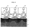
- Specific arrangement examples for obtaining the aforementioned continuos pattern include: an arrangement wherein multiple beat detecting devices are arrayed as shown in Fig. 6; and an arrangement wherein the illumination unit includes a moving mirror for casting the light onto each region of the skin as shown in Fig. 7.
- the former arrangement has a configuration wherein the multiple beat detecting devices 50 are arrayed in the shape of a so-called "array", each of which comprise the illumination optical system formed of the aforementioned illumination light source 41 and the optical lens 42, and the imaging optical system formed of the imaging device 43 such as a CCD or the like and the optical lens 44, disposed orthogonal one to another through the half mirror 45, thereby obtaining a continuos pattern of the internal structure beneath the epidermis based upon the signals detected with each beat detecting device 50.
- array each of which comprise the illumination optical system formed of the aforementioned illumination light source 41 and the optical lens 42, and the imaging optical system formed of the imaging device 43 such as a CCD or the like and the optical lens 44, disposed orthogonal one to another through the half mirror 45, thereby obtaining a continuos pattern of the internal structure beneath the epidermis based upon the signals detected with each beat detecting device 50.
- the latter arrangement has a configuration wherein a mirror control unit 52 controls the angle of the moving mirror 51 according to control information from an angle/interference-pattern adjusting unit 53.
- the aforementioned angle/interference-pattern adjusting unit 53 receives interference-pattern information from the aforementioned beat detecting device 50. Then, the received interference pattern is compared to an interference pattern which has been stored and registered beforehand in a skin-interference pattern storage unit 54, in a skin-interference pattern storage/comparison unit 55, thereby enabling biometric authentication.
- the aforementioned methods do not require a polarizer which is indispensable for detection of the phase difference or the like, thereby having the advantage of enabling authentication without precise adjustment of the optical axis. This allows stable authentication even if the direction of a wristwatch-type authentication device or the like, fit by the user, changes due to failure in being fit by the user, looseness at the time of being fit by the user, or the like, for example.
- the center of a whirl-shaped pattern, a horseshoe-shaped pattern, or the like can be easily detected, and furthermore, the area of the surface of the finger having such a structure is narrow, thereby facilitating search for the position which is to be authenticated.
- other ordinary portions have relatively large area as compared with the fingertip, and have fine skin pattern having no geometric structure which facilitates search for the position which is to be authenticated, unlike the whirl-shaped pattern of the fingerprints, except for limited special portions, leading to extreme difficulty in search for the region which is to be authenticated.
- an arrangement may be made wherein the skin pattern is registered for a wide region beforehand as described above, and the system determines whether or not the pattern detected at the time of authentication is included in the aforementioned registered pattern.
- the skin pattern is preferably registered for the whole body.
- such an arrangement is not undesirable from the practical perspective as described above.
- the authentication device may deviate from the region at the time of authentication due to flexibility of the human body, or difference in the position to which the authentication device is fit for each authentication.
- the near-infrared light is employed as the incident light instead of white light, which has a wavelength range which allows the light to pass through the tissue with high transmissivity, and causes exceptional absorption of the light by reduced hemoglobin contained in venous blood or the like.
- the authentication device detects a vein pattern using the detected back-scattered light from the subcutaneous tissue, and searches for the target region which is to be authenticated based upon the vein pattern thus obtained.
- the target region which is to be authenticated is a region containing a distinctive pattern or a vein fork structure. This allows stable search for the same skin region which is to be authentication in a sure manner, even if a wristwatch-type person authentication device is fit by the user with some displacement or looseness on a contact face between the authentication device and the skin of the user.
- Fig. 8 shows an example of a detecting device having a function for searching for the target region which is to be authenticated based upon the vein pattern.
- the detecting device shown in Fig. 8 has the same configuration as in Fig. 7, except for a configuration wherein a near-infrared light source is employed as the light source 41 for the beat detecting device 50, and a subcutaneous vein position detecting unit 61, a subcutaneous vein position comparison unit 62, and a vein data storage unit 63 for storing vein data, are further included.
- a configuration allows acquisition of an image of blood capillaries of a subcutaneous vein 60 extending along the dermal layer, which is a vein positioned at the shallowest portion of the skin.
- the tissue exhibits marked low absorbance for the infrared light in a wavelength range of 700 to 1200 nm, i.e., the tissue has properties which allow the light to readily pass therethrough, and accordingly, the wavelength range is referred to as "the window of spectroscopic analysis".
- the window of spectroscopic analysis While the epidermal tissue has the properties which cause reflection and scattering of visible light and ultraviolet light, nearly approximately 80% of the light in the aforementioned wavelength range passes through the tissue.
- the near-infrared light in such a wavelength range having such properties the near-infrared light at a particular wavelength is selectively absorbed by hemoglobin contained in blood. Specifically, as shown in Fig.
- the oxidized hemoglobin (HbO 2 ) exhibits the same absorbance as with the reduced hemoglobin (Hb) at a wavelength of 805 nm.
- the reduced hemoglobin (Hb) exhibits higher absorbance than with the oxidized hemoglobin (HbO 2 ) at a wavelength of 660 nm
- the oxidized hemoglobin (HbO 2 ) exhibits higher absorbance than with the reduced hemoglobin (Hb) at a wavelength of 940 nm.
- the hemoglobin has different spectroscopic properties from those of water in the tissue, as shown in Fig. 10.
- a blood-vessel image can be obtained by detecting difference between hemoglobin and water within the tissue using the aforementioned properties. Furthermore, difference between an artery and a vein can be detected using difference in absorbance therebetween at a suitably-selected wavelength.
- the light source includes illumination means for illuminating near-infrared light with a wavelength of 805 nm, and the near-infrared light is cast onto the tissue through a polarizing plate, for example.
- the incident light causes three kinds of phenomena of reflection of the light, scattering thereof, and birefringence thereof, and the returning light due to the aforementioned kinds of phenomena is detected.
- an image of the internal structure is taken with a CCD camera or the like through the polarizing plate 26 disposed with the polarizing plane orthogonal to that of the polarizing plate 23.
- This allows image taking using only depolarized light such as scattered light and light split due to birefringence while filtering the reflected light with the same polarizing plane as with the incident light, which has been reflected by the horny layer, the lucid layer, the granular layer, and so forth, forming the epidermal tissue.
- the incident light with a suitably-selected wavelength is selectively absorbed in blood capillaries within the dermal layer since the materials in blood vessels within skin tissue other than hemoglobin exhibit low absorbance, i.e., have high transmissivity at the wavelength, unlike a case of using the white light source, thereby obtaining a clear image of a blood-capillary pattern within the dermal layer with backscattering of the light at a deeper portion as a background.
- the pattern formed of blood flow in the blood capillaries is unique to individual tissue. Furthermore, in the event that the tissue is cut off from the body of the user, the aforementioned pattern is immediately lost due to contraction of blood vessels, retention of blood, lost of blood, and so forth. Furthermore, an arrangement may be made wherein the system detects change in absorbance corresponding to the heart beat using the absorbance of oxidized hemoglobin at a wavelength of 940 nm, thereby enabling living-tissue discrimination, as well as acquisition of an image of the pattern of the subcutaneous blood capillaries.
- the present arrangement may include an additional method wherein determination is made whether the tissue belongs to normal live tissue or dead tissue cut off from the user by detecting reduction or loss of the absorbance of oxidized hemoglobin at a wavelength of 940 nm due to extreme reduction of oxygen concentration within the tissue due to failure in pulmonary circulation, using the fact that different types of hemoglobin exhibit different absorbance, e.g., the fact that the deoxidized hemoglobin exhibits higher absorbance than with the oxidized hemoglobin at a wavelength of 660 nm, the fact that the oxidized hemoglobin exhibits higher absorbance than with the deoxidized hemoglobin at a wavelength of 940 nm, and so forth.
- the aforementioned methods integrate the biometric authentication and the living-tissue discrimination. That is to say, the system can discriminate and reject the tissue cut off from the body of the user by detecting absence of blood flow even if the tissue is alive by soaking in a physiological salt solution.
- the tissue which is to be authenticated needs to exhibit normal pulmonary circulation, normal heart beat, normal blood flow, and normal hemoglobin ratio in blood. Accordingly, if other persons cut off the arm of the user with a surgical method for "spoofing", there is the need to connect the blood vessels of the arm to a heart-lung machine, and to precisely reproduce the heat-beat wave. Accordingly, it would be difficult to make "spoofing" in the present situation wherein mobile heart-lung machines are unavailable.
- the differential interference method is one of observation methods using a microscope, wherein the phase difference between the illumination light and the returning light, which is dependent upon the thickness of the sample and the difference in the refractive indexes, is converted into contrast or contrast in color, thereby enabling observation which provides impression of solidity.
- it is difficult to detect the dermal layer through a bright field optical system or visual observation.
- the present arrangement has been made using the fact that a differential interference optical system allows the user to observe even cell nuclei wherein observation is difficult using an ordinary microscope without staining.
- differential interference optical system allows detection of the dermal layer in a case wherein the dermal layer appears as a top layer, it is difficult to detect the dermal layer in normal situations. That is to say, in normal situation wherein the dermal layer is covered with the epidermal layer, while the surface of the epidermal layer can be observed with such a method, detection of the epidermal layer is difficult due to reflection of light, scattering thereof, and shielding thereof, without some particular method.
- a white light source is employed for an ordinary differential interference optical system
- a near-infrared light source and a near-infrared CCD are employed as well as a differential interference optical system, using the fact that the epidermal layer exhibits high transmissivity in a wavelength length of red light to near-infrared light. This enables detection of the roughness pattern of the dermal layer beneath the epidermis in a noninvasive manner.
- a detecting device comprises an illumination optical system including a near-infrared light source 71, a polarizing prism 72, and an imaging optical system including an imaging device 73 such as a CCD or the like, and a polarizing prism 74.
- the illumination optical system and the imaging optical system are disposed with the optical paths orthogonal one to another through a half mirror 75.
- the illumination light is cast onto the skin from the illumination optical system through reflection by the half mirror 75, and the returning light (reflected light) passes through the half mirror 75, whereby the light reaches the imaging optical system.
- a Wollaston prism 76 and an objective lens 77 are disposed on the optical path between the aforementioned half mirror 75 and the skin.
- the illumination light cast from the near-infrared light source 71 is converted into light with the same polarizing plane by the polarizing prism 72, and is reflected by the half mirror 75 toward the Wollaston prism 76.
- the illumination light cast onto the Wollaston prism 76 is split into two beams (beam A and beam B) with the polarizing planes orthogonal one to another, following which the two beams are cast onto the object (tissue). Note that the distance between the beam A and the beam B is equal to or less than the resolution of the objective lens. Subsequently, the two beams reflected by the object are recombined into a single beam by the Wollaston prism 76.
- the single beam thus recombined passes through the half mirror 75, and is converted into the light with the same polarizing plane by the polarizing prism 74.
- reflection of the two beams A and B at a stepped portion leads to optical-path difference therebetween, leading to interference thereof at the time of the beam passing through the polarizing prism 74.
- the optical-path difference matches half the wavelength of the beams A and B, the light appears brightest due to interference.
- the interference pattern can be observed with an ordinary differential interference optical system employing a white light source, thereby enabling the user to make visual observation of a transparent object with impression of solidity.
- the present arrangement includes the imaging device 73 such as a CCD for taking a near-infrared image.
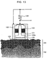
- Fig. 12 shows an arrangement example of a detecting device wherein the electric potential of the skin is detected using electrostatic induction, and the depth at which the dermal tissue is positioned is detected based upon the detected electric potential, whereby the internal pattern beneath the epidermis is obtained.
- the electrostatic capacitance between the detecting electrode and the dermal layer is detected using the fact that the epidermal layer relatively exhibits a nature near being dielectric while the dermal layer exhibits high electric conductivity.
- the detecting device shown in Fig. 12 includes multiple fine electrodes 121 two-dimensionally arrayed with micromachining technology so as to form a detecting electrode plane for being in contact with the surface of the skin.
- electrostatic capacitance is formed between each fine electrode 121 on the detecting electrode plane and the dermal layer.
- the distance distribution regarding the subcutaneous electric-conductive layer underneath each fine electrode 121 is calculated based upon the electrostatic capacitance which is dependent upon the distance between the electrode and the electric-conductive layer, thereby obtaining the subcutaneous tissue structure.
- electrostatic capacitance is formed between: each of the fine electrodes 121 forming the detecting electrode plane positioned parallel to the skin; and the skin, and the terminal voltage of each electric capacitance is measured, whereby the dermal-layer structure is obtained.
- a cylindrical metal casing 22 stores the aforementioned fine electrode 121 held by an insulating support member 123.
- the fine electrode 121 is electrically connected to the casing 22 through a resistor 24 having high electrical resistance.
- the aforementioned fine electrode 121 faces the skin with a predetermined gap therebetween at an opening 122a of the casing 122.
- the present detecting device has a problem of extremely unstable output signals since the surface of the skin having the nature near a dielectric is readily affected by electrostatic induction due to noise or the like from an external AC power supply or a fluorescent lamp, and the surface structure of the skin readily exhibits various conditions due to separation of the horny layer, or the like.
- a method is known for detecting fingerprints or the like, wherein output signals are detected while applying high-frequency electric signals to the human body. Such a method may be applied to detection of the tissue structure wherein the epidermal pattern corresponds to the dermal pattern, such as the fingerprints or the like.
- the aforementioned method cannot be applied to detection of the dermal pattern of other skin tissue wherein the epidermal pattern does not correspond to the dermal pattern.
- the detecting device detects the epidermal pattern.
- the epidermal pattern which does not correspond to the dermal pattern does not exhibit sufficient stability, unlike the fingerprints, and accordingly, the aforementioned method cannot be employed for the biometric authentication using detection of such tissue.
- the detecting device includes a dielectric thin film 125 disposed at the opening of the metal casing 122 as shown in Fig. 13, for example.
- the dielectric thin film 125 is positioned between the metal casing 122 and the skin with which the detecting device is pressed into contact.
- the dielectric thin film 125 is in contact with the metal casing 122 which stores the fine electrode 121 and is connected to the ground, whereby electrostatic capacitance is formed between casing 122 and the skin, as well.
- such a configuration has the advantage of suppressing adverse effects due to unstable conditions of the surface structure of the horny tissue of the skin.
- the detecting device includes an electret film 126 on the surface of each fine electrode 121 forming the detecting electrode plane.
- the electret film 126 is formed of a tetrafluoroethylene film or the like and semi-permanently holds electric charges.
- the electrostatic capacitance is formed between the fine electrode 121 and the dermal tissue (electrically conductive tissue) with a bias voltage due to the permanent polarization of the electret film 126 without externally applying high frequency bias voltage, thereby enabling detection of the distribution of difference in the electrostatic capacitance between the fine electrodes 121, and thereby enabling detection of the deep-layer structure of the skin such as the dermal layer or the like covered with the epidermal tissue of the skin in a noninvasive manner.
- the fine electrode 121 having the electret film 126 is disposed at the opening 122a of the aforementioned casing 122.
- the detecting device is positioned such that the opening 122a faces the tissue, whereby electrostatic capacitance is formed between the fine electrode 121 and the skin through the dielectric thin film 125.
- the casing 122 serves as a counter electrode as to the skin, and is grounded.
- the electrode within the opening 122a serves as a detection electrode. Accordingly, change in the electric potential due to the epidermal tissue is common to both the electrodes, and accordingly, the components thereof exhibit reverse polarity between both the electrodes, leading to canceling out one another.
- change in the electric potential at a deep portion of the skin causes electrostatic capacitance between the dermal layer having electric conductivity and the fine electrode 121 serving as a detection electrode, thereby enabling detection of change in the electric potential at the deep portion of the skin.
- no bias voltage due to an electret film or the like is applied to the capacitance formed by the casing 122, and accordingly, change in the electric potential of the deep layer of the skin is not detected by measuring the capacitance formed by the casing 122 due to charges on the surface of the skin.
- the present arrangement allows the detecting device to precisely detect changes in the electric potential of the deep layer of the skin alone, while canceling out adverse effects due to electrostatic induction of the skin surface, charges thereon, or the like.
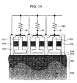
- Fig. 14 shows an arrangement having a configuration wherein the aforementioned detection electrodes (fine electrodes 121) are two-dimensionally arrayed in the form of a matrix, and having a function wherein the conductive-layer structure beneath the epidermis is obtained using the amplitude of the electric potential which is changed synchronously with the entire human body due to walking or the like.
- the first mechanism is essentially the same as with a capacitor microphone.
- the capacitor microphone has a mechanism wherein the gap between a diaphragm and an electret electrode changes due to vibration of the diaphragm, the electrostatic capacitance (C) of the gap changes due to the vibration, and the signals due to change in the electrostatic capacitance are subjected to impedance conversion through the gate of an FET, whereby the vibration of the diaphragm is detected.
- the detecting device has the same configuration as with the capacitance microphone, except for the configuration wherein a dielectric film is included instead of the diaphragm, which is pressed into contact with the tissue of the human body at the time of measurement, whereby charge coupling occurs between the detecting device and the tissue of the human body through the dielectric film.
- capacitance electrostatic capacitance
- the electrostatic capacitance of the human body and the electrostatic capacitance of the gap are combined due to charge coupling.
- the electrostatic capacitance (C) of the human body changes corresponding to the distance between the ground and the position of the foot in the space. That is to say, in a case wherein the foot is in contact with the ground, the capacitance of the human body is great. On the other hand, in a case wherein the foot is positioned away from the ground, the electrostatic capacitance of the human body is extremely small due to an air layer having a low dielectric constant between the sole (of a shoe) and the ground. On the other hand, the greater the contact area between the foot and the ground, the grater the electrostatic capacitance is. Note that the electrostatic capacitance C is represented by the following Expression.
- the second mechanism is that the electrode itself makes an action serving as a charge sensor. That is to say, the electrode stored in the metal casing of the detecting device, which faces the tissue through the dielectric film, detects change in the electric potential induced on the dielectric film due to charge of the human body in the form of a waveform.
- the waveform detected on the human body is formed according to the two mechanisms as described above, i.e., it is assumed that the waveform is essentially formed not due to the electric potential, but due to charge. That is to say, it is assumed that the phenomenon represented by the following Expression occurs. Note that the assumption has been confirmed by reproducing the observed waveform by simulation using the equivalent circuit method.
- the waveform While change in the aforementioned charge exhibits generally the same waveform over the entire human body, the waveform exhibits different amplitude corresponding to the fine structure of the skin tissue, in particular, corresponding to the relation between the epidermis and the dermal layer.
- the waveform due to change in charge changes synchronously over the entire human body. Accordingly, with the present arrangement, comparison is made for the amplitude of the waveform detected by each of the fine detecting electrodes arrayed in the form of a two-dimensional matrix, thereby measuring the distance between the electrode and the dermal layer for each electrode, and thereby obtaining the structure beneath the epidermis.
- each fine electrode 121 without active charge generating means such as an electrode for applying charges or the like, using the fact that charge changes on the human body due to interaction between the foot and the ground by motions wherein the foot is off the ground and touches the ground at the time of walking or the like. Then, the difference in the amplitude between the waveforms occurring due to change in charge synchronously over the entire human body due to motions of the user is converted into the distance between the surface of the skin and the tissue beneath the epidermis, thereby detecting the deep-layer structure beneath the epidermis such as the dermal layer or the like underneath the detecting electrode.
- a method or the like has been proposed, wherein additional transmission means such as an electrode, a transducer, or the like, is provided for being in contact with the human body in addition to the detecting electrodes, a predetermined ultrasonic waves or high-frequency signals are actively applied with the transmission means so as to propagate on the human body, the signals thus propagating on the human body are detected with fine electrodes on the skin, and determination is made whether or not the face of each fine electrode is in contact with the skin, thereby obtaining the fingerprint pattern of the user.
- additional transmission means such as an electrode, a transducer, or the like
- the epidermal pattern is not detected, but the structure of the tissue beneath the epidermis (e.g., the roughness pattern of the dermal layer) is detected by measuring electrostatic capacitance as described above, thereby solving all the aforementioned problems.
- biometric authentication is performed by detecting the structure of the tissue beneath the epidermis, and accordingly, the "biometric authentication” and the "living-tissue discrimination” are integrated. Accordingly, the system can discriminate and reject the tissue cut off from the body of the user by detecting absence of blood flow even if the tissue is alive by soaking in a physiological salt solution. Furthermore, the tissue which is to be authenticated needs to exhibit normal pulmonary circulation, normal heart beat, normal blood flow, and normal hemoglobin ratio in blood. Accordingly, if other persons cut off the arm of the user with a surgical method for "spoofing", there is the need to connect the blood vessels of the arm to a heart-lung machine, and to precisely reproduce the heat-beat wave.
- a wearable information device or a mobile information device includes detecting means for detecting the pattern of tissue, blood vessels, or the like, beneath the epidermis wherein visual observation is difficult under natural light, on the face thereof for being in contact with the skin of the user at the time of the user holding or wearing the information device, the skin-tissue pattern beneath the epidermis on the contact face between the body of the user and the information device is detected at the time of the user holding or wearing the information device, the detected pattern is compared to the patterns which have been registered in the information device or a server computer connected to the information device via network, thereby enabling the system to permit or restrict at least a part of the service provided from the information device or the network system based upon the detection results, i.e., thereby enabling so-called "access control".
- the present invention is applied to a wearable authentication device such as wristwatch-type authentication device, or the like, for example.
- a wearable authentication device such as wristwatch-type authentication device, or the like
- the authentication device needs to be closely fit to the body of the user without looseness so as not to be deviated from the fitting position even if the user moves.
- the system needs to determine the portion of the skin which is to be authenticated.
- an arrangement may be made wherein the interference pattern is registered for a wide skin region including the target region.
- such an arrangement requires pattern matching processing for searching the aforementioned wide region for a matched pattern, leading to a great processing load. Such a great load is undesirable for a mobile authentication device from the perspective of power consumption and so forth.
- the center of a whirl-shaped pattern, a horseshoe-shaped pattern, or the like can be easily detected, and furthermore, the area of the surface of the finger having such a structure is narrow, thereby facilitating search for the position which is to be authenticated.
- other ordinary portions have relatively large area as compared with the fingertip, and have fine skin pattern having no geometric structure which facilitates search for the position which is to be authenticated, unlike the whirl-shaped pattern of the fingerprints, except for limited special portions, leading to extreme difficulty in search for the region which is to be authenticated.
- an arrangement may be made wherein the skin pattern is registered for a wide region beforehand as described above, and the system determines whether or not the pattern detected at the time of authentication is included in the aforementioned registered pattern.
- the skin pattern is preferably registered for the whole body.
- such an arrangement is not undesirable from the practical perspective as described above.
- the authentication device may deviate from the region at the time of authentication due to flexibility of the human body, or difference in the position to which the authentication device is fit for each authentication.
- the skin containing a fork structure of the subcutaneous blood vessel is preferably used as the skin which is to be authenticated.
- the direction of the aforementioned principal axis can be easily obtained using the fork structure.
- an arrangement may be made wherein the positional relation regarding the fork structure is determined and stored beforehand at the time of user registration, thereby enabling adjustment of the portion of the skin which is to be authenticated at the time of user authentication based upon the position of the blood-vessel fork structure in a simple manner.
- the skin structure comprises the epidermal tissue which has no blood vessels and is passive to the body temperature, and the dermal tissue which has blood vessels and actively affects the temperature through blood flow. This causes a relatively high temperature in the dermal tissue as compared with the epidermal tissue, except for special situations wherein heat is externally applied, such as exposure of direct sunlight to the body surface.
- a detecting device detects the structure of tissue beneath the epidermis using the aforementioned mechanism.
- the detecting device has a configuration wherein fine devices for detecting temperature such as thermistor bolometers, thermopiles, or the like, are two-dimensionally arrayed instead of the fine electrodes described above, and temperature is measured at each point. In this case, difference in temperature is detected between the fine devices corresponding to the thickness of the epidermal layer or the like underneath each fine device.
- the detecting device detects the roughness structure of the dermal layer beneath the epidermis using the aforementioned mechanism.
- thermopiles having a sensitive range corresponding to infrared light emitted from the human body are preferably employed as the fine devices for detecting temperature, thereby enabling detection while preventing adverse effects due to an external heat source such as sunlight or the like.
- infrared-light detecting means which is a temperature detecting means
- the detecting face thus formed is positioned close to the surface of the skin, thereby detecting the dermal layer pattern beneath the epidermal tissue, using the fact that the living tissue emits infrared light with a unique wavelength (e.g., wavelength of around 10 ⁇ m) due to the body temperature.
- difference in the infrared magnitude is detected between the infrared detecting sensor units forming the matrix-shaped infrared detecting means, corresponding the thickness of the epidermis or the distance between the sensor unit and the dermis serving as an infrared source.
- the detecting device detects the structure of the subcutaneous tissue, e.g., the roughness pattern of the dermal layer, based upon the infrared magnitude distribution.
- an arrangement may be made wherein the positions of the blood vessels are detected using the fact that a portion containing the subcutaneous blood vessels exhibits a relatively high temperature as compared with the other portions, thereby enabling biometric authentication. Furthermore, an arrangement may be made wherein the position or the direction of the portion which is to be authenticated is determined based upon a detected image of blood capillaries. Furthermore, living-tissue discrimination may be performed based upon a detected image of blood capillaries, as well.
- the present invention enables ubiquitous biometric authentication using not only a special portion such as the fingertip or the like, but also any desired portion of the skin of the user. Furthermore, such a portion which is to be authenticated cannot be observed from the outside, unlike the fingerprints, and accordingly, it is difficult for other persons to identify the portion of the user body which is used for authentication.
- the present invention has the advantage of high security of privacy, as well as the advantage of high security against forgery.
- the present invention provides an authentication method using the portion having active blood flow or active circulation of body fluid, such as the dermal tissue.
- the properties of such a portion exhibits high sensitivity to change in the blood flow or circulation of body fluid, thereby providing essential and complete integration of biometric authentication means and living-tissue discrimination.
- the present invention provides biometric authentication while suppressing the risk of surgical hazard, i.e., improving safety of the user.
- the present invention may be applied to a wearable detecting device and a wearable authentication device having a detecting portion for being in contact with the skin of the human body, thereby enabling biometric authentication using daily actions of the user without any special user operations. Furthermore, even in the event that detection error or authentication error occurs, retry processing is performed without any particular user operations, and is not troublesome.
Landscapes
- Engineering & Computer Science (AREA)
- Physics & Mathematics (AREA)
- General Physics & Mathematics (AREA)
- Theoretical Computer Science (AREA)
- Human Computer Interaction (AREA)
- Multimedia (AREA)
- Health & Medical Sciences (AREA)
- General Health & Medical Sciences (AREA)
- Computer Vision & Pattern Recognition (AREA)
- Life Sciences & Earth Sciences (AREA)
- Medical Informatics (AREA)
- Pathology (AREA)
- Nuclear Medicine, Radiotherapy & Molecular Imaging (AREA)
- Radiology & Medical Imaging (AREA)
- Quality & Reliability (AREA)
- Probability & Statistics with Applications (AREA)
- Vascular Medicine (AREA)
- Analytical Chemistry (AREA)
- Immunology (AREA)
- Biochemistry (AREA)
- Chemical & Material Sciences (AREA)
- Surgery (AREA)
- Heart & Thoracic Surgery (AREA)
- Molecular Biology (AREA)
- Biomedical Technology (AREA)
- Animal Behavior & Ethology (AREA)
- Public Health (AREA)
- Veterinary Medicine (AREA)
- Biophysics (AREA)
- Measurement Of The Respiration, Hearing Ability, Form, And Blood Characteristics Of Living Organisms (AREA)
- Collating Specific Patterns (AREA)
- Investigating Or Analysing Materials By Optical Means (AREA)
Abstract
Description


Claims (58)
- A living-tissue pattern detecting method wherein the roughness distribution pattern of deep-layer tissue of skin covered with epidermal tissue is detected for extracting a unique pattern of living tissue.
- A living-tissue pattern detecting method according to Claim 1, wherein said deep-layer tissue of the skin is dermal tissue.
- A living-tissue pattern detecting method according to Claim 1, wherein said roughness distribution pattern is optically detected using difference in optical properties between said epidermal tissue and said deep-layer tissue of the skin.
- A living-tissue pattern detecting method according to Claim 3, wherein polarized light is cast on said tissue; and reflected light is detected through a polarizing filter with a polarizing plane orthogonal to that of said polarizing light, for detecting said roughness distribution pattern.
- A living-tissue pattern detecting method according to Claim 4, wherein long-wavelength light is used as said polarizing light.
- A living-tissue pattern detecting method according to Claim 5, wherein near-infrared light is used as said long-wavelength light.
- A living-tissue pattern detecting method according to Claim 4, wherein wavelength components changed due to reflection are selected by means which allow light with a predetermined frequency to pass through, or means which reflect light with a predetermined frequency.
- A living-tissue pattern detecting method according to Claim 4, wherein incident angle of said polarized light is controlled so as to adjust the depth for detecting the object which is to be detected.
- A living-tissue pattern detecting method according to Claim 3, wherein illumination light is cast onto said tissue so as to cause interference between a part of said illumination light and reflected light for detecting change in wavelength components of the reflected light in the form of an interference pattern, thereby extracting a unique pattern of living tissue.
- A living-tissue pattern detecting method according to Claim 1, wherein said roughness distribution pattern is electrically detected using difference in electric properties between epidermal tissue and deep-layer tissue of the skin.
- A living-tissue pattern detecting method according to Claim 10, wherein the electric potential of the skin is measured using electrostatic induction so as to detect the depth at which dermal tissue beneath epidermis is positioned, thereby detecting the tissue structure beneath epidermis.
- A living-tissue pattern detecting method according to Claim 11, wherein a plurality of fine electrodes are arrayed in parallel at a predetermined pitch for being fit to the skin which is to be detected.
- A living-tissue pattern detecting method according to Claim 12, wherein capacitance coupling is formed between each fine electrode and dermal tissue, and distance distribution regarding the conductive layer beneath epidermis is calculated based upon electrostatic capacitance thus formed underneath each fine electrode, thereby detecting said tissue structure beneath the epidermis.
- A living-tissue pattern detecting method according to Claim 13, wherein said fine electrodes each of which are stored in a metal casing through an insulating member are disposed at a predetermined pitch, and said metal casing includes a dielectric thin film for being fit to the skin so as to be introduced between said metal casing and the skin.
- A living-tissue pattern detecting method according to Claim 13, wherein an electret film is provided on the surface of said fine electrode, and electrostatic capacitance is formed between said fine electrode and dermal tissue with a bias voltage due to permanent polarization of said electret film.
- A living-tissue pattern detecting method according to Claim 12, wherein change in charge on living tissue due to motions is detected with said fine electrode, and difference in the amplitude of waveforms due to change in charge between said fine electrodes is converted into distance between the surface of the skin and tissue beneath epidermis.
- A living-tissue pattern detecting device including means for detecting the roughness distribution pattern of deep-layer tissue of skin covered with epidermal tissue.
- A living-tissue pattern detecting device according to Claim 17, wherein said means for detecting said roughness distribution pattern have a function for optically detecting said roughness distribution pattern.
- A living-tissue pattern detecting device according to Claim 18, comprising: an illumination optical system including a light source for casting light onto a portion which is to be detected, and a polarizing filter for aligning the polarizing plane of illumination light; and an imaging optical system including a light-receiving unit for receiving reflected light from said portion which is to be detected, and a polarizing filter with a polarizing plane orthogonal to that of said polarizing filter.
- A living-tissue pattern detecting device according to Claim 19, wherein said light source comprises a near-infrared light source.
- A living-tissue pattern detecting device according to Claim 19, further comprising means for selecting wavelength components of said reflected light, changed due to reflection.
- A living-tissue pattern detecting device according to Claim 19, further comprising a moving reflecting mirror for controlling the incident angle of light cast from said light source.
- A living-tissue pattern detecting device according to Claim 18, comprising: an illumination optical system including a light source for casting light onto a portion which is to be detected; a reference optical system for causing an interference pattern for detecting change in wavelength components of the reflected light; and an imaging optical system for detecting said interference pattern.
- A living-tissue pattern detecting device according to Claim 23, wherein said light source comprises a white light source.
- A living-tissue pattern detecting device according to Claim 23, wherein a plurality of detecting units each of which includes said illumination optical system, said reference optical system, and said imaging optical system, are arrayed.
- A living-tissue pattern detecting device according to Claim 23, further comprising a moving mirror for controlling the incident position at which light is cast from said light source.
- A living-tissue pattern detecting device according to Claim 17, wherein said means for detecting the roughness distribution pattern have a function for electrically detecting the roughness distribution pattern.
- A living-tissue pattern detecting device according to Claim 27, wherein the electric potential of the skin is measured using electrostatic induction for detecting the depth at which dermal tissue beneath epidermis is positioned, thereby detecting tissue structure beneath epidermis.
- A living-tissue pattern detecting device according to Claim 28, further comprising a plurality of fine electrodes arrayed in parallel at a predetermined pitch upon the skin which is to be detected, wherein the distance distribution regarding a conductive layer beneath epidermis is calculated based upon electrostatic capacitance underneath each fine electrode, thereby detecting the tissue structure beneath epidermis.
- A living-tissue pattern detecting device according to Claim 29, wherein said fine electrodes each of which are stored in a metal casing through an insulating member are arrayed at a predetermined pitch, and wherein said metal casing includes a dielectric thin film to be introduced between said metal casing and the skin.
- A living-tissue pattern detecting device according to Claim 29, wherein each fine electrode includes an electret film on the surface thereof.
- A biometric authentication method wherein the roughness distribution pattern of deep-layer tissue of the skin covered with epidermal tissue is detected, and said roughness distribution pattern thus detected is compared to a pattern which has been registered beforehand, whereby biometric authentication is performed.
- A biometric authentication method according to Claim 32, wherein said deep-layer tissue of the skin is dermal tissue.
- A biometric authentication method according to Claim 32, wherein said roughness distribution pattern is optically detected using difference in optical properties between said epidermal tissue and said deep-layer structure of the tissue.
- A biometric authentication method according to Claim 34, wherein polarized light is cast on said tissue, and reflected light is detected through a polarizing filter with a polarizing plane orthogonal to that of said polarizing light, for detecting said roughness distribution pattern.
- A biometric authentication method according to Claim 34, wherein illumination light is cast onto said tissue so as to cause interference between a part of said illumination light and reflected light for detecting change in wavelength components of the reflected light in the form of an interference pattern, thereby extracting a unique pattern of living tissue.
- A biometric authentication method according to Claim 32, wherein a fork structure of a subcutaneous blood vessel is used as the portion which is to be detected, and wherein said portion which is to be detected and the direction of the principal axis are determined at the time of authentication, based upon said fork structure using the relation between said principal axis and said fork structure registered beforehand.
- A biometric authentication method according to Claim 37, wherein living-tissue discrimination is made using said subcutaneous blood vessel.
- A biometric authentication method according to Claim 38, wherein living-tissue discrimination is made using change in absorbance due to change in blood flow in said subcutaneous blood vessel.
- A biometric authentication method according to Claim 32, wherein said roughness distribution pattern is electrically detected using difference in electric properties between epidermal tissue and deep-layer tissue of the skin.
- A biometric authentication method according to Claim 40, wherein the electric potential of the skin is measured using electrostatic induction so as to detect the depth at which dermal tissue beneath epidermis is positioned, thereby detecting the tissue structure beneath epidermis.
- A biometric authentication method according to Claim 32, wherein the tissue structure beneath epidermis covered with epidermal tissue is detected using difference in temperature between epidermal tissue and deep-layer tissue of the skin.
- A biometric authentication method according to Claim 42, wherein fine temperature detecting devices are arrayed,
and wherein said tissue structure beneath epidermis is detected based upon difference in temperature between said temperature detecting devices. - A biometric authentication method according to Claim 43, wherein said difference in temperature is detected in the form of difference in magnitude of infrared light.
- A biometric authentication device including means for detecting the roughness distribution pattern of deep-layer tissue of the skin covered with epidermal tissue, wherein said roughness distribution pattern thus detected is compared to a pattern which has been registered beforehand, whereby biometric authentication is performed.
- A biometric authentication device according to Claim 45, wherein said means for detecting the roughness distribution pattern has a function for optically detecting said roughness distribution pattern.
- A biometric authentication device according to Claim 46, comprising: an illumination optical system including a light source for casting light onto a portion which is to be detected, and a polarizing filter for aligning the polarizing plane of illumination light cast from said light source; and an imaging optical system including a light-receiving unit for receiving reflected light from said portion which is to be detected, and a polarizing filter with a polarizing plane orthogonal to that of said polarizing filter.
- A biometric authentication device according to Claim 46, comprising: an illumination optical system including a light source for casting light onto a portion which is to be detected; a reference optical system for causing an interference pattern for detecting change in wavelength components of the reflected light; and an imaging optical system for detecting said interference pattern.
- A biometric authentication device according to Claim 45, including means for determining the position which is to be detected and the direction of the principal axis based upon the structure of a subcutaneous blood vessel.
- A biometric authentication device according to Claim 49, comprising:an interference-light detecting unit for detecting the roughness distribution pattern of deep-layer tissue of the skin covered with epidermal tissue;a moving mirror for controlling the incident angle of illumination light cast from said interference-light detecting unit;a blood-vessel position detecting unit for detecting the positions of subcutaneous blood vessels based upon information from said interference-light detecting unit;a blood-vessel data storage unit for storing an images of subcutaneous blood vessels;a blood-vessel position comparison unit for comparing the positions of the detected blood vessels to blood-vessel data stored beforehand;a mirror control unit for controlling the angle of said moving mirror based upon control information from said blood-vessel position detecting unit and said blood-vessel position comparison unit;an interference-pattern storage unit for storing the interference pattern due to deep-layer tissue of the skin;a matching unit for performing matching of the positions of blood vessels and said interference pattern; andan interference-pattern comparison unit for comparing interference-pattern information received from said interference-light detecting unit to the interference pattern stored in said interference-pattern storage unit.
- A biometric authentication device according to Claim 45, wherein said means for detecting the roughness distribution pattern have a function for electrically detecting the roughness distribution pattern.
- A biometric authentication device according to Claim 51, wherein the electric potential of the skin is measured using electrostatic induction for detecting the depth at which dermal tissue beneath epidermis is positioned, thereby detecting tissue structure beneath epidermis.
- A biometric authentication device according to Claim 52, wherein further comprising a plurality of fine electrodes arrayed in parallel at a predetermined pitch upon the skin which is to be detected, wherein the distance distribution regarding a conductive layer beneath epidermis is calculated based upon electrostatic capacitance underneath each fine electrode, thereby detecting the tissue structure beneath epidermis.
- A biometric authentication device according to Claim 45, wherein said means for detecting the roughness distribution pattern have a function for detecting tissue structure beneath epidermis covered with epidermal tissue using difference in temperature between said epidermal tissue and said deep-layer tissue of the skin.
- A biometric authentication device according to Claim 54, including a plurality of temperature detecting devices arrayed upon the skin which is to be detected, wherein the roughness distribution regarding the tissue beneath epidermis is detected based upon difference in temperature between said temperature detecting devices, whereby the tissue structure beneath epidermis is detected.
- A biometric authentication device according to Claim 54, including a plurality of infrared detecting devices arrayed upon the skin which is to be detected, wherein the roughness distribution regarding the tissue beneath epidermis is detected based upon difference in the magnitude of infrared light between said infrared detecting devices, whereby the tissue structure beneath epidermis is detected.
- A biometric authentication method wherein near-infrared light is cast onto the tissue through a polarizing filter, as well as detecting reflected light through a polarizing filter with a polarizing plane orthogonal to that of said polarizing filter, so as to detect an image of blood capillaries beneath epidermis or the three-dimensional distribution pattern thereof, and wherein comparison is made between: said image of blood capillaries beneath epidermis or said three-dimensional distribution pattern thereof thus detected; and a pattern registered beforehand, whereby biometric authentication is performed.
- A biometric authentication device comprising: an illumination optical system including a light source for casting near-infrared light onto a portion which is to be detected, and a polarizing filter for aligning the polarizing plane of illumination light cast from said light source; and an imaging optical system including an imaging unit for taking an image of reflected light from said portion which is to be detected, and a polarizing filter with the polarizing plane orthogonal to that of said polarizing filter; wherein comparison is made between: an acquired image of blood capillaries beneath epidermis or the three-dimensional distribution pattern thereof; and a pattern registered beforehand, whereby biometric authentication is performed.
Priority Applications (2)
| Application Number | Priority Date | Filing Date | Title |
|---|---|---|---|
| EP09163990A EP2098977B1 (en) | 2002-05-09 | 2003-05-07 | Method of detecting biological pattern, biological pattern detector, method of biological certificate and biological certificate apparatus |
| EP10176610.3A EP2328111B1 (en) | 2002-05-09 | 2003-05-07 | Blood vessel authentication |
Applications Claiming Priority (5)
| Application Number | Priority Date | Filing Date | Title |
|---|---|---|---|
| JP2002134534 | 2002-05-09 | ||
| JP2002134534A JP4499341B2 (en) | 2002-05-09 | 2002-05-09 | Biometric authentication device and biometric authentication method |
| JP2002134569A JP4247656B2 (en) | 2002-05-09 | 2002-05-09 | Biological pattern detection method and biological pattern detection device |
| JP2002134569 | 2002-05-09 | ||
| PCT/JP2003/005696 WO2003096272A1 (en) | 2002-05-09 | 2003-05-07 | Method of detecting biological pattern, biological pattern detector, method of biological certificate and biological certificate apparatus |
Related Child Applications (3)
| Application Number | Title | Priority Date | Filing Date |
|---|---|---|---|
| EP10176610.3A Division EP2328111B1 (en) | 2002-05-09 | 2003-05-07 | Blood vessel authentication |
| EP09163990A Division EP2098977B1 (en) | 2002-05-09 | 2003-05-07 | Method of detecting biological pattern, biological pattern detector, method of biological certificate and biological certificate apparatus |
| EP09163990.6 Division-Into | 2009-06-29 |
Publications (3)
| Publication Number | Publication Date |
|---|---|
| EP1503330A1 true EP1503330A1 (en) | 2005-02-02 |
| EP1503330A4 EP1503330A4 (en) | 2008-06-11 |
| EP1503330B1 EP1503330B1 (en) | 2010-06-02 |
Family
ID=29422383
Family Applications (3)
| Application Number | Title | Priority Date | Filing Date |
|---|---|---|---|
| EP09163990A Expired - Lifetime EP2098977B1 (en) | 2002-05-09 | 2003-05-07 | Method of detecting biological pattern, biological pattern detector, method of biological certificate and biological certificate apparatus |
| EP03721050A Expired - Lifetime EP1503330B1 (en) | 2002-05-09 | 2003-05-07 | Method of detecting biological pattern, biological pattern detector, method of biological certificate and biological certificate apparatus |
| EP10176610.3A Expired - Lifetime EP2328111B1 (en) | 2002-05-09 | 2003-05-07 | Blood vessel authentication |
Family Applications Before (1)
| Application Number | Title | Priority Date | Filing Date |
|---|---|---|---|
| EP09163990A Expired - Lifetime EP2098977B1 (en) | 2002-05-09 | 2003-05-07 | Method of detecting biological pattern, biological pattern detector, method of biological certificate and biological certificate apparatus |
Family Applications After (1)
| Application Number | Title | Priority Date | Filing Date |
|---|---|---|---|
| EP10176610.3A Expired - Lifetime EP2328111B1 (en) | 2002-05-09 | 2003-05-07 | Blood vessel authentication |
Country Status (6)
| Country | Link |
|---|---|
| US (7) | US20050180620A1 (en) |
| EP (3) | EP2098977B1 (en) |
| KR (2) | KR101035667B1 (en) |
| CN (1) | CN1662931A (en) |
| DE (1) | DE60332829D1 (en) |
| WO (1) | WO2003096272A1 (en) |
Cited By (7)
| Publication number | Priority date | Publication date | Assignee | Title |
|---|---|---|---|---|
| WO2009077713A1 (en) * | 2007-12-14 | 2009-06-25 | Rolls-Royce Plc | A sensor arrangement |
| EP1832231A4 (en) * | 2004-12-28 | 2009-11-11 | Sony Corp | Bioimaging device |
| GB2443366B (en) * | 2005-08-17 | 2010-11-10 | Ultra Scan Corp | Use of papilla mapping to determine a friction-ridge surface |
| EP2413263A1 (en) * | 2009-03-24 | 2012-02-01 | Hanscan IP B.V. | 3d biometric scanner |
| US8244006B2 (en) | 2007-10-03 | 2012-08-14 | Hitachi Media Electronics Co., Ltd. | Finger vein image inputting device and apparatus using the same |
| US8400313B2 (en) | 2007-01-19 | 2013-03-19 | Asahi Kasei Kabushiki Kaisha | Vehicle driver sleep state classification generating device based on Hidden Markov Model, sleep state classification device and warning device |
| CN106971136A (en) * | 2016-01-14 | 2017-07-21 | 深圳市汇顶科技股份有限公司 | Biological monitor and its processing method |
Families Citing this family (111)
| Publication number | Priority date | Publication date | Assignee | Title |
|---|---|---|---|---|
| GB2352512B (en) * | 1999-07-23 | 2002-03-13 | Toshiba Res Europ Ltd | A radiation probe and detecting tooth decay |
| KR101035667B1 (en) | 2002-05-09 | 2011-05-19 | 소니 주식회사 | Biometric pattern detecting device, a personal authentication device and method |
| KR20060002923A (en) | 2003-04-04 | 2006-01-09 | 루미다임 인크. | Multispectral biometric sensor |
| US7460696B2 (en) | 2004-06-01 | 2008-12-02 | Lumidigm, Inc. | Multispectral imaging biometrics |
| US7668350B2 (en) | 2003-04-04 | 2010-02-23 | Lumidigm, Inc. | Comparative texture analysis of tissue for biometric spoof detection |
| US7539330B2 (en) * | 2004-06-01 | 2009-05-26 | Lumidigm, Inc. | Multispectral liveness determination |
| US7751594B2 (en) | 2003-04-04 | 2010-07-06 | Lumidigm, Inc. | White-light spectral biometric sensors |
| US7627151B2 (en) * | 2003-04-04 | 2009-12-01 | Lumidigm, Inc. | Systems and methods for improved biometric feature definition |
| US7394919B2 (en) * | 2004-06-01 | 2008-07-01 | Lumidigm, Inc. | Multispectral biometric imaging |
| US7263213B2 (en) * | 2003-12-11 | 2007-08-28 | Lumidigm, Inc. | Methods and systems for estimation of personal characteristics from biometric measurements |
| JP4217646B2 (en) * | 2004-03-26 | 2009-02-04 | キヤノン株式会社 | Authentication method and authentication apparatus |
| US8229185B2 (en) | 2004-06-01 | 2012-07-24 | Lumidigm, Inc. | Hygienic biometric sensors |
| US8787630B2 (en) | 2004-08-11 | 2014-07-22 | Lumidigm, Inc. | Multispectral barcode imaging |
| US20060165261A1 (en) * | 2005-01-24 | 2006-07-27 | Pira Robert K | Structure for supporting a human hand in an operating environment |
| US7801338B2 (en) | 2005-04-27 | 2010-09-21 | Lumidigm, Inc. | Multispectral biometric sensors |
| WO2007033380A2 (en) * | 2005-09-16 | 2007-03-22 | Pira Robert K | Biometric sensing device and method |
| US20080226146A1 (en) * | 2005-09-16 | 2008-09-18 | Farimex S.A. | Biometric Detector and Identity Control Device |
| FR2899357B1 (en) * | 2006-03-29 | 2008-06-20 | Sagem Defense Securite | PROCESSING BIOMETRIC DATA IN A MULTI DIMENSIONAL REFERENTIAL. |
| US7995808B2 (en) | 2006-07-19 | 2011-08-09 | Lumidigm, Inc. | Contactless multispectral biometric capture |
| US8175346B2 (en) | 2006-07-19 | 2012-05-08 | Lumidigm, Inc. | Whole-hand multispectral biometric imaging |
| CN101506826A (en) | 2006-07-19 | 2009-08-12 | 光谱辨识公司 | Multibiometric multispectral imager |
| US8355545B2 (en) | 2007-04-10 | 2013-01-15 | Lumidigm, Inc. | Biometric detection using spatial, temporal, and/or spectral techniques |
| US7804984B2 (en) | 2006-07-31 | 2010-09-28 | Lumidigm, Inc. | Spatial-spectral fingerprint spoof detection |
| US7801339B2 (en) | 2006-07-31 | 2010-09-21 | Lumidigm, Inc. | Biometrics with spatiospectral spoof detection |
| CN100453040C (en) * | 2007-01-23 | 2009-01-21 | 天津理工大学 | Identity recognition instrument based on characteristics of subcutaneous vein of dorsum of hand and recognition method |
| EP2143045A1 (en) * | 2007-03-14 | 2010-01-13 | Spectros Corporation | Metabolism-or biochemical-based anti-spoofing biometrics devices, systems, and methods |
| US8285010B2 (en) | 2007-03-21 | 2012-10-09 | Lumidigm, Inc. | Biometrics based on locally consistent features |
| WO2008131201A1 (en) * | 2007-04-19 | 2008-10-30 | Global Rainmakers, Inc. | Method and system for biometric recognition |
| CN101295350A (en) * | 2007-04-25 | 2008-10-29 | 鸿富锦精密工业(深圳)有限公司 | Fingerprint identification device and portable electronic device |
| KR20100033371A (en) * | 2007-05-07 | 2010-03-29 | 주식회사 이노제스트 | Apparatus and method for recognizing subcutaneous vein pattern |
| JP2008287436A (en) * | 2007-05-16 | 2008-11-27 | Sony Corp | Vein pattern management system, vein pattern registering device, vein pattern authentication device, vein pattern registering method, vein pattern authentication method, program, and vein data structure |
| JP2008287433A (en) * | 2007-05-16 | 2008-11-27 | Sony Corp | Vein pattern management system, vein pattern registering device, vein pattern authentication device, vein pattern registering method, vein pattern authentication method, program, and vein data structure |
| JP4910923B2 (en) | 2007-07-20 | 2012-04-04 | ソニー株式会社 | Imaging apparatus, imaging method, and imaging program |
| ES2329328B1 (en) | 2008-05-23 | 2010-08-30 | Hanscan Ip B.V. | BIOMETRIC PROCEDURE AND SCANNER TO IDENTIFY A PERSON. |
| EP2329767B1 (en) * | 2008-09-02 | 2013-10-23 | QFactor Inc. | Detector, detection method, vein sensor, scanned probe microscope, strain detector, and metal detector |
| US10062356B1 (en) | 2008-09-30 | 2018-08-28 | The United States of America as Represented by the Admin of National Aeronautics and Space Administration | Two and three dimensional near infrared subcutaneous structure imager using real time nonlinear video processing |
| KR101008270B1 (en) * | 2008-11-11 | 2011-01-13 | 전자부품연구원 | A device for measuring thickness of subcutaneous fat capable of compensation with thickness of dermal depth |
| ES2629335T3 (en) * | 2008-12-17 | 2017-08-08 | Fujitsu Limited | Biometric authentication device and biometric authentication method |
| US9138176B2 (en) * | 2009-01-07 | 2015-09-22 | Panasonic Intellectual Property Management Co., Ltd. | Biological information measuring device and control method thereof |
| JP5326792B2 (en) * | 2009-05-14 | 2013-10-30 | ソニー株式会社 | Vein imaging device, positional deviation interpolation method and program |
| JP4548542B1 (en) * | 2009-06-30 | 2010-09-22 | ソニー株式会社 | Information processing apparatus, information processing method, and program |
| US8872908B2 (en) | 2009-08-26 | 2014-10-28 | Lumidigm, Inc | Dual-imager biometric sensor |
| US8451450B2 (en) * | 2009-09-14 | 2013-05-28 | Bio-Rad Laboratories, Inc. | Near real time optical phase conjugation |
| FR2950455B1 (en) | 2009-09-22 | 2013-10-25 | Thales Sa | METHOD FOR DETECTING FALSE FINGER FOR FINGERPRINT ACQUISITION SOFTWARE |
| US8570149B2 (en) | 2010-03-16 | 2013-10-29 | Lumidigm, Inc. | Biometric imaging using an optical adaptive interface |
| US8977013B2 (en) | 2010-07-12 | 2015-03-10 | The Institute For Diagnostic Imaging Research, University Of Windsor | Biometric sensor and method for generating a three-dimensional representation of a portion of a finger |
| JP2012068762A (en) * | 2010-09-21 | 2012-04-05 | Sony Corp | Detection device, detection method, program, and electronic apparatus |
| JP5780053B2 (en) | 2011-08-22 | 2015-09-16 | 富士通株式会社 | Biometric authentication device, biometric authentication method, and program |
| JP5787276B2 (en) | 2011-09-07 | 2015-09-30 | 株式会社リコー | Moisture sensor, moisture detector, and image forming apparatus |
| US8896678B2 (en) | 2011-09-16 | 2014-11-25 | The Invention Science Fund I, Llc | Coregistering images of a region of interest during several conditions using a landmark subsurface feature |
| US8380995B1 (en) * | 2011-11-29 | 2013-02-19 | Google Inc. | Process for login of a computing device with a touchscreen |
| US11399898B2 (en) | 2012-03-06 | 2022-08-02 | Briteseed, Llc | User interface for a system used to determine tissue or artifact characteristics |
| JP5509459B2 (en) * | 2012-03-16 | 2014-06-04 | ユニバーサルロボット株式会社 | Personal authentication method and personal authentication device |
| US9582035B2 (en) | 2014-02-25 | 2017-02-28 | Medibotics Llc | Wearable computing devices and methods for the wrist and/or forearm |
| US9251396B2 (en) * | 2013-01-29 | 2016-02-02 | Diamond Fortress Technologies, Inc. | Touchless fingerprinting acquisition and processing application for mobile devices |
| CN103445764B (en) * | 2013-09-04 | 2014-11-19 | 广州医软智能科技有限公司 | Device and method for monitoring microcirculation imaging |
| WO2015056257A1 (en) * | 2013-10-14 | 2015-04-23 | Avraham Aharoni | Device and system for imaging veins |
| US9582034B2 (en) * | 2013-11-29 | 2017-02-28 | Motiv, Inc. | Wearable computing device |
| US10281953B2 (en) | 2013-11-29 | 2019-05-07 | Motiv Inc. | Wearable device and data transmission method |
| KR102253091B1 (en) * | 2014-01-07 | 2021-05-17 | 삼성전자주식회사 | Method for controlling function and electronic device thereof |
| JP6134662B2 (en) * | 2014-01-31 | 2017-05-24 | 株式会社 日立産業制御ソリューションズ | Biometric authentication device and biometric authentication method |
| KR20150106229A (en) * | 2014-03-11 | 2015-09-21 | 삼성전자주식회사 | Apparatus and method for authenticating a user |
| US10251600B2 (en) | 2014-03-25 | 2019-04-09 | Briteseed, Llc | Vessel detector and method of detection |
| CN103971446A (en) * | 2014-05-13 | 2014-08-06 | 威海华菱光电股份有限公司 | Paper money thickness detecting tool |
| FR3021783B1 (en) | 2014-06-02 | 2016-05-13 | Morpho | METHOD FOR VALIDATING THE AUTHENTICITY OF A HUMAN BODY ELEMENT |
| US9400880B2 (en) | 2014-06-17 | 2016-07-26 | Qualcomm Incorporated | Method and apparatus for biometric-based security using capacitive profiles |
| US10478127B2 (en) | 2014-06-23 | 2019-11-19 | Sherlock Solutions, LLC | Apparatuses, methods, processes, and systems related to significant detrimental changes in health parameters and activating lifesaving measures |
| US9633269B2 (en) * | 2014-09-05 | 2017-04-25 | Qualcomm Incorporated | Image-based liveness detection for ultrasonic fingerprints |
| KR102302844B1 (en) | 2014-10-23 | 2021-09-16 | 삼성전자주식회사 | Method and apparatus certifying user using vein pattern |
| KR101667138B1 (en) * | 2015-02-05 | 2016-10-17 | 고려대학교 산학협력단 | Optical system for detecting biological tissue using polarization property |
| EP4000509B1 (en) | 2015-02-19 | 2023-08-30 | Briteseed, LLC | Surgical system for determining vessel size |
| WO2016134327A1 (en) | 2015-02-19 | 2016-08-25 | Briteseed Llc | System for determining vessel size using light absorption |
| EP3066977A1 (en) | 2015-03-13 | 2016-09-14 | Biowatch SA | A biometric sensor in a wristwatch or wristband for detection of wrist blood vessels |
| US20160270715A1 (en) * | 2015-03-18 | 2016-09-22 | Elc Management Llc | Methods of Treating Wrinkles, Developing Wrinkle Treatments And Evaluating Treatment Efficacy, Based On Newly Discovered Similarities Between Wrinkles And Skin Wounds |
| EP3073414B1 (en) | 2015-03-27 | 2019-07-24 | Biowatch SA | A biometric sensor for detection of wrist blood vessels in a wrist strap |
| US20170091392A1 (en) * | 2015-05-01 | 2017-03-30 | Steven C. White | Biometric identification telemedicine software |
| EP3118762B1 (en) | 2015-07-15 | 2020-03-11 | Biowatch SA | Method, device and computer program for authenticating a user |
| US9722793B2 (en) | 2015-09-09 | 2017-08-01 | Microsoft Technology Licensing, Llc | Personal identification via acoustically stimulated biospeckles |
| US10140534B2 (en) | 2015-09-26 | 2018-11-27 | Qualcomm Incorporated | Ultrasonic imaging devices and methods |
| EP3359021B1 (en) | 2015-10-08 | 2019-07-31 | Briteseed, LLC | System for determining vessel size |
| KR102396249B1 (en) * | 2015-10-14 | 2022-05-09 | 삼성전자주식회사 | Method and apparatus for user authentication using Raman spectrum |
| KR102444674B1 (en) * | 2015-11-20 | 2022-09-16 | 삼성전자주식회사 | Optical measuring apparatus and electronic device including the same |
| US9946943B2 (en) * | 2015-12-07 | 2018-04-17 | Delta Id, Inc. | Methods and apparatuses for birefringence based biometric authentication |
| WO2017100295A1 (en) * | 2015-12-07 | 2017-06-15 | Delta Id, Inc. | Methods and apparatuses for birefringence based biometric authentication |
| JP6660720B2 (en) * | 2015-12-08 | 2020-03-11 | 株式会社日立製作所 | Finger vein authentication device |
| IL243259A0 (en) * | 2015-12-21 | 2016-02-29 | Oren Aharon | Imaging skin cancer detection device |
| US10127661B2 (en) | 2016-01-05 | 2018-11-13 | Industrial Technology Research Institute | Method for evaluating skin tissue and system using the same |
| KR102468133B1 (en) * | 2016-02-29 | 2022-11-18 | 엘지전자 주식회사 | Foot vein authentication device |
| CN106021178B (en) * | 2016-03-28 | 2018-11-06 | 陈威 | A method of calculating related 3 parameters of application on human skin collagen using mathematical model |
| US9554738B1 (en) * | 2016-03-30 | 2017-01-31 | Zyomed Corp. | Spectroscopic tomography systems and methods for noninvasive detection and measurement of analytes using collision computing |
| KR102480294B1 (en) * | 2016-05-04 | 2022-12-23 | 엘지전자 주식회사 | Wearable device and method for controlling wearable device |
| US10235551B2 (en) | 2016-05-06 | 2019-03-19 | Qualcomm Incorporated | Biometric system with photoacoustic imaging |
| US10366269B2 (en) * | 2016-05-06 | 2019-07-30 | Qualcomm Incorporated | Biometric system with photoacoustic imaging |
| US11064893B2 (en) * | 2016-07-20 | 2021-07-20 | Samsung Electronics Co., Ltd. | Real time authentication based on blood flow parameters |
| EP4026489A1 (en) | 2016-08-30 | 2022-07-13 | Briteseed, LLC | System and method for determining vessel size with angular distortion compensation |
| US10515281B1 (en) * | 2016-12-29 | 2019-12-24 | Wells Fargo Bank, N.A. | Blood vessel image authentication |
| US10515255B2 (en) * | 2017-03-24 | 2019-12-24 | Qualcomm Incorporated | Fingerprint sensor with bioimpedance indicator |
| US10438040B2 (en) | 2017-03-24 | 2019-10-08 | Qualcomm Incorporated | Multi-functional ultrasonic fingerprint sensor |
| US10552658B2 (en) | 2017-03-24 | 2020-02-04 | Qualcomm Incorporated | Biometric sensor with finger-force navigation |
| US20180289291A1 (en) * | 2017-04-07 | 2018-10-11 | Bunnie Richie | Health diagnostic fingerprint scanner |
| ES2898312T3 (en) | 2017-09-05 | 2022-03-07 | Briteseed Llc | System and method used to determine tissue and/or artifact characteristics |
| KR102030240B1 (en) * | 2017-09-12 | 2019-10-08 | 재단법인 대구경북첨단의료산업진흥재단 | Apparatus for measuring blood flow |
| CN107832712A (en) * | 2017-11-13 | 2018-03-23 | 深圳前海微众银行股份有限公司 | Biopsy method, device and computer-readable recording medium |
| US11696777B2 (en) | 2017-12-22 | 2023-07-11 | Briteseed, Llc | Compact system used to determine tissue or artifact characteristics |
| KR102531994B1 (en) | 2017-12-29 | 2023-05-15 | 삼성전자주식회사 | Apparatus and method for measuring biological components |
| KR102534002B1 (en) * | 2018-02-14 | 2023-05-19 | 삼성전자주식회사 | Electronic device including a sensor for sensing biometric information using a plurality of receiving units and control method thereof |
| EP4004809A4 (en) | 2019-07-25 | 2023-09-06 | Blackdot, Inc. | Robotic tattooing systems and related technologies |
| WO2021229984A1 (en) * | 2020-05-15 | 2021-11-18 | ソニーグループ株式会社 | Image processing device, image processing method, and program |
| KR102142861B1 (en) * | 2020-05-26 | 2020-08-10 | 주식회사 에프앤디파트너스 | Dermascope device capable of real-time observation and shooting at the same time |
| CN112185126B (en) * | 2020-09-27 | 2022-01-25 | 杭州海康威视数字技术股份有限公司 | Method, device and equipment for determining polarization angle |
| US11385770B1 (en) | 2021-04-21 | 2022-07-12 | Qualcomm Incorporated | User interfaces for single-handed mobile device control |
Citations (6)
| Publication number | Priority date | Publication date | Assignee | Title |
|---|---|---|---|---|
| EP0359554A2 (en) * | 1988-09-16 | 1990-03-21 | Fujitsu Limited | Biological object detecting system and fingerprint collating system employing same |
| WO1992009049A1 (en) * | 1990-11-07 | 1992-05-29 | Niagara Technology Incorporated | Surface feature mapping using high resolution c-scan ultrasonography |
| US5787185A (en) * | 1993-04-01 | 1998-07-28 | British Technology Group Ltd. | Biometric identification of individuals by use of subcutaneous vein patterns |
| DE19818229A1 (en) * | 1998-04-24 | 1999-10-28 | Hauke Rudolf | Contactless method for hand- and fingerprint recognition |
| US6292576B1 (en) * | 2000-02-29 | 2001-09-18 | Digital Persona, Inc. | Method and apparatus for distinguishing a human finger from a reproduction of a fingerprint |
| US6296610B1 (en) * | 1995-02-15 | 2001-10-02 | Ultra-Scan Corporation | Ultrasonic biometric imaging and identity verification system |
Family Cites Families (50)
| Publication number | Priority date | Publication date | Assignee | Title |
|---|---|---|---|---|
| EP0210988B1 (en) * | 1984-03-20 | 1989-07-05 | National Research Development Corporation | Method and apparatus for the identification of individuals |
| US4821118A (en) * | 1986-10-09 | 1989-04-11 | Advanced Identification Systems, Inc. | Video image system for personal identification |
| GB8909491D0 (en) * | 1989-04-26 | 1989-06-14 | Glynn Christopher J | Device for real-time monitoring of human or animal bodily functions |
| JPH0722655Y2 (en) | 1990-02-23 | 1995-05-24 | スカラ株式会社 | Skin observation device |
| US5845639A (en) * | 1990-08-10 | 1998-12-08 | Board Of Regents Of The University Of Washington | Optical imaging methods |
| FR2665959B1 (en) | 1990-08-16 | 1994-01-14 | Oreal | APPARATUS FOR ASSESSING THE SHINE OF A SURFACE, PARTICULARLY SKIN. |
| US5228449A (en) * | 1991-01-22 | 1993-07-20 | Athanasios G. Christ | System and method for detecting out-of-hospital cardiac emergencies and summoning emergency assistance |
| EP0814334B1 (en) * | 1992-07-31 | 2004-09-29 | Fuji Photo Film Co., Ltd. | Method and apparatus for obtaining three-dimensional information of samples |
| JPH0721373A (en) | 1993-06-17 | 1995-01-24 | Asahi Optical Co Ltd | Individual identifying device |
| DE69501327T3 (en) * | 1994-03-24 | 2005-12-22 | Minnesota Mining And Mfg. Co., Saint Paul | Biometric personal authentication system |
| US5636633A (en) * | 1995-08-09 | 1997-06-10 | Rio Grande Medical Technologies, Inc. | Diffuse reflectance monitoring apparatus |
| US5736734A (en) * | 1996-08-12 | 1998-04-07 | Fingermatrix, Inc. | Liquid platen fingerprint image enhancement |
| US6015969A (en) * | 1996-09-16 | 2000-01-18 | The Regents Of The University Of California | Multiple-wavelength spectroscopic quantitation of light-absorbing species in scattering media |
| JPH10337282A (en) | 1997-02-06 | 1998-12-22 | Nippon Colin Co Ltd | Reflection type oxygen saturation degree measuring device |
| WO1998038907A1 (en) * | 1997-03-06 | 1998-09-11 | Massachusetts Institute Of Technology | Instrument for optically scanning of living tissue |
| US5954644A (en) * | 1997-03-24 | 1999-09-21 | Ohmeda Inc. | Method for ambient light subtraction in a photoplethysmographic measurement instrument |
| US6668071B1 (en) * | 1997-04-04 | 2003-12-23 | Viktor Albertovich Minkin | Method and apparatus for user identification using pulsating light source |
| KR100259475B1 (en) * | 1997-04-14 | 2000-06-15 | 최환수 | Method for the identification of individuals using the pattern of blood vessels |
| US6560352B2 (en) * | 1999-10-08 | 2003-05-06 | Lumidigm, Inc. | Apparatus and method of biometric identification or verification of individuals using optical spectroscopy |
| US6628809B1 (en) | 1999-10-08 | 2003-09-30 | Lumidigm, Inc. | Apparatus and method for identification of individuals by near-infrared spectrum |
| US6070093A (en) * | 1997-12-02 | 2000-05-30 | Abbott Laboratories | Multiplex sensor and method of use |
| JP3869545B2 (en) | 1998-01-19 | 2007-01-17 | 株式会社日立製作所 | Finger feature pattern feature detection device and personal identification device |
| US5994702A (en) * | 1998-02-09 | 1999-11-30 | Infrared Components Corporation | Method and apparatus for cold shielding |
| JP3788043B2 (en) | 1998-06-30 | 2006-06-21 | 三菱電機株式会社 | Fingerprint image input device |
| JP4554739B2 (en) * | 1998-10-23 | 2010-09-29 | シスメックス株式会社 | Non-invasive living body measuring apparatus and non-invasive living body measuring method |
| JP3138694B2 (en) * | 1999-01-14 | 2001-02-26 | 日本電気株式会社 | Fingerprint detection method |
| JP4371461B2 (en) | 1999-03-19 | 2009-11-25 | シスメックス株式会社 | Non-invasive living body measurement device |
| JP2003501651A (en) | 1999-06-04 | 2003-01-14 | アストロン クリニカ リミテッド | Method and apparatus for tissue structure inspection |
| US6216021B1 (en) * | 1999-06-04 | 2001-04-10 | The Board Of Trustees Of The University Of Illinois | Method for measuring absolute saturation of time-varying and other hemoglobin compartments |
| JP2001000422A (en) | 1999-06-24 | 2001-01-09 | Fuji Xerox Co Ltd | Apparatus for identifying living body |
| JP4578041B2 (en) | 1999-08-09 | 2010-11-10 | ソナベーション, インコーポレイテッド | Piezoelectric fingerprint scanner |
| WO2001019252A1 (en) * | 1999-09-14 | 2001-03-22 | Hitachi Medical Corporation | Biological light measuring instrument |
| US6556858B1 (en) | 2000-01-19 | 2003-04-29 | Herbert D. Zeman | Diffuse infrared light imaging system |
| JP4321944B2 (en) * | 2000-04-27 | 2009-08-26 | 富士通株式会社 | Personal authentication system using biometric information |
| WO2001082786A2 (en) | 2000-05-03 | 2001-11-08 | Flock Stephen T | Optical imaging of subsurface anatomical structures and biomolecules |
| US6483929B1 (en) * | 2000-06-08 | 2002-11-19 | Tarian Llc | Method and apparatus for histological and physiological biometric operation and authentication |
| JP3559754B2 (en) * | 2000-07-25 | 2004-09-02 | Necエレクトロニクス株式会社 | Fingerprint authentication device |
| JP2002048507A (en) * | 2000-08-01 | 2002-02-15 | Sony Corp | Semiconductor device, and method of manufacturing the same |
| JP3558025B2 (en) * | 2000-09-06 | 2004-08-25 | 株式会社日立製作所 | Personal authentication device and method |
| JP2002092616A (en) * | 2000-09-20 | 2002-03-29 | Hitachi Ltd | Individual authentication device |
| JP2002095663A (en) * | 2000-09-26 | 2002-04-02 | Fuji Photo Film Co Ltd | Method of acquiring optical tomographic image of sentinel lymph node and its device |
| US6819950B2 (en) * | 2000-10-06 | 2004-11-16 | Alexander K. Mills | Method for noninvasive continuous determination of physiologic characteristics |
| DE10131073A1 (en) | 2000-12-16 | 2002-06-20 | Alstom Switzerland Ltd | Cooling system for cover strip of gas turbine blade comprises cooling channels which open on one side, perforated baffle plate fitted over these being pressed against them by gas-permeable spring and cover plate being fitted above spring |
| US6920236B2 (en) * | 2001-03-26 | 2005-07-19 | Mikos, Ltd. | Dual band biometric identification system |
| DE10201983A1 (en) | 2002-01-21 | 2003-07-31 | Rauch Fertigungstech Gmbh | casting device |
| KR101035667B1 (en) * | 2002-05-09 | 2011-05-19 | 소니 주식회사 | Biometric pattern detecting device, a personal authentication device and method |
| JP3770241B2 (en) * | 2003-03-04 | 2006-04-26 | 株式会社日立製作所 | Personal authentication device and personal authentication method |
| JP4347599B2 (en) * | 2003-04-10 | 2009-10-21 | オリンパス株式会社 | Personal authentication device |
| JP4687948B2 (en) * | 2004-10-29 | 2011-05-25 | ソニー株式会社 | Digital signal processing apparatus, digital signal processing method and program, and authentication apparatus |
| JP2006218019A (en) * | 2005-02-09 | 2006-08-24 | Canon Inc | Vein image acquiring apparatus, biological image acquiring device, and personal authentication system using the same |
-
2003
- 2003-05-07 KR KR1020107002388A patent/KR101035667B1/en active IP Right Grant
- 2003-05-07 KR KR1020047018054A patent/KR101044029B1/en active IP Right Grant
- 2003-05-07 US US10/512,087 patent/US20050180620A1/en not_active Abandoned
- 2003-05-07 EP EP09163990A patent/EP2098977B1/en not_active Expired - Lifetime
- 2003-05-07 DE DE60332829T patent/DE60332829D1/en not_active Expired - Lifetime
- 2003-05-07 WO PCT/JP2003/005696 patent/WO2003096272A1/en active Application Filing
- 2003-05-07 EP EP03721050A patent/EP1503330B1/en not_active Expired - Lifetime
- 2003-05-07 CN CN038139626A patent/CN1662931A/en active Pending
- 2003-05-07 EP EP10176610.3A patent/EP2328111B1/en not_active Expired - Lifetime
-
2007
- 2007-01-22 US US11/625,718 patent/US7415139B2/en not_active Expired - Lifetime
-
2008
- 2008-01-16 US US12/015,263 patent/US7869624B2/en not_active Expired - Fee Related
-
2010
- 2010-10-29 US US12/915,480 patent/US8144942B2/en not_active Expired - Fee Related
-
2012
- 2012-01-17 US US13/351,963 patent/US8811680B2/en not_active Expired - Fee Related
-
2014
- 2014-06-18 US US14/308,082 patent/US9234842B2/en not_active Expired - Fee Related
-
2015
- 2015-05-29 US US14/725,792 patent/US10371629B2/en not_active Expired - Fee Related
Patent Citations (6)
| Publication number | Priority date | Publication date | Assignee | Title |
|---|---|---|---|---|
| EP0359554A2 (en) * | 1988-09-16 | 1990-03-21 | Fujitsu Limited | Biological object detecting system and fingerprint collating system employing same |
| WO1992009049A1 (en) * | 1990-11-07 | 1992-05-29 | Niagara Technology Incorporated | Surface feature mapping using high resolution c-scan ultrasonography |
| US5787185A (en) * | 1993-04-01 | 1998-07-28 | British Technology Group Ltd. | Biometric identification of individuals by use of subcutaneous vein patterns |
| US6296610B1 (en) * | 1995-02-15 | 2001-10-02 | Ultra-Scan Corporation | Ultrasonic biometric imaging and identity verification system |
| DE19818229A1 (en) * | 1998-04-24 | 1999-10-28 | Hauke Rudolf | Contactless method for hand- and fingerprint recognition |
| US6292576B1 (en) * | 2000-02-29 | 2001-09-18 | Digital Persona, Inc. | Method and apparatus for distinguishing a human finger from a reproduction of a fingerprint |
Non-Patent Citations (1)
| Title |
|---|
| See also references of WO03096272A1 * |
Cited By (11)
| Publication number | Priority date | Publication date | Assignee | Title |
|---|---|---|---|---|
| EP1832231A4 (en) * | 2004-12-28 | 2009-11-11 | Sony Corp | Bioimaging device |
| EP2386247A1 (en) * | 2004-12-28 | 2011-11-16 | Sony Corporation | Bioimaging apparatus |
| GB2443366B (en) * | 2005-08-17 | 2010-11-10 | Ultra Scan Corp | Use of papilla mapping to determine a friction-ridge surface |
| US8400313B2 (en) | 2007-01-19 | 2013-03-19 | Asahi Kasei Kabushiki Kaisha | Vehicle driver sleep state classification generating device based on Hidden Markov Model, sleep state classification device and warning device |
| US8244006B2 (en) | 2007-10-03 | 2012-08-14 | Hitachi Media Electronics Co., Ltd. | Finger vein image inputting device and apparatus using the same |
| WO2009077713A1 (en) * | 2007-12-14 | 2009-06-25 | Rolls-Royce Plc | A sensor arrangement |
| US8339140B2 (en) | 2007-12-14 | 2012-12-25 | Rolls-Royce Plc | Sensor arrangement |
| EP2413263A1 (en) * | 2009-03-24 | 2012-02-01 | Hanscan IP B.V. | 3d biometric scanner |
| EP2413263A4 (en) * | 2009-03-24 | 2013-04-03 | Hanscan Ip Bv | 3d biometric scanner |
| CN106971136A (en) * | 2016-01-14 | 2017-07-21 | 深圳市汇顶科技股份有限公司 | Biological monitor and its processing method |
| CN106971136B (en) * | 2016-01-14 | 2023-10-20 | 深圳市汇顶科技股份有限公司 | Biological detection device and processing method thereof |
Also Published As
| Publication number | Publication date |
|---|---|
| EP1503330A4 (en) | 2008-06-11 |
| EP2098977A1 (en) | 2009-09-09 |
| CN1662931A (en) | 2005-08-31 |
| US8811680B2 (en) | 2014-08-19 |
| DE60332829D1 (en) | 2010-07-15 |
| US20120148143A1 (en) | 2012-06-14 |
| US10371629B2 (en) | 2019-08-06 |
| US20140301610A1 (en) | 2014-10-09 |
| US8144942B2 (en) | 2012-03-27 |
| EP2098977B1 (en) | 2012-11-21 |
| KR20040106507A (en) | 2004-12-17 |
| KR101035667B1 (en) | 2011-05-19 |
| US20070116330A1 (en) | 2007-05-24 |
| US7869624B2 (en) | 2011-01-11 |
| US20150261991A1 (en) | 2015-09-17 |
| EP2328111A1 (en) | 2011-06-01 |
| US20080118114A1 (en) | 2008-05-22 |
| US20110038511A1 (en) | 2011-02-17 |
| KR101044029B1 (en) | 2011-06-23 |
| US20050180620A1 (en) | 2005-08-18 |
| EP2328111B1 (en) | 2018-12-12 |
| US7415139B2 (en) | 2008-08-19 |
| WO2003096272A1 (en) | 2003-11-20 |
| US9234842B2 (en) | 2016-01-12 |
| EP1503330B1 (en) | 2010-06-02 |
| KR20100022126A (en) | 2010-02-26 |
Similar Documents
| Publication | Publication Date | Title |
|---|---|---|
| US10371629B2 (en) | Compact biometric authentication device and associated methodology of imaging and detecting living-tissue patterns | |
| JP4499341B2 (en) | Biometric authentication device and biometric authentication method | |
| KR101489757B1 (en) | Spectral biometrics sensor | |
| US7995808B2 (en) | Contactless multispectral biometric capture | |
| KR20070090249A (en) | Combined total-internal-reflectance and tissue imaging systems and methods | |
| JP5310908B2 (en) | Biometric authentication device, biometric authentication method, program, electronic device, and biometric authentication system | |
| Drahanský | Liveness detection in biometrics | |
| Drahansky et al. | New optical methods for liveness detection on fingers | |
| BRPI0812505B1 (en) | BIOMETRIC SYSTEM, METHOD FOR COLLECTING A BIOMETRIC IMAGE | |
| KR20140124868A (en) | Spectral biometrics sensor | |
| JP5299491B2 (en) | Biological information detection apparatus and biological information detection method | |
| JP4247656B2 (en) | Biological pattern detection method and biological pattern detection device | |
| JP4930455B2 (en) | Biometric authentication device and biometric authentication method | |
| JP4766096B2 (en) | Vein detection device and vein detection method | |
| JP2008176792A (en) | Authentication device and authentication method | |
| JP2010134965A (en) | Authentication device |
Legal Events
| Date | Code | Title | Description |
|---|---|---|---|
| PUAI | Public reference made under article 153(3) epc to a published international application that has entered the european phase |
Free format text: ORIGINAL CODE: 0009012 |
|
| 17P | Request for examination filed |
Effective date: 20041108 |
|
| AK | Designated contracting states |
Kind code of ref document: A1 Designated state(s): AT BE BG CH CY CZ DE DK EE ES FI FR GB GR HU IE IT LI LU MC NL PT RO SE SI SK TR |
|
| RBV | Designated contracting states (corrected) |
Designated state(s): DE FR GB |
|
| A4 | Supplementary search report drawn up and despatched |
Effective date: 20080509 |
|
| RIC1 | Information provided on ipc code assigned before grant |
Ipc: G06T 7/00 20060101ALN20080502BHEP Ipc: A61B 5/117 20060101ALN20080502BHEP Ipc: G06K 9/00 20060101AFI20080502BHEP |
|
| 17Q | First examination report despatched |
Effective date: 20080814 |
|
| GRAJ | Information related to disapproval of communication of intention to grant by the applicant or resumption of examination proceedings by the epo deleted |
Free format text: ORIGINAL CODE: EPIDOSDIGR1 |
|
| GRAP | Despatch of communication of intention to grant a patent |
Free format text: ORIGINAL CODE: EPIDOSNIGR1 |
|
| RIN1 | Information on inventor provided before grant (corrected) |
Inventor name: TAKIGUCHI, KIYOAKI |
|
| GRAS | Grant fee paid |
Free format text: ORIGINAL CODE: EPIDOSNIGR3 |
|
| GRAA | (expected) grant |
Free format text: ORIGINAL CODE: 0009210 |
|
| AK | Designated contracting states |
Kind code of ref document: B1 Designated state(s): DE FR GB |
|
| REG | Reference to a national code |
Ref country code: GB Ref legal event code: FG4D |
|
| REF | Corresponds to: |
Ref document number: 60332829 Country of ref document: DE Date of ref document: 20100715 Kind code of ref document: P |
|
| PLBE | No opposition filed within time limit |
Free format text: ORIGINAL CODE: 0009261 |
|
| STAA | Information on the status of an ep patent application or granted ep patent |
Free format text: STATUS: NO OPPOSITION FILED WITHIN TIME LIMIT |
|
| 26N | No opposition filed |
Effective date: 20110303 |
|
| REG | Reference to a national code |
Ref country code: DE Ref legal event code: R097 Ref document number: 60332829 Country of ref document: DE Effective date: 20110302 |
|
| REG | Reference to a national code |
Ref country code: DE Ref legal event code: R084 Ref document number: 60332829 Country of ref document: DE |
|
| REG | Reference to a national code |
Ref country code: GB Ref legal event code: 746 Effective date: 20150423 |
|
| REG | Reference to a national code |
Ref country code: DE Ref legal event code: R084 Ref document number: 60332829 Country of ref document: DE Effective date: 20150410 |
|
| REG | Reference to a national code |
Ref country code: FR Ref legal event code: PLFP Year of fee payment: 14 |
|
| REG | Reference to a national code |
Ref country code: FR Ref legal event code: PLFP Year of fee payment: 15 |
|
| REG | Reference to a national code |
Ref country code: FR Ref legal event code: PLFP Year of fee payment: 16 |
|
| PGFP | Annual fee paid to national office [announced via postgrant information from national office to epo] |
Ref country code: FR Payment date: 20210421 Year of fee payment: 19 Ref country code: DE Payment date: 20210421 Year of fee payment: 19 |
|
| PGFP | Annual fee paid to national office [announced via postgrant information from national office to epo] |
Ref country code: GB Payment date: 20210422 Year of fee payment: 19 |
|
| REG | Reference to a national code |
Ref country code: DE Ref legal event code: R119 Ref document number: 60332829 Country of ref document: DE |
|
| GBPC | Gb: european patent ceased through non-payment of renewal fee |
Effective date: 20220507 |
|
| PG25 | Lapsed in a contracting state [announced via postgrant information from national office to epo] |
Ref country code: FR Free format text: LAPSE BECAUSE OF NON-PAYMENT OF DUE FEES Effective date: 20220531 |
|
| PG25 | Lapsed in a contracting state [announced via postgrant information from national office to epo] |
Ref country code: GB Free format text: LAPSE BECAUSE OF NON-PAYMENT OF DUE FEES Effective date: 20220507 Ref country code: DE Free format text: LAPSE BECAUSE OF NON-PAYMENT OF DUE FEES Effective date: 20221201 |