EP1502801A1 - Motorcycle - Google Patents
Motorcycle Download PDFInfo
- Publication number
- EP1502801A1 EP1502801A1 EP03719209A EP03719209A EP1502801A1 EP 1502801 A1 EP1502801 A1 EP 1502801A1 EP 03719209 A EP03719209 A EP 03719209A EP 03719209 A EP03719209 A EP 03719209A EP 1502801 A1 EP1502801 A1 EP 1502801A1
- Authority
- EP
- European Patent Office
- Prior art keywords
- transmission
- motorcycle
- shifting
- cylinder block
- clutch
- Prior art date
- Legal status (The legal status is an assumption and is not a legal conclusion. Google has not performed a legal analysis and makes no representation as to the accuracy of the status listed.)
- Granted
Links
Images


Classifications
-
- B—PERFORMING OPERATIONS; TRANSPORTING
- B62—LAND VEHICLES FOR TRAVELLING OTHERWISE THAN ON RAILS
- B62K—CYCLES; CYCLE FRAMES; CYCLE STEERING DEVICES; RIDER-OPERATED TERMINAL CONTROLS SPECIALLY ADAPTED FOR CYCLES; CYCLE AXLE SUSPENSIONS; CYCLE SIDECARS, FORECARS, OR THE LIKE
- B62K11/00—Motorcycles, engine-assisted cycles or motor scooters with one or two wheels
- B62K11/02—Frames
- B62K11/04—Frames characterised by the engine being between front and rear wheels
-
- F—MECHANICAL ENGINEERING; LIGHTING; HEATING; WEAPONS; BLASTING
- F16—ENGINEERING ELEMENTS AND UNITS; GENERAL MEASURES FOR PRODUCING AND MAINTAINING EFFECTIVE FUNCTIONING OF MACHINES OR INSTALLATIONS; THERMAL INSULATION IN GENERAL
- F16H—GEARING
- F16H61/00—Control functions within control units of change-speed- or reversing-gearings for conveying rotary motion ; Control of exclusively fluid gearing, friction gearing, gearings with endless flexible members or other particular types of gearing
- F16H61/26—Generation or transmission of movements for final actuating mechanisms
- F16H61/28—Generation or transmission of movements for final actuating mechanisms with at least one movement of the final actuating mechanism being caused by a non-mechanical force, e.g. power-assisted
- F16H61/2807—Generation or transmission of movements for final actuating mechanisms with at least one movement of the final actuating mechanism being caused by a non-mechanical force, e.g. power-assisted using electric control signals for shift actuators, e.g. electro-hydraulic control therefor
Definitions
- the present invention relates to a motorcycle with improvement in placement of an automatic transmission control device.
- a multistage shifting mechanism including a main shaft of a gearbox, a drive shaft, and multistage change gears is housed therein, and a clutch for connecting/disconnecting transmission of rotation when shifting the change gears is provided.
- an automatic transmission control device for automatically actuating the clutch and shifting the change gears of the transmission, in other words, an AMT (automated transmission) mechanism is provided.
- This AMT mechanism includes a clutch actuator for actuating the clutch, a shift actuator for shifting the change gears of the transmission, and other components necessary for the AMT.
- the AMT mechanism is either semi-automatic or full-automatic. This AMT mechanism is provided beside and below the crankcase cover in a car width direction.
- the AMT mechanism is provided beside and below the crankcase cover in the car width direction, thus there have been problems that the AMT mechanism hits the ground in the first place and suffers damage when banking the motorcycle while cornering, and that a bank angle of the motorcycle is limited while cornering because of the AMT mechanism hitting the ground.
- the present invention has been accomplished to solve the foregoing problems, and an object thereof is to provide a motorcycle which is capable of preventing a decrease in the bank angle while cornering, and of reducing damage incurred to the AMT mechanism when tumbling over.
- a motorcycle according to a first aspect of the present invention for attaining the object is a motorcycle including a cylinder block of an engine, a crankcase located below this cylinder block, a transmission located behind this crankcase and provided with a multistage shifting mechanism having multistage change gears, a clutch for connecting/disconnecting transmission of rotation when shifting the change gears of this transmission, and an automatic transmission control device for automatically actuating this clutch and shifting the change gears of the transmission, which is characterized in that the automatic transmission control device is located behind the cylinder block and above the transmission.
- the automatic transmission control device since the automatic transmission control device is located behind the cylinder block and above the transmission, a decrease in a bank angle is prevented when the motorcycle performs cornering. Moreover, fatal damage to the AMT mechanism is reduced when the motorcycle tumbles over.
- a motorcycle according to a second aspect of the present invention for attaining the object is a motorcycle including a cylinder block of an engine, a crankcase located below this cylinder block, a transmission located behind this crankcase and provided with a multistage shifting mechanism having multistage change gears, a clutch for connecting/disconnecting transmission of rotation when shifting the change gears of this transmission, and an automatic transmission control device for automatically actuating this clutch and shifting the change gears of the transmission, which is characterized in that the automatic transmission control device is located in a space between two left and right straight lines respectively connecting a tread surface of a tire of the motorcycle and tips of left and right steps in a car width direction for allowing a driver to step on.
- the decrease in the bank angle is prevented when the motorcycle performs cornering. Moreover, the damage to the AMT mechanism can be reduced when the motorcycle tumbles over.
- up and down, left and right, and front and back in this embodiment mean left and right, front and back, and up and down in a state where a driver is seated on a seat of a motorcycle according to the embodiments so as to face handle thereof.
- a motorcycle 1 has a structure in which a car body frame 3 is connected to a head pipe 5 and a rear frame 9 extending obliquely backward is connected to rear ends of a left and right pair of tank rails 7.
- a fuel tank 11 is provided above the tank rails 7, and an engine unit 13 is provided therebelow.
- a main seat 15 is provided in front of the rear frame 9.
- a front fork 17 is pivotally supported by the head pipe 5, steering handle 19 are provided on an upper end of the front fork 17, and a front wheel 21 is provided on a lower end thereof.
- a rear arm 25 is pivotally supported as vertically swingable by a rear arm bracket 23 below the rear ends of the tank rails 7 through a pivot shaft 27, and a rear wheel 29 is provided at a rear end of the rear arm 25.
- the rear arm bracket 23 is provided with a step bracket 31 so as to protrude backward, and steps 33 for placing feet of a driver are provided on the step bracket 31 outward in the car width direction.
- a cowling 35 is provided on the car body frame 3.
- This cowling 35 includes an upper cowling 37 for covering a front part of the steering handle 19, and a lower cowling 39 for covering a front part and left and right sides of the tank rails 7 as well as left and right lower parts of the engine unit 13.
- the upper cowling 37 is supported by the car body frame 3 through an unillustrated stay and adopts a structure by which a front face of a front part of the car body and both side faces in the left-and-right direction are formed, and a screen 41 made of a transparent material, a head lamp 43, and the like are fitted to an upper part of a front side of the car body.
- the rear frame 9 is provided with side covers 45 for covering left and right sides of the main seat 15 and an upper part of the rear wheel 29.
- the engine unit 13 is of water-cooled, four-cycle, parallel four-cylinder type, in which a cylinder axis of a cylinder block 47 is slightly inclined to the front part of the car body, and a crankcase 49 located below the cylinder block 47 for housing a crank shaft is hung across and supported by the car body frame 3 toward the car width direction.
- a cylinder head 51 and a head cover 53 are stacked and joined together on an upper face of the cylinder block 47.
- a gearbox case 55 (a transmission) for housing a multistage shifting mechanism which includes a main shaft of a gearbox provided parallel to the crank shaft, a drive shaft, and multistage change gears, is integrally formed at a rear part of the cylinder block 47.
- This transmission 55 is provided with a clutch for connecting/disconnecting transmission of rotation when shifting the change gears.
- the crankcase 49 is joined to lower surfaces of the cylinder block 47 and the transmission 55.
- a driven sprocket 59 is provided to a spindle 57 which rotatably supports the rear wheel 29 at the rear end of the rear arm 25.
- a chain 61 is wound around this driven sprocket 59 and an unillustrated driving sprocket which is fixed to the drive shaft of the engine unit 13. In this way, power of the engine is transmitted to the rear wheel 29 through the chain 61.
- a hydraulic automatic transmission control device 63 (hereinafter referred to as an "AMT mechanism") in the motorcycle 1 will be described.
- the AMT (automated transmission) mechanism 63 is configured to actuate the clutch and shift the change gears of the transmission 55 automatically, and includes a clutch actuator 65 (see Fig. 3) for actuating the clutch, a shift actuator 67 for shifting the change gears of the transmission 55, and other components necessary for the AMT.
- this AMT mechanism 63 is either semi-automatic or full-automatic.
- the AMT mechanism 63 is located behind the cylinder block 47 and above the transmission 55.
- the shift actuator 67 is located on the left side in a traveling direction of the motorcycle 1 and above the transmission 55, and is configured to actuate the multistage shifting mechanism inside the transmission 55 by use of a link mechanism composed of a rod 69 and a lever 71 as shown in Fig. 2 and Fig. 4.
- the clutch actuator 65 is located on the right side in the traveling direction of the motorcycle 1 and above the transmission 55, and is configured to shift the clutch inside the transmission 55 by use of a link mechanism composed of a rod 73 and a lever 75 as shown in Fig. 3 and Fig. 4.
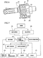
- a shift switch 79 is provided on a grip side of a left handle 77, for example.
- This shift switch 79 includes an up switch 81 and a down switch 83, for example, and is configured to change a shift position of the change gears from a neutral position to a first gear and the fastest sixth gear, for example, in an increasing or decreasing direction by manual operation of a driver.
- the grip side of the left handle 77 is also provided with an AMT switch 85, a turn signal 87, a horn 89, and a light switch 91.
- the AMT switch 85 is configured to switch a gear shift operation to be operated either in a semi-automatic mode or in a full-automatic mode.
- switching of the multistage shifting mechanism as well as of a clutch 93 is driven by unillustrated hydraulic mechanisms including motors, pumps, oil tanks, accumulators, and the like by use of the AMT mechanism 63.
- the clutch actuator 65 is provided with a stroke sensor (not shown) for detecting a stroke of the clutch 93 by detecting a position of the rod 73, for example, and the transmission 55 is provided with various sensors such as a car speed sensor or a shift position sensor.
- the clutch actuator 65 and the shift actuator 67 are driven by an engine controller 95. That is to say, a series of shifting operations including disconnection of the clutch 93, shifting of the change gears, and connection of the clutch 93 are operated automatically by given programs and other operation circuits stored in advance in the engine controller 95.
- the AMT mechanism 63 including the clutch actuator 65, the shift actuator 67, other components necessary for the AMT, and the like is located behind the cylinder block 47 of the engine unit 13 and above the transmission 55.
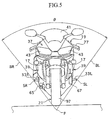
- the AMT mechanism 63 is located inside a bank angle ⁇ of the motorcycle 1 as shown in Fig. 5.
- the bank angle indicates an angle ⁇ formed between straight lines BL and BR, which are defined by connecting left and right parts of tread surfaces of tires 97 on the front wheel 21 and the rear wheel 29 to a point SL and a point SR representing tips of left and right steps 33L and 33R (a point P represents a intersection point of the straight lines BL and BR).
- the shift actuator 67 is located relatively below the motorcycle 1 on the left side in the traveling direction (on the right side in Fig. 5), however is located inside the bank angle ⁇ .
- the clutch actuator 65 is also located relatively below the motorcycle 1 on the right side in the traveling direction (on the left side in Fig. 5), however is located inside the bank angle ⁇ .
Landscapes
- Engineering & Computer Science (AREA)
- Mechanical Engineering (AREA)
- Hydraulic Clutches, Magnetic Clutches, Fluid Clutches, And Fluid Joints (AREA)
- Arrangement Of Transmissions (AREA)
- Arrangement Or Mounting Of Control Devices For Change-Speed Gearing (AREA)
- Gear-Shifting Mechanisms (AREA)
- Axle Suspensions And Sidecars For Cycles (AREA)
- Arrangement And Mounting Of Devices That Control Transmission Of Motive Force (AREA)
- Structure Of Transmissions (AREA)
- Arrangement Or Mounting Of Propulsion Units For Vehicles (AREA)
Abstract
Description
Claims (2)
- A motorcycle including a cylinder block of an engine, a crankcase located below this cylinder block, a transmission located behind this crankcase and provided with a multistage shifting mechanism having multistage change gears, a clutch for connecting/disconnecting transmission of rotation when shifting the change gears of this transmission, and an automatic transmission control device for automatically actuating this clutch and shifting the change gears of the transmission,
wherein the automatic transmission control device is located behind the cylinder block and above the transmission. - A motorcycle including a cylinder block of an engine, a crankcase located below this cylinder block, a transmission located behind this crankcase and provided with a multistage shifting mechanism having multistage change gears, a clutch for connecting/disconnecting transmission of rotation when shifting the change gears of this transmission, and an automatic transmission control device for automatically actuating this clutch and shifting the change gears of the transmission,
wherein the automatic transmission control device is located in a space between two left and right straight lines respectively connecting tread surfaces of a tire of the motorcycle and tips of left and right steps in a car width direction for allowing a driver to step on.
Applications Claiming Priority (3)
| Application Number | Priority Date | Filing Date | Title |
|---|---|---|---|
| JP2002127107A JP4253464B2 (en) | 2002-04-26 | 2002-04-26 | Motorcycle |
| JP2002127107 | 2002-04-26 | ||
| PCT/JP2003/005365 WO2003091059A1 (en) | 2002-04-26 | 2003-04-25 | Motorcycle |
Publications (3)
| Publication Number | Publication Date |
|---|---|
| EP1502801A1 true EP1502801A1 (en) | 2005-02-02 |
| EP1502801A4 EP1502801A4 (en) | 2006-06-07 |
| EP1502801B1 EP1502801B1 (en) | 2008-10-08 |
Family
ID=29267635
Family Applications (1)
| Application Number | Title | Priority Date | Filing Date |
|---|---|---|---|
| EP03719209A Expired - Lifetime EP1502801B1 (en) | 2002-04-26 | 2003-04-25 | Motorcycle |
Country Status (10)
| Country | Link |
|---|---|
| US (1) | US7174984B2 (en) |
| EP (1) | EP1502801B1 (en) |
| JP (1) | JP4253464B2 (en) |
| CN (2) | CN101327738B (en) |
| AT (1) | ATE410327T1 (en) |
| AU (1) | AU2003235826A1 (en) |
| DE (1) | DE60323963D1 (en) |
| ES (1) | ES2314194T3 (en) |
| TW (1) | TWI254011B (en) |
| WO (1) | WO2003091059A1 (en) |
Cited By (4)
| Publication number | Priority date | Publication date | Assignee | Title |
|---|---|---|---|---|
| US7380630B2 (en) | 2004-10-25 | 2008-06-03 | Yamaha Hatsudoki Kabushiki Kaisha | Shift actuator mounting arrangement for motorcycle |
| EP2042777A1 (en) * | 2007-09-29 | 2009-04-01 | Honda Motor Co., Ltd. | Structure for disposing a shift actuator in a power unit for saddle-ride type vehicle |
| CN101398058B (en) * | 2007-09-29 | 2011-09-14 | 本田技研工业株式会社 | Structure for disposing shift actuator in power unit for saddle-ride vehicle |
| EP4471298A1 (en) * | 2023-06-02 | 2024-12-04 | Yamaha Hatsudoki Kabushiki Kaisha | Straddled vehicle equipped with parallel multicylinder engine |
Families Citing this family (24)
| Publication number | Priority date | Publication date | Assignee | Title |
|---|---|---|---|---|
| JP4606075B2 (en) * | 2004-07-01 | 2011-01-05 | ヤマハ発動機株式会社 | Power transmission system controller for saddle-ride type vehicles |
| JP4476720B2 (en) * | 2004-07-02 | 2010-06-09 | 本田技研工業株式会社 | Fender structure for motorcycles |
| JP4936805B2 (en) * | 2004-10-21 | 2012-05-23 | ヤマハ発動機株式会社 | Saddle riding vehicle |
| EP1650120A3 (en) | 2004-10-21 | 2008-11-26 | Yamaha Hatsudoki Kabushiki Kaisha | Motorcycle |
| JP4936693B2 (en) * | 2004-10-21 | 2012-05-23 | ヤマハ発動機株式会社 | Saddle riding vehicle |
| CN100415593C (en) * | 2004-10-21 | 2008-09-03 | 雅马哈发动机株式会社 | straddle vehicle |
| US7367420B1 (en) * | 2004-12-13 | 2008-05-06 | Polaris Industries Inc. | All terrain vehicle (ATV) having a rider interface for electronic or mechanical shifting |
| JP4499620B2 (en) * | 2005-06-16 | 2010-07-07 | 本田技研工業株式会社 | Speed change operation device for vehicle |
| JP2007198586A (en) | 2005-12-28 | 2007-08-09 | Yamaha Motor Co Ltd | Saddle riding vehicle |
| JP2007198587A (en) | 2005-12-28 | 2007-08-09 | Yamaha Motor Co Ltd | Shift actuator, vehicle equipped with the same, and shift actuator assembly method |
| JP4620612B2 (en) * | 2006-03-07 | 2011-01-26 | 耕次郎 原田 | Hydraulic clutch device linked with motorcycle return-type transmission |
| JP4914677B2 (en) * | 2006-08-30 | 2012-04-11 | 本田技研工業株式会社 | Twin clutch transmission in a vehicle power unit |
| JP5047574B2 (en) * | 2006-09-28 | 2012-10-10 | 本田技研工業株式会社 | Clutch device |
| JP5013813B2 (en) | 2006-10-30 | 2012-08-29 | 本田技研工業株式会社 | Power unit for vehicle |
| JP5013815B2 (en) * | 2006-10-31 | 2012-08-29 | 本田技研工業株式会社 | Power unit for vehicle |
| JP4358222B2 (en) * | 2006-11-30 | 2009-11-04 | 本田技研工業株式会社 | Engine with clutch actuator |
| JP5123642B2 (en) * | 2007-10-31 | 2013-01-23 | 本田技研工業株式会社 | Small saddle-ride type vehicle |
| JP5013442B2 (en) * | 2010-08-16 | 2012-08-29 | ヤマハ発動機株式会社 | Motorcycle |
| TWI453350B (en) * | 2011-11-28 | 2014-09-21 | Kwang Yang Motor Co | Vehicle transmission |
| EP2797808A2 (en) * | 2011-12-27 | 2014-11-05 | TVS Motor Company Limited | Vehicle |
| JP6115369B2 (en) * | 2013-07-18 | 2017-04-19 | スズキ株式会社 | Automatic transmission equipment for motorcycles |
| JP6840956B2 (en) * | 2016-08-15 | 2021-03-10 | スズキ株式会社 | Motorcycle |
| JP6834240B2 (en) * | 2016-08-15 | 2021-02-24 | スズキ株式会社 | Motorcycle |
| JP6779953B2 (en) * | 2018-09-27 | 2020-11-04 | 本田技研工業株式会社 | Engine superstructure of saddle-riding vehicle |
Family Cites Families (18)
| Publication number | Priority date | Publication date | Assignee | Title |
|---|---|---|---|---|
| US3894442A (en) * | 1974-04-15 | 1975-07-15 | Ray Hembree | Semi-automatic electric gear shifting apparatus for a motorcycle |
| DE2903742C2 (en) * | 1979-02-01 | 1981-06-19 | Bayerische Motoren Werke AG, 8000 München | Engine arrangement for motorcycles |
| JPH0514043Y2 (en) | 1984-10-31 | 1993-04-14 | ||
| US5299652A (en) * | 1992-11-17 | 1994-04-05 | Bevins John P | Motorcycle controls for physically challenged rider |
| JPH1159511A (en) * | 1997-08-13 | 1999-03-02 | Honda Motor Co Ltd | Vehicle safety equipment with trailer |
| JP3992798B2 (en) | 1997-08-28 | 2007-10-17 | ヤマハ発動機株式会社 | Engine suspension system for motorcycles |
| JP4202446B2 (en) * | 1997-09-14 | 2008-12-24 | 本田技研工業株式会社 | Hybrid unit power unit arrangement structure |
| JP3816210B2 (en) * | 1997-09-30 | 2006-08-30 | 本田技研工業株式会社 | Body structure of a low-floor motorcycle |
| EP0911253B1 (en) * | 1997-10-21 | 2003-11-26 | Honda Giken Kogyo Kabushiki Kaisha | Power unit for vehicle |
| CA2250978A1 (en) * | 1997-10-25 | 1999-04-25 | Bombardier Inc. | Transmission system for a straddle type vehicle |
| CN2316232Y (en) * | 1998-01-08 | 1999-04-28 | 任伟峰 | Electric gearshift for motorcycle |
| US6131682A (en) * | 1998-12-22 | 2000-10-17 | Walker; Dale | Electric solenoid shifter |
| JP2001124203A (en) | 1999-10-22 | 2001-05-11 | Honda Motor Co Ltd | Change device for vehicle transmission |
| US6533056B1 (en) * | 2000-04-25 | 2003-03-18 | Bud A. Maimone | Motorcycle automatic clutch with manual release |
| JP3829585B2 (en) * | 2000-05-30 | 2006-10-04 | スズキ株式会社 | Motorcycle power unit |
| JP4075296B2 (en) * | 2000-08-30 | 2008-04-16 | スズキ株式会社 | Scooter type motorcycle |
| JP2002067741A (en) * | 2000-09-01 | 2002-03-08 | Yamaha Motor Co Ltd | Transmission control device for motorcycle |
| US6705446B2 (en) * | 2001-06-07 | 2004-03-16 | Drussel Wilfley Design, Llc | Automatic clutch with manual override control mechanism |
-
2002
- 2002-04-26 JP JP2002127107A patent/JP4253464B2/en not_active Expired - Lifetime
-
2003
- 2003-04-25 ES ES03719209T patent/ES2314194T3/en not_active Expired - Lifetime
- 2003-04-25 US US10/511,887 patent/US7174984B2/en not_active Expired - Lifetime
- 2003-04-25 DE DE60323963T patent/DE60323963D1/en not_active Expired - Lifetime
- 2003-04-25 CN CN2008101281971A patent/CN101327738B/en not_active Expired - Lifetime
- 2003-04-25 EP EP03719209A patent/EP1502801B1/en not_active Expired - Lifetime
- 2003-04-25 AU AU2003235826A patent/AU2003235826A1/en not_active Abandoned
- 2003-04-25 CN CNB038082926A patent/CN100450812C/en not_active Expired - Lifetime
- 2003-04-25 WO PCT/JP2003/005365 patent/WO2003091059A1/en not_active Ceased
- 2003-04-25 AT AT03719209T patent/ATE410327T1/en not_active IP Right Cessation
- 2003-04-25 TW TW092109724A patent/TWI254011B/en not_active IP Right Cessation
Cited By (5)
| Publication number | Priority date | Publication date | Assignee | Title |
|---|---|---|---|---|
| US7380630B2 (en) | 2004-10-25 | 2008-06-03 | Yamaha Hatsudoki Kabushiki Kaisha | Shift actuator mounting arrangement for motorcycle |
| EP2042777A1 (en) * | 2007-09-29 | 2009-04-01 | Honda Motor Co., Ltd. | Structure for disposing a shift actuator in a power unit for saddle-ride type vehicle |
| CN101398058B (en) * | 2007-09-29 | 2011-09-14 | 本田技研工业株式会社 | Structure for disposing shift actuator in power unit for saddle-ride vehicle |
| US8245588B2 (en) | 2007-09-29 | 2012-08-21 | Honda Motor Co., Ltd. | Structure for disposing shift actuator in power unit for saddle-ride vehicle |
| EP4471298A1 (en) * | 2023-06-02 | 2024-12-04 | Yamaha Hatsudoki Kabushiki Kaisha | Straddled vehicle equipped with parallel multicylinder engine |
Also Published As
| Publication number | Publication date |
|---|---|
| TWI254011B (en) | 2006-05-01 |
| US7174984B2 (en) | 2007-02-13 |
| EP1502801A4 (en) | 2006-06-07 |
| CN101327738A (en) | 2008-12-24 |
| CN1655961A (en) | 2005-08-17 |
| ATE410327T1 (en) | 2008-10-15 |
| CN100450812C (en) | 2009-01-14 |
| JP2003320861A (en) | 2003-11-11 |
| JP4253464B2 (en) | 2009-04-15 |
| DE60323963D1 (en) | 2008-11-20 |
| CN101327738B (en) | 2011-12-28 |
| WO2003091059A1 (en) | 2003-11-06 |
| TW200306927A (en) | 2003-12-01 |
| EP1502801B1 (en) | 2008-10-08 |
| ES2314194T3 (en) | 2009-03-16 |
| US20050217915A1 (en) | 2005-10-06 |
| AU2003235826A1 (en) | 2003-11-10 |
Similar Documents
| Publication | Publication Date | Title |
|---|---|---|
| US7174984B2 (en) | Motorcycle | |
| US7490687B2 (en) | Control method for transmission for motorcycle | |
| JP5053159B2 (en) | Saddle riding vehicle | |
| CN101190656B (en) | Engine including speed-change actuator | |
| US7594495B2 (en) | Electronic throttle valve control system and two-wheeled motor vehicle | |
| JP5914444B2 (en) | Vehicle transmission | |
| JP2010261385A (en) | Electronically controlled throttle valve controller | |
| JP2003341376A (en) | Transmission control device | |
| JP2020006771A (en) | Operation part structure of saddle-ride type vehicle and saddle-ride type vehicle | |
| JP6526142B2 (en) | Arrangement structure of gear position detection sensor | |
| EP3992072B1 (en) | Straddled vehicle shift pedal sensor | |
| EP2299095A2 (en) | Engine control system for a vehicle | |
| JP2017219086A (en) | Vehicle transmission system | |
| JP2019065875A (en) | Gear position detection device | |
| US20060035747A1 (en) | Electric multi-stage transmission | |
| JP7059442B2 (en) | Clutch control device and clutch control method for saddle-mounted vehicles | |
| US20190300121A1 (en) | Saddle-type vehicle | |
| JP4887088B2 (en) | Shift switch handle switch | |
| JPS6220936A (en) | Speed change gear for riding type vehicle | |
| JP4807788B2 (en) | Instrument display | |
| JP7725709B2 (en) | Saddle-type vehicle | |
| JP7073579B2 (en) | Clutch control device and clutch control method for saddle-mounted vehicles | |
| JP5363386B2 (en) | Work vehicle | |
| JPH08258618A (en) | Headlight lighting control device for motorcycles | |
| JP2026053091A (en) | Saddle-type vehicle |
Legal Events
| Date | Code | Title | Description |
|---|---|---|---|
| PUAI | Public reference made under article 153(3) epc to a published international application that has entered the european phase |
Free format text: ORIGINAL CODE: 0009012 |
|
| 17P | Request for examination filed |
Effective date: 20041117 |
|
| AK | Designated contracting states |
Kind code of ref document: A1 Designated state(s): AT BE BG CH CY CZ DE DK EE ES FI FR GB GR HU IE IT LI LU MC NL PT RO SE SI SK TR |
|
| AX | Request for extension of the european patent |
Extension state: AL LT LV MK |
|
| A4 | Supplementary search report drawn up and despatched |
Effective date: 20060425 |
|
| 17Q | First examination report despatched |
Effective date: 20060728 |
|
| GRAP | Despatch of communication of intention to grant a patent |
Free format text: ORIGINAL CODE: EPIDOSNIGR1 |
|
| GRAS | Grant fee paid |
Free format text: ORIGINAL CODE: EPIDOSNIGR3 |
|
| GRAA | (expected) grant |
Free format text: ORIGINAL CODE: 0009210 |
|
| AK | Designated contracting states |
Kind code of ref document: B1 Designated state(s): AT BE BG CH CY CZ DE DK EE ES FI FR GB GR HU IE IT LI LU MC NL PT RO SE SI SK TR |
|
| REG | Reference to a national code |
Ref country code: GB Ref legal event code: FG4D |
|
| REG | Reference to a national code |
Ref country code: CH Ref legal event code: EP |
|
| REG | Reference to a national code |
Ref country code: IE Ref legal event code: FG4D |
|
| REF | Corresponds to: |
Ref document number: 60323963 Country of ref document: DE Date of ref document: 20081120 Kind code of ref document: P |
|
| PG25 | Lapsed in a contracting state [announced via postgrant information from national office to epo] |
Ref country code: SI Free format text: LAPSE BECAUSE OF FAILURE TO SUBMIT A TRANSLATION OF THE DESCRIPTION OR TO PAY THE FEE WITHIN THE PRESCRIBED TIME-LIMIT Effective date: 20081008 |
|
| REG | Reference to a national code |
Ref country code: ES Ref legal event code: FG2A Ref document number: 2314194 Country of ref document: ES Kind code of ref document: T3 |
|
| NLV1 | Nl: lapsed or annulled due to failure to fulfill the requirements of art. 29p and 29m of the patents act | ||
| PG25 | Lapsed in a contracting state [announced via postgrant information from national office to epo] |
Ref country code: AT Free format text: LAPSE BECAUSE OF FAILURE TO SUBMIT A TRANSLATION OF THE DESCRIPTION OR TO PAY THE FEE WITHIN THE PRESCRIBED TIME-LIMIT Effective date: 20081008 Ref country code: BG Free format text: LAPSE BECAUSE OF FAILURE TO SUBMIT A TRANSLATION OF THE DESCRIPTION OR TO PAY THE FEE WITHIN THE PRESCRIBED TIME-LIMIT Effective date: 20090108 |
|
| PG25 | Lapsed in a contracting state [announced via postgrant information from national office to epo] |
Ref country code: PT Free format text: LAPSE BECAUSE OF FAILURE TO SUBMIT A TRANSLATION OF THE DESCRIPTION OR TO PAY THE FEE WITHIN THE PRESCRIBED TIME-LIMIT Effective date: 20090218 Ref country code: NL Free format text: LAPSE BECAUSE OF FAILURE TO SUBMIT A TRANSLATION OF THE DESCRIPTION OR TO PAY THE FEE WITHIN THE PRESCRIBED TIME-LIMIT Effective date: 20081008 Ref country code: FI Free format text: LAPSE BECAUSE OF FAILURE TO SUBMIT A TRANSLATION OF THE DESCRIPTION OR TO PAY THE FEE WITHIN THE PRESCRIBED TIME-LIMIT Effective date: 20081008 |
|
| PG25 | Lapsed in a contracting state [announced via postgrant information from national office to epo] |
Ref country code: RO Free format text: LAPSE BECAUSE OF FAILURE TO SUBMIT A TRANSLATION OF THE DESCRIPTION OR TO PAY THE FEE WITHIN THE PRESCRIBED TIME-LIMIT Effective date: 20081008 Ref country code: EE Free format text: LAPSE BECAUSE OF FAILURE TO SUBMIT A TRANSLATION OF THE DESCRIPTION OR TO PAY THE FEE WITHIN THE PRESCRIBED TIME-LIMIT Effective date: 20081008 Ref country code: BE Free format text: LAPSE BECAUSE OF FAILURE TO SUBMIT A TRANSLATION OF THE DESCRIPTION OR TO PAY THE FEE WITHIN THE PRESCRIBED TIME-LIMIT Effective date: 20081008 Ref country code: DK Free format text: LAPSE BECAUSE OF FAILURE TO SUBMIT A TRANSLATION OF THE DESCRIPTION OR TO PAY THE FEE WITHIN THE PRESCRIBED TIME-LIMIT Effective date: 20081008 |
|
| PLBE | No opposition filed within time limit |
Free format text: ORIGINAL CODE: 0009261 |
|
| STAA | Information on the status of an ep patent application or granted ep patent |
Free format text: STATUS: NO OPPOSITION FILED WITHIN TIME LIMIT |
|
| PG25 | Lapsed in a contracting state [announced via postgrant information from national office to epo] |
Ref country code: SE Free format text: LAPSE BECAUSE OF FAILURE TO SUBMIT A TRANSLATION OF THE DESCRIPTION OR TO PAY THE FEE WITHIN THE PRESCRIBED TIME-LIMIT Effective date: 20090108 Ref country code: CZ Free format text: LAPSE BECAUSE OF FAILURE TO SUBMIT A TRANSLATION OF THE DESCRIPTION OR TO PAY THE FEE WITHIN THE PRESCRIBED TIME-LIMIT Effective date: 20081008 |
|
| 26N | No opposition filed |
Effective date: 20090709 |
|
| PG25 | Lapsed in a contracting state [announced via postgrant information from national office to epo] |
Ref country code: SK Free format text: LAPSE BECAUSE OF FAILURE TO SUBMIT A TRANSLATION OF THE DESCRIPTION OR TO PAY THE FEE WITHIN THE PRESCRIBED TIME-LIMIT Effective date: 20081008 |
|
| REG | Reference to a national code |
Ref country code: CH Ref legal event code: PL |
|
| PG25 | Lapsed in a contracting state [announced via postgrant information from national office to epo] |
Ref country code: LI Free format text: LAPSE BECAUSE OF NON-PAYMENT OF DUE FEES Effective date: 20090430 Ref country code: CH Free format text: LAPSE BECAUSE OF NON-PAYMENT OF DUE FEES Effective date: 20090430 |
|
| REG | Reference to a national code |
Ref country code: IE Ref legal event code: MM4A |
|
| PG25 | Lapsed in a contracting state [announced via postgrant information from national office to epo] |
Ref country code: MC Free format text: LAPSE BECAUSE OF NON-PAYMENT OF DUE FEES Effective date: 20090430 Ref country code: IE Free format text: LAPSE BECAUSE OF NON-PAYMENT OF DUE FEES Effective date: 20090425 |
|
| PG25 | Lapsed in a contracting state [announced via postgrant information from national office to epo] |
Ref country code: GR Free format text: LAPSE BECAUSE OF FAILURE TO SUBMIT A TRANSLATION OF THE DESCRIPTION OR TO PAY THE FEE WITHIN THE PRESCRIBED TIME-LIMIT Effective date: 20090109 |
|
| PG25 | Lapsed in a contracting state [announced via postgrant information from national office to epo] |
Ref country code: LU Free format text: LAPSE BECAUSE OF NON-PAYMENT OF DUE FEES Effective date: 20090425 |
|
| PG25 | Lapsed in a contracting state [announced via postgrant information from national office to epo] |
Ref country code: HU Free format text: LAPSE BECAUSE OF FAILURE TO SUBMIT A TRANSLATION OF THE DESCRIPTION OR TO PAY THE FEE WITHIN THE PRESCRIBED TIME-LIMIT Effective date: 20090409 |
|
| PG25 | Lapsed in a contracting state [announced via postgrant information from national office to epo] |
Ref country code: TR Free format text: LAPSE BECAUSE OF FAILURE TO SUBMIT A TRANSLATION OF THE DESCRIPTION OR TO PAY THE FEE WITHIN THE PRESCRIBED TIME-LIMIT Effective date: 20081008 |
|
| PG25 | Lapsed in a contracting state [announced via postgrant information from national office to epo] |
Ref country code: CY Free format text: LAPSE BECAUSE OF FAILURE TO SUBMIT A TRANSLATION OF THE DESCRIPTION OR TO PAY THE FEE WITHIN THE PRESCRIBED TIME-LIMIT Effective date: 20081008 |
|
| REG | Reference to a national code |
Ref country code: FR Ref legal event code: PLFP Year of fee payment: 14 |
|
| REG | Reference to a national code |
Ref country code: FR Ref legal event code: PLFP Year of fee payment: 15 |
|
| REG | Reference to a national code |
Ref country code: FR Ref legal event code: PLFP Year of fee payment: 16 |
|
| PGFP | Annual fee paid to national office [announced via postgrant information from national office to epo] |
Ref country code: IT Payment date: 20220420 Year of fee payment: 20 Ref country code: GB Payment date: 20220420 Year of fee payment: 20 Ref country code: FR Payment date: 20220420 Year of fee payment: 20 Ref country code: ES Payment date: 20220629 Year of fee payment: 20 Ref country code: DE Payment date: 20220420 Year of fee payment: 20 |
|
| REG | Reference to a national code |
Ref country code: DE Ref legal event code: R071 Ref document number: 60323963 Country of ref document: DE |
|
| REG | Reference to a national code |
Ref country code: ES Ref legal event code: FD2A Effective date: 20230504 |
|
| REG | Reference to a national code |
Ref country code: GB Ref legal event code: PE20 Expiry date: 20230424 |
|
| PG25 | Lapsed in a contracting state [announced via postgrant information from national office to epo] |
Ref country code: ES Free format text: LAPSE BECAUSE OF EXPIRATION OF PROTECTION Effective date: 20230426 |
|
| PG25 | Lapsed in a contracting state [announced via postgrant information from national office to epo] |
Ref country code: GB Free format text: LAPSE BECAUSE OF EXPIRATION OF PROTECTION Effective date: 20230424 |