CN101398058B - Structure for disposing shift actuator in power unit for saddle-ride vehicle - Google Patents
Structure for disposing shift actuator in power unit for saddle-ride vehicle Download PDFInfo
- Publication number
- CN101398058B CN101398058B CN200810168708.2A CN200810168708A CN101398058B CN 101398058 B CN101398058 B CN 101398058B CN 200810168708 A CN200810168708 A CN 200810168708A CN 101398058 B CN101398058 B CN 101398058B
- Authority
- CN
- China
- Prior art keywords
- gear
- crankcase
- mentioned
- shift actuator
- clutch
- Prior art date
- Legal status (The legal status is an assumption and is not a legal conclusion. Google has not performed a legal analysis and makes no representation as to the accuracy of the status listed.)
- Expired - Fee Related
Links
- 230000009471 action Effects 0.000 claims abstract description 26
- 230000009467 reduction Effects 0.000 claims description 27
- 230000015572 biosynthetic process Effects 0.000 claims description 8
- 230000007246 mechanism Effects 0.000 abstract description 39
- 230000005540 biological transmission Effects 0.000 abstract description 17
- 238000012423 maintenance Methods 0.000 abstract description 2
- 238000005202 decontamination Methods 0.000 description 12
- 230000003588 decontaminative effect Effects 0.000 description 12
- 230000008859 change Effects 0.000 description 11
- XLYOFNOQVPJJNP-UHFFFAOYSA-N water Substances O XLYOFNOQVPJJNP-UHFFFAOYSA-N 0.000 description 10
- 230000000694 effects Effects 0.000 description 9
- 230000006835 compression Effects 0.000 description 8
- 238000007906 compression Methods 0.000 description 8
- 239000011148 porous material Substances 0.000 description 8
- 239000003638 chemical reducing agent Substances 0.000 description 7
- 238000005755 formation reaction Methods 0.000 description 7
- 239000002516 radical scavenger Substances 0.000 description 6
- 238000001914 filtration Methods 0.000 description 5
- 239000004519 grease Substances 0.000 description 5
- 230000033001 locomotion Effects 0.000 description 5
- 239000000463 material Substances 0.000 description 5
- 230000003321 amplification Effects 0.000 description 4
- 238000003199 nucleic acid amplification method Methods 0.000 description 4
- 238000003825 pressing Methods 0.000 description 4
- 238000001816 cooling Methods 0.000 description 3
- 239000007788 liquid Substances 0.000 description 3
- 230000007935 neutral effect Effects 0.000 description 3
- 244000144985 peep Species 0.000 description 3
- 238000013016 damping Methods 0.000 description 2
- 238000001514 detection method Methods 0.000 description 2
- 238000010586 diagram Methods 0.000 description 2
- 230000004075 alteration Effects 0.000 description 1
- 230000004069 differentiation Effects 0.000 description 1
- ZZUFCTLCJUWOSV-UHFFFAOYSA-N furosemide Chemical compound C1=C(Cl)C(S(=O)(=O)N)=CC(C(O)=O)=C1NCC1=CC=CO1 ZZUFCTLCJUWOSV-UHFFFAOYSA-N 0.000 description 1
- BGOFCVIGEYGEOF-UJPOAAIJSA-N helicin Chemical compound O[C@@H]1[C@@H](O)[C@H](O)[C@@H](CO)O[C@H]1OC1=CC=CC=C1C=O BGOFCVIGEYGEOF-UJPOAAIJSA-N 0.000 description 1
- 230000006872 improvement Effects 0.000 description 1
- 238000009434 installation Methods 0.000 description 1
- 230000013011 mating Effects 0.000 description 1
- 238000000034 method Methods 0.000 description 1
- 238000000746 purification Methods 0.000 description 1
- 238000005096 rolling process Methods 0.000 description 1
- 238000009987 spinning Methods 0.000 description 1
- 239000007858 starting material Substances 0.000 description 1
- 238000003860 storage Methods 0.000 description 1
Images


Classifications
-
- F—MECHANICAL ENGINEERING; LIGHTING; HEATING; WEAPONS; BLASTING
- F16—ENGINEERING ELEMENTS AND UNITS; GENERAL MEASURES FOR PRODUCING AND MAINTAINING EFFECTIVE FUNCTIONING OF MACHINES OR INSTALLATIONS; THERMAL INSULATION IN GENERAL
- F16H—GEARING
- F16H61/00—Control functions within control units of change-speed- or reversing-gearings for conveying rotary motion ; Control of exclusively fluid gearing, friction gearing, gearings with endless flexible members or other particular types of gearing
- F16H61/26—Generation or transmission of movements for final actuating mechanisms
- F16H61/28—Generation or transmission of movements for final actuating mechanisms with at least one movement of the final actuating mechanism being caused by a non-mechanical force, e.g. power-assisted
-
- F—MECHANICAL ENGINEERING; LIGHTING; HEATING; WEAPONS; BLASTING
- F16—ENGINEERING ELEMENTS AND UNITS; GENERAL MEASURES FOR PRODUCING AND MAINTAINING EFFECTIVE FUNCTIONING OF MACHINES OR INSTALLATIONS; THERMAL INSULATION IN GENERAL
- F16H—GEARING
- F16H57/00—General details of gearing
- F16H57/02—Gearboxes; Mounting gearing therein
- F16H2057/0203—Gearboxes; Mounting gearing therein the gearbox is associated or combined with a crank case of an engine
-
- F—MECHANICAL ENGINEERING; LIGHTING; HEATING; WEAPONS; BLASTING
- F16—ENGINEERING ELEMENTS AND UNITS; GENERAL MEASURES FOR PRODUCING AND MAINTAINING EFFECTIVE FUNCTIONING OF MACHINES OR INSTALLATIONS; THERMAL INSULATION IN GENERAL
- F16H—GEARING
- F16H57/00—General details of gearing
- F16H57/02—Gearboxes; Mounting gearing therein
- F16H2057/02039—Gearboxes for particular applications
- F16H2057/02043—Gearboxes for particular applications for vehicle transmissions
- F16H2057/02065—Gearboxes for particular applications for vehicle transmissions for motorcycles or squads
-
- F—MECHANICAL ENGINEERING; LIGHTING; HEATING; WEAPONS; BLASTING
- F16—ENGINEERING ELEMENTS AND UNITS; GENERAL MEASURES FOR PRODUCING AND MAINTAINING EFFECTIVE FUNCTIONING OF MACHINES OR INSTALLATIONS; THERMAL INSULATION IN GENERAL
- F16H—GEARING
- F16H3/00—Toothed gearings for conveying rotary motion with variable gear ratio or for reversing rotary motion
- F16H3/006—Toothed gearings for conveying rotary motion with variable gear ratio or for reversing rotary motion power being selectively transmitted by either one of the parallel flow paths
-
- Y—GENERAL TAGGING OF NEW TECHNOLOGICAL DEVELOPMENTS; GENERAL TAGGING OF CROSS-SECTIONAL TECHNOLOGIES SPANNING OVER SEVERAL SECTIONS OF THE IPC; TECHNICAL SUBJECTS COVERED BY FORMER USPC CROSS-REFERENCE ART COLLECTIONS [XRACs] AND DIGESTS
- Y10—TECHNICAL SUBJECTS COVERED BY FORMER USPC
- Y10T—TECHNICAL SUBJECTS COVERED BY FORMER US CLASSIFICATION
- Y10T74/00—Machine element or mechanism
- Y10T74/19—Gearing
- Y10T74/19219—Interchangeably locked
- Y10T74/19251—Control mechanism
-
- Y—GENERAL TAGGING OF NEW TECHNOLOGICAL DEVELOPMENTS; GENERAL TAGGING OF CROSS-SECTIONAL TECHNOLOGIES SPANNING OVER SEVERAL SECTIONS OF THE IPC; TECHNICAL SUBJECTS COVERED BY FORMER USPC CROSS-REFERENCE ART COLLECTIONS [XRACs] AND DIGESTS
- Y10—TECHNICAL SUBJECTS COVERED BY FORMER USPC
- Y10T—TECHNICAL SUBJECTS COVERED BY FORMER US CLASSIFICATION
- Y10T74/00—Machine element or mechanism
- Y10T74/21—Elements
- Y10T74/2186—Gear casings
Abstract
The invention provides a structure for disposing a shift actuator in a power unit for a saddle-ride type vehicle; a transmission mechanism disposed in the course of power transmission between a crankshaft and a drive wheel is installed in a crankcase, and a shift actuator to drive and control the gear-shifting action of the transmission mechanism is disposed in the engine main body. The shift actuator is attached so that a high degree of freedom in the layout is guaranteed for the functional parts disposed around the crankcase and the amount of outward protrusion from the crankcase is reduced and the maintenance work is improved. The shift actuator (181) is attached to a side surface of the crankcase (35) with the operational axis of the shift actuator being placed in a plane that is orthogonal to the axial direction of the transmission mechanism.
Description
Technical field
The present invention relates to rotating supporting crankshaft freely and constituting the gear in the power transfer path be located at that the rotating power of accommodating in the crankcase of a part of engine main body described bent axle passes to driving wheel, and on above-mentioned engine main body, set the arrangement of shift actuator of power unit for saddle-ride vehicle of shift actuator of the gear shifting operation of the described gear of drive controlling, particularly relate to the improvement of the arrangement of shift actuator.
Background technique
Known in the patent documentation 1 have a following structure: set the shift actuator that the gear shifting operation of the gear that is contained in crankcase is carried out drive controlling on the crankcase of the power unit that is equipped on two-wheeled motorcycle.
Patent documentation 1: the spy opens clear 63-125490 communique
But as disclosed in the above-mentioned patent documentation 1, on crankcase in the structure of configuration shift actuator, it is restricted that air inlet system, containing box, storage battery and the vehicle seat etc. that are disposed at the crankcase top constitute the laying degrees of freedom of functional part of two-wheeled motorcycle.
Summary of the invention
The present invention constitutes in view of such situation, its purpose is, a kind of arrangement of shift actuator of power unit for saddle-ride vehicle is provided, configurable shift actuator, not only improving the degrees of freedom in the design be disposed at the functional part around the crankcase, and suppress from crankcase laterally overhang and improve maintainability.
For achieving the above object, first aspect present invention provides a kind of arrangement of shift actuator of power unit for saddle-ride vehicle, rotate bent axle freely and constituting the gear in the power transfer path of being arranged on that the rotating power of accommodating in the crankcase of a part of engine main body described bent axle passes to driving wheel, and the shift actuator of the gear shifting operation of the described gear of drive controlling is equipped on the described engine main body, it is characterized in that described shift actuator is installed in the side of described crankcase according to the mode in the axle direction plane orthogonal that its action axis is configured in described gear.
In addition, second aspect present invention is on the basis of first aspect, the arrangement of the shift actuator of power unit for saddle-ride vehicle is provided, it is characterized in that, the axle head of output shaft that constitutes the part of described gear according to the rotating power output that will pass to described gear from described bent axle to the mode of described driven wheel side is installed on a side of described crankcase freely by dismounting cover covers, and with described shift actuator according to the top that is positioned at described cover and be installed on the described side of described crankcase than outer end mode more in the inner part along the described cover of the axis of described output shaft.
Third aspect present invention first or the basis of second aspect on, the arrangement of the shift actuator of power unit for saddle-ride vehicle is provided, it is characterized in that, the generating hood of formation being accommodated the generator containing room of the generator that is connected with described bent axle is installed on the described side of described crankcase, and described shift actuator is installed on the described side of described crankcase along the outer end mode more in the inner part of the described generating hood of the axis of described bent axle according to rear that is positioned at described generating hood and ratio.
In addition, fourth aspect present invention is on the basis of the third aspect, the arrangement of the shift actuator of power unit for saddle-ride vehicle is provided, it is characterized in that, described shift actuator makes its action axis be installed on the described side of described crankcase obliquely at above-below direction.
In addition, embodiment's gear shift 103 is corresponding with gear of the present invention, embodiment's jack shaft 107 is corresponding with output shaft of the present invention, embodiment's first gear cover 116 and second gear cover 117 are corresponding with cover of the present invention, embodiment's gearshift driving motor 181 is corresponding with shift actuator of the present invention, and embodiment's trailing wheel WR is corresponding with driving wheel of the present invention.
According to first aspect present invention, because shift actuator is installed in the side at crankcase, so can improve the degrees of freedom in the design that is disposed at crankcase functional part on every side, and the access of the lateral direction shift actuator of ultromotivity unit is easy, can improve the maintainability of shift actuator.In addition, because the action axis of shift actuator is configured in the plane orthogonal of axis of the gear in the crankcase, therefore, although shift actuator has been installed, but still can suppress shift actuator from crankcase overhang laterally in the described side of crankcase with doing one's utmost.
In addition; according to second aspect present invention; the axle head of output shaft that constitutes the part of gear is covered; according to be positioned at dismounting be installed on freely crankcase described side cover the top and shift actuator is installed on a side of crankcase than outer end mode more in the inner part along the described cover of the axis of output shaft; therefore; can not be subjected to influence by cover protection shift actuator from the slungshot of below and muddy water etc.; do not need to be used to protect the special-purpose member of shift actuator, can reduce number of components.And, because as long as around the gear shift actuator, be provided for installing the boss etc. of safety cover,, can improve miscellaneous part degrees of freedom in design so there is not the miscellaneous part that the causes restriction in design of boss etc.
According to third aspect present invention, actuator be positioned at the generating hood of the described side of crankcase installing the rear and than along the outer end of the generating hood of the axis of bent axle more in the inner part, therefore, can apply flexibly effectively from the outstanding generating hood space on every side of the left surface of crankcase and dispose the gear shift actuator, by configuration gear shift actuator, can prevent that power unit from maximizing in the direction along the axis of bent axle.And, can not be subjected to influence by generating hood protection shift actuator from the slungshot in the place ahead and muddy water etc., do not need to be used to protect the special-purpose member of shift actuator, can reduce number of components.And, because as long as around the gear shift actuator, be provided for installing the boss etc. of safety cover,, can improve miscellaneous part degrees of freedom in design so there is not the miscellaneous part that the causes restriction in design of boss etc.
In addition, according to fourth aspect present invention, the action axis that is used for shift actuator tilts at above-below direction, so when the dismounting operation of carrying out shift actuator, the generating hood that is positioned at the place ahead does not become obstacle, therefore can improve maintainability.
Description of drawings
Fig. 1 is the left side view of two-wheeled motorcycle;
Fig. 2 is the left side view of power unit;
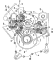
Fig. 3 is the right side view of power unit;
Fig. 4 is the 4-4 line sectional view of Fig. 2;
Fig. 5 is the 5-5 line sectional view of Fig. 4;
Fig. 6 is the sectional view corresponding with Fig. 5 on cylinder side side, rear portion;
Fig. 7 is the major component amplification view of Fig. 6;
Fig. 8 is the longitudinal section of gear shift and clutch device;
Fig. 9 is the major component enlarged view of Fig. 8;
Figure 10 is the 10-10 line amplification view of Fig. 2;
Figure 11 is the 11-11 line sectional view of Figure 10;
Figure 12 is the system diagram of the formation of expression oil pressure system;
Figure 13 is the major component enlarged view of Fig. 3;
Figure 14 is the 14-14 line sectional view of Figure 13;
Figure 15 be Figure 13 15 to view.
Symbol description
33 engine main bodies
35 crankcases
36 bent axles
84 generators
87 generating hoods
88 generator containing rooms
107 jack shafts as output shaft
103 gear shifts as gear
116 first gear covers as cover
117 second gear covers as cover
181 gearshift driving motors as shift actuator
The P power unit
WR is as the trailing wheel of driving wheel
Embodiment
Below, based on one embodiment of the invention explanation embodiments of the present invention shown in the drawings.
Fig. 1~Figure 15 represents one embodiment of the invention, Fig. 1 is the left side view of two-wheeled motorcycle, Fig. 2 is the left side view of power unit, Fig. 3 is the right side view of power unit, Fig. 4 is the 4-4 line sectional view of Fig. 2, Fig. 5 is the 5-5 line sectional view of Fig. 4, Fig. 6 is the sectional view corresponding with Fig. 5 on cylinder side side, rear portion, Fig. 7 is the major component amplification view of Fig. 6, Fig. 8 is the longitudinal section of gear shift and clutch device, Fig. 9 is the major component enlarged view of Fig. 8, and Figure 10 is the 10-10 line amplification view of Fig. 2, and Figure 11 is the 11-11 line sectional view of Figure 10, Figure 12 is the system diagram of the formation of expression oil pressure system, Figure 13 is the major component enlarged view of Fig. 3, and Figure 14 is the 14-14 line sectional view of Figure 13, Figure 15 be Figure 13 15 to view.
At first, among Fig. 1, Straddle-type vehicle is that the vehicle frame F of two-wheeled motorcycle has: can turn to twelve Earthly Branches honour front-wheel WF carry out the head pipe 26 of the front fork 25 of axle supporting, certainly the pairing left and right body frame 27 that extends down backward of this pipe 26, be connected with in the rear portion of two body frames 27 and the pairing left and right pivot plate 28 that extends downwards, trailing wheel W axle is bearing in the rear portion that front end is supported on the swing arm 29 of pivot plate 28 swingably.And, between the front portion of the bottom of above-mentioned pivot plate 28 and above-mentioned swing arm 29, connecting rod 30 is set, between the top of above-mentioned pivot plate 28 and above-mentioned connecting rod 30, damper unit 31 is set.
Be hung with the power unit P that is made of motor E and speed changer M on above-mentioned body frame 27 and pivot plate 28, the live axle 32 that the rotating power from above-mentioned speed changer M output of this power unit P extends via the front and back, edge is delivered to above-mentioned trailing wheel WR.
On the engine main body 33 of above-mentioned motor E or vehicle frame F, side support 34 is installed, among this embodiment, at the bottom of the left side of above-mentioned vehicle frame F pivot plate 28 installation side support 34.Therefore, side support 34 is being opened when carrying out Parking, two-wheeled motorcycle becomes the state that is tilted to the left side.
Among Fig. 2 and Fig. 3, the engine main body 33 of above-mentioned motor E has with the state that carries to two-wheeled motorcycle and is positioned at the anterior bank BF in the place ahead and is positioned at the rear portion bank BR by the rear than this front portion bank BF, constitute the V-type water-cooled, with the common crankcase 35 of two bank BF, BR on rotate and support freely along the bent axle 36 of the left and right directions of two-wheeled motorcycle.
Crankcase 35 is by constituting upper tank halfbody 35a and lower tank halfbody 35b combination, form front portion and rear portion cylinder block 38F, 38R according to the mode that becomes the V font on upper tank halfbody 35a, the axis of above-mentioned bent axle 36 disposes on the junction plane 37 of above-mentioned upper tank halfbody 35a and above-mentioned lower tank halfbody 35b.
Anterior bank BF is made of above-mentioned cylinder block 38F, the front cylinder head 39F that combines with anterior cylinder block 38F, the front cylinder head cover 40F that combines with front cylinder head 39F, rear portion bank BR is made of rear portion cylinder block 38R, the rear portion cylinder head 39R that combines with rear portion cylinder block 38R, the rear portion valve mechanism cover 40R that combines with rear portion cylinder head 39R, in the bottom of above-mentioned crankcase 35 in conjunction with oil pan 41.
Forwardly be formed with on the cylinder block 38F at the axial direction of above-mentioned bent axle 36 two cylinder barrels 42 arranged side by side, anterior cylinder block 38F combines with crankcase 35 according to the mode that the state that hangs to vehicle frame F with engine main body 33 tilts the axis of above-mentioned cylinder barrel 42 forward.In addition, be formed with on the cylinder block 39R of rear portion at the axial direction of above-mentioned bent axle 36 two cylinder barrels 42 arranged side by side, rear portion cylinder barrel 39R combines with crankcase 35 according to the mode that the state that hangs to vehicle frame F with engine main body 33 tilts the axis of each cylinder barrel 42 backward.And, distinguish chimeric slidably piston 43 and distinguish chimeric slidably piston 43 and above-mentioned 35 common connections of bent axle with two cylinder barrels 42 of anterior bank BF with two cylinder barrels 42 of rear portion bank BR.
Among Fig. 4 and Fig. 5, forwardly on the cylinder head 39F, each of each cylinder barrel 42 is set each intake valve 44, its by each a pair of valve spring 46 to closing the valve direction application of force can carry out on-off action, simultaneously, set each a pair of exhaust valve 45, its by valve spring 47 to closing the valve direction application of force can carry out on-off action.These intake valves 44 and exhaust valve 45 by anterior bank 48F by driven for opening and closing.
Anterior cylinder side side valve mechanism 48F possesses: have the axis parallel with above-mentioned bent axle 36, be rotated and be bearing in freely on the front cylinder head 39F, and be disposed at the camshaft 49 of the top of intake valve 44; Be installed on this camshaft 49 a plurality of (among this embodiment being four) the air inlet side cams 50 that are provided with and 44 of intake valves and be embedded in air inlet side valve tappet 51 on the front cylinder head 39F slidably; One end have be located at above-mentioned camshaft 49 on a plurality of (among this embodiment being four) exhaust side cams 52 twist the Rocker arm 55 that closes with the tappet screw 54 of the upper end butt of the bar 45a of each exhaust valve 45 with rolling the roller 53 that contact and the other end can regulate advance and retreat position; Rocker arm 55 has the axis parallel with above-mentioned camshaft 49, supports swingably in the pitman arm shaft 56 of front cylinder head 39F by fixed configurations.
Among Fig. 6, on the cylinder head 39R of rear portion, each of each cylinder barrel 42 is equipped with each a pair of intake valve 43 and each a pair of exhaust valve 44, to closing the valve direction application of force can carry out on-off action, these intake valves 43 and exhaust valve 44 are by cylinder side side, rear portion valve mechanism 48R and by driven for opening and closing by valve spring 280,281 for they.
Cylinder side side, rear portion valve mechanism 48R possesses: have the axis parallel with above-mentioned bent axle 36, be rotated and be bearing in freely on the cylinder head 39R of rear portion, and be disposed at the intake-side camshaft 57 of the top of intake valve 43; Have the axis parallel, be rotatably freely supported on the cylinder head 39R of rear portion, and be disposed at the exhaust side camshaft 58 of the top of exhaust valve 44 with above-mentioned bent axle 36; Be installed on intake-side camshaft 57 a plurality of (among this embodiment being four) the air inlet side cams 59 that are provided with and 43 of intake valves and be embedded in the air inlet side valve tappet 60 of rear portion cylinder head 39R slidably; Be installed on exhaust side camshaft 58 a plurality of (among this embodiment the being four) exhaust side cams 61 that are provided with and 44 of exhaust valves and be embedded in the exhaust side valve tappet 62 of rear portion cylinder head 39R slidably.
And, on the bank valve gear 48R of rear portion, set up and the manner of execution of the intake valve 43 of two cylinders of rear portion bank BR can be switched to the on-off action state and the air inlet side valve event mode of a halted state of holding one's breath changes mechanism 63 and the manner of execution of the exhaust valve 44 of two cylinders can be switched to the on-off action state and the exhaust side valve event mode of a halted state of holding one's breath changes mechanism 64.
Among Fig. 7, air inlet side valve event mode changes mechanism 63 and is provided with air inlet side valve tappet 60 relatedly, and it possesses: the pin support 65 that is embedded in air inlet side valve tappet 60 slidably; And the inner face of air inlet side valve tappet 60 between form hydraulic chamber 66, and be embedded in the sliding pin 67 of pin support 65 slidably; Apply to the direction of volume of reduction hydraulic chamber 66 push the spring force of sliding pin 67 and be arranged at sliding pin 67 and pin support 65 between return spring 68; Stop sliding pin 67 to be located at the backing pin 69 of 67 of pin support 65 and sliding pins around the rotation of axis.
Periphery at pin support 65 is provided with annular slot 71, and is provided with to have with the axis of the orthogonal axe of air inlet side valve tappet 60 and to have on pin support 65 and makes an end to above-mentioned annular slot 71 openings and the sliding eye that the end is arranged 72 that the other end is stopped up.In addition, on pin support 65, coaxial inserting hole 73 and the elongated pore 74 of being provided with of mode with the front end of the bar 43a that can accommodate intake valve 43, wherein, inserting hole 73 makes by the front end of valve spring 28 to the bar 43a of the intake valve 43 of closing the valve direction application of force and passes, and clips sliding eye 72 between elongated pore 74 and this inserting hole 73.Discoid pad 75 by the end of the distolateral obstruction elongated pore 74 of obstruction of air inlet side valve tappet 60 is embedded on the pin support 65, is located at the obstruction end inner face central part of air inlet side valve tappet 60 integratedly with the teat 76 of these pad 75 butts.
Chimeric sliding freely sliding pin 67 in the sliding eye 72 of pin support 65.Between the inner face of end of this sliding pin 67 and air inlet side valve tappet 60, form the hydraulic chamber 66 that is communicated with annular slot 71, and take in return spring 68 in the spring housing 77 that between the obstruction end of the other end of sliding pin 67 and sliding eye 72, forms.
Be provided with on the front end ground that the axle direction intermediate portion of sliding pin 67 can be accommodated above-mentioned bar 43a can with above-mentioned inserting hole 73 and the elongated pore 74 coaxial accepting holes that link to each other 78, the end and the inserting hole 73 in inserting hole 73 sides of this accepting hole 78 are opposed, to smooth bearing surface 79 openings of the bottom of sliding pin 67 outer side surface formation.And bearing surface 79 forms more longways along the axial direction of sliding pin 67, and accepting hole 78 is to the part opening of hydraulic chamber's 66 sides of bearing surface 79.
This sliding pin 67 slides at axle direction, so that the oil pressure by hydraulic chamber 66 acts on a distolateral oil pressure of this sliding pin 67 and acts on another distolateral elastic force equilibrium of sliding pin 67 by return spring 68, during non-action when the oil pressure of hydraulic chamber 66 is low pressure, according to making accepting hole 78 from the axis misalignment of inserting hole 73 and elongated pore 74 and the front end of above-mentioned bar 43a and mode right side to Fig. 7 of bearing surface 79 butts are moved, oil pressure in hydraulic chamber 66 is under the operating state of high pressure, and move in the mode left side in Fig. 7 that is contained in accepting hole 78 and elongated pore 74 according to the front end that makes the above-mentioned bar 43a that passes inserting hole 73.
And, move to when making the coaxial position that links to each other of its accepting hole 78 and inserting hole 73 and elongated pore 74 at sliding pin 67, by pressing force from 59 effects of air inlet side cam, air inlet side valve tappet 60 is slided, thereby pin support 65 and sliding pin 67 also with air inlet side valve tappet 60 to intake valve 43 side shiftings, but the front end that is above-mentioned bar 43a is contained in accepting hole 78 and the elongated pore 74, can not act on the pressing force of opening the valve direction to intake valve 43 from air inlet side valve tappet 60 and pin support 65, and intake valve 43 keeps stopping.In addition, when sliding pin 67 moves to the position of its bearing surface 79 of front end butt that makes above-mentioned bar 43, follow and the moving that makes air inlet side valve tappet 60 corresponding pin supports 65 of slip and sliding pin 67 by pressing force to intake valve 43 sides from 59 effects of air inlet side valve cam, the pressing force of valve direction is opened in effect on intake valve 43, therefore, according to the rotation of air inlet side cam 59, intake valve 43 carries out on-off action.
On the cylinder head 39R of rear portion, for supporting the bearing hole 80 that air inlet side valve tappet 60 is provided with chimeric this air inlet side valve tappet 60 sliding freely, inner face in this bearing hole 80, according to mode annular recessed portion 81 is set, though this annular recessed portion 81 is slided but still is communicated with the annular slot 71 of pin support 65 in the bearing hole 80 of air inlet side valve tappet 60 around air inlet side valve tappet 60.In addition, between air inlet side valve tappet 60 and rear portion cylinder head 39R, be provided with make air inlet side valve tappet 60 to the spring 82 of the direction application of force of air inlet side cam 59 butts.
Exhaust side valve event mode changes mechanism 64 and changes mechanism 63 with air inlet side valve event mode and similarly constitute, be provided with exhaust side valve tappet 62 relatedly, when the effect of high pressure oil pressure, changeable for making exhaust valve 44 state that stops of door of holding one's breath, when the oil pressure of effect reduces, switch to the state that makes exhaust valve 44 carry out switch motion.
Promptly, cylinder side side, rear portion valve mechanism 48R changes the action control that mechanism 63 and exhaust side valve event mode change mechanism 64 by air inlet side valve event mode, and the intake valve 43 of changeable two cylinders that make rear portion bank BR and exhaust valve 44 carry out the state of on-off action and make the intake valve 43 of two cylinders of rear portion bank BR and exhaust valve 44 holds one's breath that door stops and state that cylinder is stopped.
Return Fig. 4 again, the left end to the bent axle 36 under the lift-launch state of vehicle frame F at engine main body 33 connects generator 84, this generator 84 is made of the rotor 85, the stator 86 of fixed configurations in above-mentioned rotor 85 that are fixed on the bent axle 36, and be housed in the generator containing room 88 that is made of crankcase 35 and the generating hood 87 that is combined in the left lateral sides of this crankcase 35, said stator 86 is fixed on the generating hood 87.
And, on above-mentioned rotor 85, via can be to the folk prescription of rotor 85 side transferring power to clutch 89 connection gear 90, and the power that transmits from not shown starter motor to this gear 90.
On the other hand, the right side lateral junction to the crankcase 35 under the lift-launch state of vehicle frame F of engine main body 33 be combined in and crankcase 35 between form the clutch cover 92 of clutch chamber 91, in above-mentioned clutch chamber 91, on above-mentioned bent axle 36, set firmly driving sprocket wheel 93,94.The driving sprocket wheel 93 of one side constitutes the part of anterior cylinder side side timing driving mechanism 95, this cylinder side side, front portion timing driving mechanism 95 transmits the rotating power of bent axles 36 with 1/2 reduction speed ratio to the camshaft 49 of anterior bank side valve mechanism 48F, and anterior cylinder side side timing driving mechanism 95 is by at above-mentioned driving sprocket wheel 93 be located at that volume link shape cam chain 97 forms on the driven sprocket 96 on the above-mentioned camshaft 49.In addition, the driving sprocket wheel 94 of opposite side constitutes the part of cylinder side side, rear portion timing driving mechanism 98, the rotating power that this cylinder side side, rear portion timing driving mechanism 98 transmits bent axles 36 with 1/2 reduction speed ratio to air inlet side and the exhaust side camshaft 57,58 of rear portion bank side valve mechanism 48R, this cylinder side side, rear portion timing driving mechanism 98 by above-mentioned driving sprocket wheel 94 and be located at above-mentioned air inlet side respectively and exhaust side camshaft 57,58 on driven sprocket (not shown) go up and roll up link shape cam chain 99 and form.
And forwardly cylinder block 38F and front cylinder head 39F go up and form the cam chain chamber 100 that above-mentioned cam chain 97 is advanced, and form the cam chain chamber (not shown) that above-mentioned cam chain 99 is advanced on rear portion cylinder block 38R and rear portion cylinder head 39R.
Power transfer path between above-mentioned bent axle 36 and trailing wheel WR is from speed reducer 101 of bent axle 36 sides tool successively, clutch device 102, gear shift 103 and live axle 32, speed reducer 101 and clutch device 102 are contained in the above-mentioned clutch chamber 91, and gear shift 103 is contained in the crankcase 35.
In the lump with reference to Fig. 8, said gear gear 103 possesses the gear row of alternative a plurality of speed change levels of establishing, for example first~the 6th speed is with gear row G1, G2, G3, G4, G5, G6, and be contained in the crankcase 35, the second, the 4th and the 6th speed is set with gear row G2, G4, G6 at first main shaft 105 and 107 of jack shafts, and the first, the 3rd and the 5th speed is set with gear row G1, G3, G5 at second main shaft 106 and 107 of above-mentioned jack shafts, the coaxial and relative rotation of this second main shaft 106 connects first main shaft 105 freely.
Above-mentioned crankcase 35 is included in along the direction devices spaced apart of the axis of bent axle 36 pair of sidewalls 35c, 35d opposite each other, the intermediate portion rotation that has the axis parallel with bent axle 36 and form first main shaft 105 cylindraceous connects above-mentioned sidewall 35c freely, at sidewall 35c and 105 on first main shaft ball bearing 108 is set.In addition, second main shaft 106 with axis parallel with bent axle 36 is to make necessarily and can connect the main shaft of first main shaft 105 with the relative rotation with the axle direction relative position of first main shaft 105, between first main shaft 105 and second main shaft 106 a plurality of needle bearings 109 is set.In addition, the other end of second main shaft 106 is rotatably freely supported on the sidewall 35d of crankcase 35 via ball bearing 110.
An end that comprises the jack shaft 107 of the axis parallel with bent axle 36 is rotatably freely supported on above-mentioned sidewall 35c via ball bearing 111, the other end of jack shaft 107 sealed member 113 of ball bearing 112 and ring-type is arranged on and above-mentioned sidewall 35d between, and rotation connects this sidewall 35d freely, from the outstanding outstanding end fixed drive bevel gear 114 of sidewall 35d, the driven wheel of differential 115 with spin axis that the fore-and-aft direction at two-wheeled motorcycle extends is meshed at jack shaft 107 with this drivings bevel gear 114.
But, drive bevel gear 114 and driven wheel of differential 115 by the part of the above-mentioned sidewall 35d that covers above-mentioned crankcase 35 and be engaged in first gear cover 116 of above-mentioned sidewall 35d removably and be incorporated into second gear cover 117 of first gear cover 116 removably and gear chamber 118 that above-mentioned sidewall 35d forms in be engaged with each other, the driven wheel of differential 115 coaxial axial region 115a rotations that possess connect second gear cover 117 freely, between the above-mentioned axial region 115a and second gear cover 117 ball bearing 119 are set, be positioned at the sealed member 120 of ring-type in the outside of this ball bearing 119.In addition, an end of chimeric supporting axle 112 on driven wheel of differential 115, the other end of this supporting axle 112 is rotatably freely supported on first gear cover 116 via roller bearing 112.And above-mentioned axial region 115 is connected with above-mentioned live axle 32.
In the lump with reference to Fig. 9, above-mentioned clutch device 102 is to have first and second clutch 124,125 of being located at 36 on said gear gear 103 and bent axle and the device that constitutes twin, first clutch 124 is located between an end of the above-mentioned bent axle 36 and first main shaft 105, and second clutch 125 is located between an end of the above-mentioned bent axle 36 and second main shaft 106.And, be input to first and second clutch 124,125 via speed reducer 101 and damping spring 127 from the power of above-mentioned bent axle 36 and be common clutch outer 126.
In the more lateral of a speed reducer 101, at the axle head of bent axle 36 pulse oscillator 268 is installed, by detecting the inner face that revolution detector 269 that this pulse oscillator 268 detects the rotating speed of bent axle 36 is installed in clutch cover 92.In addition, be provided for checking the peep hole 270 of pulse oscillator 268 on clutch cover 92, this peep hole 270 is the eccentric axis of minimum footpathization from bent axle 36, is located on the clutch cover 92, and this peep hole 270 is closed by removable cover 271.
First clutch 124 possesses: above-mentioned clutch outer 126; By these clutch outer 126 coaxial encirclements, and relatively engage revolvably with first main shaft 105 on first clutch in cover 131; Be not sticked in a plurality of first friction plates 132 of above-mentioned clutch outer 126 relatively revolvably; Be not sticked in cover 131 in the first clutch relatively revolvably, and with a plurality of second friction plates 133 of first friction plate, 132 mutual configurations; Be located in the first clutch first compression plate 134 of cover 131 opposed to each other with first and second friction plate 132,133 of the configuration that overlaps each other; And first compression plate 134 between clip the first piston 135 of first and second friction plate 132,133; First spring 136 to first piston 135 application of forces.
And first piston 135 between form to be disposed at regularly and overlap 131 in the first clutch towards the end wall member 138 of first hydraulic chamber 137 at the back side of first piston 135, oil pressure according to first hydraulic chamber 137 increases, first piston 135 actions, first and second friction plate 132,133 is clipped between itself and first compression plate 134, thus, first clutch 124 becomes the coupled condition of giving first main shaft 105 with the transmission of power that passes to clutch outer 126 from bent axle 36.In addition, be formed with the decontamination chamber 139 of the front that faces first piston 135 in first clutch between cover 131 and the first piston 135, above-mentioned first spring 136 is contained in the decontamination chamber 139 according to the mode to a side effect elastic force of the volume that reduces by first hydraulic chamber 137.
And decontamination chamber 139 is supplied with oil and is communicated with the first oily path 140 that is located in second main shaft 106 for each lubricated portion and 105,106 on first and second main shaft to gear shift 103.Therefore, even on the oil of first hydraulic chamber 137 of the centrifugal action of accompanying rotation under negative pressure state, and the power that first piston 135 is pushed in generation, centrifugal force also can similarly act on the oil of decontamination chamber 139, therefore, avoid producing the situation that first piston 135 moves to the state between itself and first compression plate 134 that first and second friction plate 132,133 is clipped in undesirably.
And second piston 145 between form second hydraulic chamber 147 at the back side face second piston 145 end wall member 148 be disposed at regularly and overlapped 141 in the second clutch, oil pressure according to second hydraulic chamber 147 increases, 145 actions of second piston, the the 3rd and the 4th friction plate 142,143 is clipped between itself and second compression plate 144, thus, second clutch 125 becomes the coupled condition of giving second main shaft 106 with the transmission of power that passes to clutch outer 126 from bent axle 36.In addition, be formed with the decontamination chamber 149 of the front that faces second piston 145 in second clutch between cover 141 and second piston 145, above-mentioned second spring 146 is contained in the decontamination chamber 149 according to the mode of bringing into play elastic force in a side of the volume that reduces by second hydraulic chamber 147.
And decontamination chamber 149 is communicated with the described later second oily path 150.Therefore, even on the oil of second hydraulic chamber 147 of the centrifugal action of accompanying rotation under negative pressure state, and the power that second piston 145 is pushed in generation, centrifugal force also can similarly act on the oil of decontamination chamber 149, therefore, avoid producing second piston 145 undesirably to the situation of the state that the 3rd and the 4th friction plate 142,143 is clipped in the side shifting between itself and second compression plate 144.
In the inner face side that covers the clutch cover 92 of first and second clutch 124,125 from the right side towards direct of travel the place ahead of two-wheeled motorcycle first, second and third next door parts 151,152,153 are installed.And, first cartridge unit 155 that forms first oil circuit 152 that is communicated with first hydraulic chamber 137 of first clutch 124 is set between second main shaft 106 and the first next door parts 151, be arranged between second main shaft 106 and the second next door parts 152 with first cartridge unit 155 between form second oily path 150 and coaxial second cartridge unit 156 that centers on first cartridge unit 155 of the ring-type is communicated with the decontamination chamber 149 of second clutch 125, be arranged between second main shaft 106 and the 3rd next door parts 153 with second cartridge unit 156 between second oil circuit 157 coaxial the 3rd cartridge unit 158 that centers on second cartridge unit 156 also of the ring-type that is communicated with second hydraulic chamber 147 of formation.
Return Fig. 8 once more, between first main shaft 105 and jack shaft 107 of gear shift 103, from the opposition side of clutch 102 sequentially be set up in parallel fourth speed gear row G4, the 6th speed with gear row G6 and second speed with gear row G2. second speed with gear row G2 by be located at integratedly second on first main shaft 105 speed with driven wheel 160 and relative be rotatably freely supported on jackshaft 107 and with second speed with second fastly consisting of with driven gear 161 that driven wheel 160 meshes; The 6th speed with gear row G6 by relative to the 6th speed that is rotatably freely supported on first main shaft 105 with driven wheel 162 and can carry out that direction of principal axis moves and relative be not supported on revolvably on the jackshaft 107 and with the 6th speed with the 6th fastly consisting of with driven gear 163 that driven wheel 162 meshes, four-speed consists of with driven gear 165 with the four-speed that driven wheel 164 meshes by can carrying out that direction of principal axis moves and relatively be rotatably freely supported on the jackshaft 107 and with four-speed with gear row G4.
At second speed driven gear 161 and the 4th 165 of driven gears of speed, on jack shaft 107, can not rotate relatively and axle direction is supported with first selector 166 movably, the changeable state that engage with driven gear 161 with second speed of this first selector 166, the state that engages with driven gear 165 with the 4th speed and fast with driven gear 161 and the 4th fast any state that does not all engage with driven gear 165 with second are provided with the 6th fast driven gear 163 of using integratedly on this first selector 166.Screw thread, the 4th speed with actuation gear 164 with relative can not rotate and axle direction be supported on movably second selector, 167, the second selectors 167 of first main shaft 105 changeable to the 6th speed with the engaging of actuation gear 162 and engage releasing.
And, by second selector 167 not with the 6th state that engage with actuation gear 162 of speed under, first selector 166 is sticked in the second speed driven gear 161, second speed is set up with gear row G2, by second selector 167 not with the 6th state that engage with actuation gear 162 of speed under, first selector 166 is sticked in the 4th speed driven gear 165, the 4th speed is set up with gear row G4, set up with gear row G6 with actuation gear 162, the six speed by first selector 166 being made as neutral condition and second selector 167 being sticked in the 6th speed.
At second main shaft 106 between the outstanding protuberance and camshaft 107 in the other end of first main shaft 105, from the opposition side of clutch device 102 be set up in parallel in proper order first speed with gear row G1, the 5th speed with gear row G5 and three-speed gear row G3.The 3rd speed and three speed that relatively revolvably is not supported on second main shaft 106 removable by axle direction with gear row G3 is with actuation gear 168, be rotatably freely supported on jack shaft 107 relatively and use the 3rd speed of actuation gear 168 engagements to constitute with driven establishment 169 with the 3rd speed, the 5th speed sets up 170 by the 5th speed that is rotatably freely supported on second main shaft 106 relatively with driving with gear row G5, be not supported on jack shaft 107 revolvably and constitute with driven gear 171 with the 5th speed of the 5th speed with actuation gear 170 engagement removable with axle direction and relatively, first speed is located at second main shaft 106 by one with gear row G1 first speed is with actuation gear 172, be rotatably freely supported on jack shaft 107 relatively and use driven gear 173 to constitute with first speed of actuation gear 172 engagements with first speed.
The 3rd speed can not be rotated by being located at integratedly relatively with actuation gear 168 and axle direction to be supported on the 3rd selector 174, the three selectors 174 of second main shaft 106 movably changeable to engaging and the engaging releasing of the 5th speed with actuation gear.Use between the driven gear 173 with the driven gear 169 and first speed in the 3rd speed, on jack shaft 107, can not rotate relatively and axle direction is supported with the 4th selector 175 movably, the changeable state that engage with driven gear 169 with the 3rd speed of the 4th selector 175, with first speed with state and the 3rd fast driven gear 169 and the first fast neutral condition of using driven gear 173 all not engage used that driven gear 173 engage, the 5th speed driven gear is set on the 4th selector 175 integratedly.
And, by the 3rd selector 174 not with state that the 5th speed engages with actuation gear under, the 4th selector 175 is sticked in the first speed driven gear, first speed is set up with gear row G1, by the 3rd selector 174 not with state that the 5th speed engages with actuation gear under, the 4th selector 175 is sticked in the 3rd speed driven gear 169, the 3rd speed is set up with gear row G3, use actuation gear by the 4th selector 175 being made as neutral condition and the 3rd selector 174 being sticked in the 5th speed, the 5th speed is set up with gear row G5.
First~the 4th selector 166,167,174,175 keeps freely by 176,177,178,179 rotations of first~the 4th selector fork, these selector forks 176~179 are driven at the axial direction of two main shafts 105,106 and jack shaft 107, thus, first~the 4th selector 166,167,174,175 moves at axial direction.
Among Figure 10, first~the 4th selector fork 176~179 has the axis with the parallel axes of bent axle 36, be sticked in rotation and be bearing in the periphery of the gear shift drum 180 on the crankcase 35 freely, have the axis parallel with gear shift drum 180, and be supported on slidably on the selector fork axle 205,206 that is supported by crankcase 35, according to the rotation of gear shift drum 180, above-mentioned selector fork 176~179 is sliding action on selector fork axle 205,206.
Above-mentioned gear shift drum 180 is driven in rotation by the shift actuator power that driving motor 181 sends of promptly shifting gears, this gearshift driving motor 181 is installed in the side of crankcase 35, among this embodiment, under engine main body 33 carries state in vehicle frame F, be installed on arbitrary side, the left and right sides of crankcase 35, the side in left side for example.And, according to the mode of the axle head of the jack shaft 107 that covers said gear gear 103 first and second gear cover 116,117 is installed in the left surface of above-mentioned crankcase 35 removably, above-mentioned gearshift driving motor 181 be configured in than first and second gear cover 116,117 more by the top and than along the outer end of first and second gear cover 116,117 of the axis of above-mentioned jack shaft 107 more in the inner part.In addition, left surface at crankcase 35 is equipped with generating hood 87, but above-mentioned gearshift driving motor 181 as shown in Figure 2, it is the motor that is configured in the rear of generating hood 87, as shown in figure 10, being configured in along the axis of gear shift drum 180 is the inside of outer end of generating hood 87 of the axis of bent axle 36.
And, gearshift driving motor 181 as shown in Figure 2, with its action axis is that spin axis C1 is configured in the axle direction plane orthogonal with said gear gear 103, and, the state that tilts with above-below direction, be installed on the left surface of crankcase 35 for the state that tilts forward in this embodiment.
With reference to Figure 11, the power that gearshift driving motor 181 sends passes to axle direction one end of gear shift drum 180 via reduction gear 182, cylindrical cam 183, discoideus transmission rotary component 184, transmission shaft 185, the spring 186 that moves about in the lump.
Left surface at crankcase 35 is connected with box part 188, form the operating chamber 187 of accommodating above-mentioned reduction gear 182, cylindrical cam 183 and transmission rotary component 184 between this box part and the crankcase 35, cover 189 is installed on this box part 188 according to the opening end mode of stopping up this box part 188.And above-mentioned gearshift driving motor 181 is installed on the above-mentioned box part 188 according to the mode that motor reel 190 is charged in the operating chamber 187.
Said gear reducing gear 182 by the actuation gear 192 that is provided with on the motor reel 190 of above-mentioned gearshift driving motor 181, second intermediate gear 194 that rotate simultaneously with first intermediate gear 193 of these actuation gear 192 engagements, with first intermediate gear 193, be located on the above-mentioned cylindrical cam 183 and constitute with driven gear 195 that second intermediate gear 194 meshes.
First and second intermediate gear 193,194 is arranged at two end part by above-mentioned box part 188 and cover 189 and is rotated on the running shaft 196 of supporting freely, and the two end part of above-mentioned cylindrical cam 183 are rotatably freely supported on box part 188 and the cover 189.
Periphery at above-mentioned cylindrical cam 183 is provided with spiral helicine cam path 197.On the other hand, transmission rotary component 184 can be around the axis rotation identical with gear shift drum 180, in the periphery arranged opposite of cylindrical cam 183, on this transmission rotary component 184, a plurality of engagement pins 198,198 that optionally engage with above-mentioned cam path 197 are set equally spaced along Zhou Fangxiang.And according to the rotation of cylindrical cam 183, a plurality of above-mentioned engagement pins 198,198 engage with cam path 197 successively, thus to transmission rotary component 184 transmitting rotary power.
On above-mentioned transmission rotary component 184, coaxial and can not be combined with an end of transmission shaft 185 with the relative rotation, coaxial and the relative rotation of this transmission shaft 185 connects gear shift drum 180 freely, the spring 186 that moves about is set between the other end of the other end of this transmission shaft 185 and gear shift drum 180, and the rotating force of the rotation of transmission shaft 185 passes to gear shift drum 180 via the spring 186 that moves about.
For detecting the rotational position of gear shift drum 180, speed change sensor 199 is installed on box part 188, the detection axle 200 of this speed change sensor 199 is by box part 188 rotations supporting freely.
And engagement the 3rd intermediate gear 202 on the actuation gear 201 that together rotates with above-mentioned gear shift drum 180 meshes the driven gear 204 of being located at above-mentioned detection axle 200 on the 4th intermediate gear 203 that together rotate with the 3rd intermediate gear 202.
Pay close attention to Fig. 2, below above-mentioned generating hood 87, left surface at above-mentioned crankcase 35 is installed water pump 208, in crankcase 35, accommodate first and second oil pump 209,210 and scavenger pump 211 coaxially with water pump 208, first and second oil pump 209,210 and scavenger pump 211 and the together spinning movement of above-mentioned water pump.And, pass to first and second oil pump 209,210 and scavenger pump 211 via rotating power via closed chain 211 from the driven gear 129 of an above-mentioned speed reducer 101, as Fig. 8 and shown in Figure 9, the driving sprocket wheel 213 that engages with above-mentioned driven gear 129 is by first main shaft 105 rotation supporting freely, and with water pump 208, first and second oil pump 209,210 and scavenger pump 211 common driven sprockets that connect 214 and above-mentioned driving sprocket wheel 213 on volume hang up and state chain 212.
Among Figure 12, shutoff/the connection of first and second clutch 124,125 of first oil pump, 209 switch clutch devices 102, the air inlet side valve event mode that ejection simultaneously is used for carrying out rear portion bank valve mechanism 48R changes the oil pressure that mechanism 63 and exhaust side valve event mode change the switch motion of mechanism 64, draw and be connected with first oil strainer 216 via oil circuit 215 from oil pan 41 from the oil of first oil pump 209 ejection, and on above-mentioned oil circuit 215 attachment security valve 217.In addition, it is first and second oil circuit 218,219 along separate routes of two along separate routes that the oil content that purifies by first oil strainer 216 flows to, clutch control device 220 connections of first along separate routes oil circuit 218 and the shutoff that is used for switch clutch device 102/be connected, second along separate routes oil circuit 219 and the air inlet side valve event mode of carrying out among the valve mechanism 48R of cylinder side side, rear portion change the valve that mechanism 63 and exhaust side valve event mode change the switch motion of mechanism 64 and be connected with hydraulic pressure control device 221, and on the second shunt oil circuit 219, reduction valve 222 is set.
In addition, second oil pump 210 is used for supplying with to each lubricated portion of motor E the oil of lubricated usefulness, draw and be connected with second oil strainer 225 through oily path 223 from oil pan 41 from the oil of second oil pump 210 ejection, and at the valve of attachment security midway 224 of oily path 223.Be directed to the oily path 228 that is provided with oil cooler 226 by the oil after 225 purifications of second oil strainer, and on this oil path 228, connect pressure transducer 227.
Be fed into the lubricated portion 230 around the jack shaft 107 of lubricated portion 229 around first and second main shaft 105,106 of gear shift 103, said gear gear 103 and a plurality of lubricated portion 231 of engine main body 33 from the oil of above-mentioned oily path 228.And, be directed to the first oily path 140 that is communicated with the decontamination chamber 137 of first clutch 124 from the oil of the lubricated portion 229 around first and second main shaft 105,106.In addition, oil from above-mentioned lubricated portion 231 is supplied to the second oily path 150 that is communicated with the decontamination chamber 149 of second clutch 125 via throttle orifice 232, and the electromagnetic switch valve 233 that is used for oil is supplied to rapidly decontamination chamber 149 is connected in parallel with above-mentioned throttle orifice 232.
In the lump with reference to Figure 13 and Figure 14, above-mentioned clutch control device 220 is made of to the effect of second hydraulic chamber 147 of second clutch 125, second solenoid electric valve 236 of release to the effect of first hydraulic chamber 137 of first clutch 124, first solenoid electric valve 235 and the switching oil pressure of release the switching oil pressure, it is disposed at the right side side of the anterior cylinder block 38F of anterior bank BF, and be installed in the outside of above-mentioned clutch cover 92, direction from along the axis of clutch device 102 also is configured in than this clutch device 102 in the outer part.Promptly, be provided with on the clutch cover 92 be projected into according to the mode of accommodating this clutch device 102 in the position corresponding with above-mentioned clutch device 102 outside the side protuberance 92a and certainly this protuberance 92a extend to the extending portion 92B of the right side side of anterior cylinder block 38F, and clutch control device 220 is installed on this extending portion 92b.
And first and second solenoid electric valve 235,236 that constitutes clutch control device 220 is expressed as Figure 13, is configured in front and back and the different position of above-below direction.And, second solenoid electric valve 236 in first and second solenoid electric valve 235,236 be configured in than first solenoid electric valve 235 by the top and than above-mentioned bent axle 36 by the top, and be disposed at least a portion, this embodiment of first solenoid electric valve 235 of below and be configured on the front than bent axle 36 for major part.
In addition, as shown in figure 15, in the outside of the above-mentioned extension part 92b of clutch cover 92 clutch device 102 is installed, the front end that is located at outermost end than clutch cover 92 and is above-mentioned protuberance 92a in the inner part.
Pay close attention to Figure 14, first oil strainer 216 is to be disposed at the width direction of above-mentioned vehicle frame F and the oil strainer of above-mentioned side support 34 opposite sides, and it is being disposed on the clutch cover 92 according to the mode that is disposed at below more leaning on than these axis C2, C3 between axis C3 of the axis C2 of bent axle 36 and above-mentioned clutch device 102.
The filter housings 239 of first oil strainer 216 is housings of giving prominence to foreign side from the crankcase 35 of motor main body 33, it is for forming the cylindric of the open accepting hole that the end is arranged 240 in outer end, be integrally formed on the clutch cover 92, and the cover 241 that seals the outer end opening portion of above-mentioned accepting hole 240 is connected with above-mentioned filter housings 239.
In addition, express as Figure 13, first oil strainer 216 is located on the clutch cover 92, so that its part is seen in the side with above-mentioned water pump 208, first and second oil pump 209,210 and scavenger pump 211 is overlapping.
But, first oil strainer 216 is when seeing with the direction of the orthogonal axe of bent axle 36 and clutch device 102, as Figure 14 and shown in Figure 15, be positioned at than the vertical line L 1 of the axle direction outer end 102a by clutch device 102 more in the inner part, in addition, when the side of the direction of the axis of bent axle 36 and clutch device 102 is seen, as shown in figure 13, be configured according to the vertical line L 2 of the 102b foremost by clutch device 102 mode by first oil strainer 216.Thus, first oil strainer 216 is disposed at the more inner side of axle direction outer end 102a than above-mentioned clutch device 102, and is overlapping to see with the part of above-mentioned clutch device 101 on the plane.
In the part corresponding, connect connected element 246 at the inner face of clutch cover 92 with first oil strainer 216.On the other hand, near clutch control device 220, connect oil circuit at the inner face of clutch cover 92 and form parts 247, make its with clutch cover 92 between clip flat next door parts 248, form formation oil circuit 249 between parts 247 and the next door parts 248 at oil circuit.And connected element 246 is formed with the purifying chamber 245 of first oil strainer 216 is communicated with and is connected oil circuit 250, is connecting the thickly chimeric extension of liquid on the oil circuit 250 forms an end from the connecting tube 251 of parts 247 sides to above-mentioned oil circuit.In addition, the other end of connecting tube 251 is embedded in joint component 252, and joint component 252 liquid thickly are embedded in the cylindraceous chimeric tube 248a of portion that is provided with on the above-mentioned next door parts 248.In addition, the oil circuit 249 that above-mentioned oil circuit is formed between parts 247 and the next door parts 248 is located on the clutch cover 92 with the oil circuit 253,254 that first and second solenoid electric valve 235,236 is connected respectively.
Therefore, the purifying chamber 245 of first oil strainer 216 be connected oil circuit 250, connecting tube 251, joint component 252, oil circuit 249, and above-mentioned oil circuit 253,254 connect, connect oil circuit 250, connecting tube 251, joint component 252, oil circuit 249, and above-mentioned oil circuit 253,254 constitute first oil circuit 218 along separate routes with reference to Figure 12 explanation.
The oil circuit 215 that connects between the ejiction opening with the not purifying chamber 244 of first oil strainer 216 and first oil pump 209 by be communicated with the ejiction opening of first oil pump 209 and be located on the crankcase 35 oil circuit 255 with 244 connecting tubes that are connected 256 of this oil circuit 255 and above-mentioned not purifying chamber are constituted, the two ends liquid of connecting tube 256 thickly is embedded in the end and the clutch cover 92 of above-mentioned oil circuit 255.
The valve casing 257 of reduction valve 222 together engages with clutch cover 92 with these mating part 246 with mode between the inner face of clutch cover 92 according to above-mentioned connected element 246 being clipped in it.These reduction valve 222 following formations, according to and an end of above-mentioned valve casing 257 between form the chimeric slidably valve body 259 of mode of grease chamber 258, and the spring 260 of the side application of force that valve body 259 is reduced to the volume that makes above-mentioned grease chamber 258 is set at another distolateral spring-loaded parts 267 of being located at valve casing 257 and 259 of valve bodies.
And, on above-mentioned connected element 246 and valve casing 257, being provided with path 261 with 258 connections of oil circuit in the connected element 246 250 and above-mentioned grease chamber, this path 261 becomes first and second shunting point of oil circuit 218,219 along separate routes.
The oil pressure that above-mentioned reduction valve 222 obtains by the oil pressure according to grease chamber 258 and the elastic force of above-mentioned spring 260 balancedly mode reciprocatingly slide valve body 259, the oil pressure of grease chamber 258 is reduced pressure necessarily, be directed to valve hydraulic pressure control device 221 sides by reduction valve 222 post-decompression oil pressure.
By disposing such reduction valve 222, near configuration reduction valve 222 first oil strainer 216, and, express as Figure 13, from the axial direction of first oil strainer 216, at least a portion of above-mentioned reduction valve 222 and first oil strainer, 216 overlapping configuration.
Valve by constituting with the indivedual corresponding pair solenoid electric valves 262,262 that have of two cylinders of rear portion bank BR, is installed in the left surface of the rear portion cylinder head 39R of rear portion bank BR with hydraulic pressure control device 221.
And, the oil pressure that one solenoid electric valve, 262 controls, two cylinders, one side's air inlet side and exhaust side valve event mode change mechanism 63,64, the air inlet side of another solenoid electric valve 262 another cylinders of control and the oil pressure that exhaust side valve event mode changes mechanism 63,64.
Be connected with valve casing 257 via an end and extend the connecting tube 264 that extends to the side left from clutch cover 92 by above-mentioned reduction valve 222 post-decompression oil, be connected in the other end of this connecting tube 264 and be located at oil circuit 265 on this crankcase 35 according to the mode of the left surface that extends to crankcase 35, be located at crankcase 35, the left surface side of rear portion cylinder block 38R and rear portion cylinder head 39R and above-mentioned oil circuit 265 and valve be directed to valve with hydraulic pressure control device 221 with the oil circuit 266 that connects between the hydraulic pressure control device 221, be provided with reduction valve 222 second along separate routes oil circuit 219 by above-mentioned connecting tube 264, above-mentioned oil circuit 265,266 constitute.
In addition, second oil strainer 225 is installed on the right flank of crankcase 35 in more the place ahead of first oil strainer 216.
Secondly, effect to this embodiment describes, the gear shift driving motor 181 of the gear shifting operation of drive controlling gear shift 103 is installed on the left surface of crankcase 35, can improve the degrees of freedom in the laying that is disposed at crankcase 35 functional part on every side, thereby it is approaching easily to exchange shelves driving motor 181 from the outer side of power unit P, can improve the maintainability of this gear shift driving motor 181.In addition, the action axis C1 of gear shift driving motor 181 is configured in the axle direction plane orthogonal with said gear gear 103, therefore, though the above-mentioned left surface at crankcase 35 is installed gear shift driving motor 181, but still can suppress gear shift driving motor 181 from the overhang of crankcase 35 to foreign side with doing one's utmost.
In addition; the axle head of the jack shaft 107 of gear shift 103 is installed in first and second gear cover 116 of the left surface of crankcase 35 freely by dismounting; 117 cover; above-mentioned gear shift driving motor 181 is installed in the left surface of above-mentioned crankcase 35; to be located at first and second gear cover 116; 117 top and along first and second gear cover 116 of the axis of above-mentioned jack shaft 107; 117 inboards; therefore; by first and second 116; 117 can protect gear shift driving motor 181 actuators not to be subjected to influence from the slungshot of below and muddy water etc.; do not need to be used to protect the special-purpose member of gear shift driving motor 181, thereby can reduce number of components.And, thus, because as long as around gear shift driving motor 181, be provided for installing the boss etc. of safety cover,, can improve miscellaneous part degrees of freedom in design so there is not the miscellaneous part that the causes restriction in design of boss etc.
In addition, left surface at crankcase 35 is equipped with generating hood 87, but since gear shift driving motor 181 be positioned at above-mentioned generating hood 87 the rear and than along the outer end of the above-mentioned generating hood 87 of the axis of above-mentioned crankcase 36 more in the inner part, therefore, can apply flexibly effectively from outstanding generating hood 87 space on every side of the left surface of crankcase 35, dispose gear shift driving motor 181, by configuration gear shift driving motor 181, can prevent that power unit P from maximizing in the direction along the axis of bent axle 36.In addition, can not be subjected to influence, do not need to be used to protect the special-purpose member of gear shift driving motor 181, thereby can reduce number of components by generating hood 87 protection gear shift driving motors 181 from the slungshot in the place ahead and muddy water etc.And, thus, because as long as around gear shift driving motor 181, be provided for installing the boss etc. of safety cover,, can improve miscellaneous part degrees of freedom in design so there is not the miscellaneous part that the causes restriction in design of boss etc.
In addition, the action axis C1 of gear shift driving motor 181 tilts at above-below direction, and therefore, when the dismounting operation of carrying out gear shift driving motor 181, the generating hood 87 that is positioned at the place ahead can not cause fault, therefore, can improve maintainability.
Right flank joint at crankcase 35 has the clutch cover 92 of accommodating clutch device 102, the clutch control device 220 that switching controls is carried out in the shutoff/connecting moves of clutch device 102 is installed in the outside of clutch cover 92 according to the mode of the right side side of the anterior cylinder block 38F that is disposed at anterior bank BF, therefore, the wind that travels touches clutch control device 220 easily and can improve cooling, and can avoid the front and back length of engine main body 33 to increase.And, situation at the vehicle component parts of the parts of the part corresponding with the outside of clutch cover 92 configuration air inlet system and vehicle frame F etc. is less, therefore, by clutch control device 220 is installed in the outside of clutch cover 92, can realize the raising of the design freedom of the parts of air inlet system and vehicle frame F etc.
And, clutch device 102 constitutes the twin with first and second clutch 124,125, clutch control device 220 has first and second solenoid electric valve 235,236 that the shutoff/connection of first and second clutch 124,125 is controlled individually, and, because first and second solenoid electric valve 235,236 is disposed in front and back and the different position of above-below direction, therefore, first and second solenoid electric valve 235,236 touches the wind of advancing respectively easily, can obtain good cooling.
And, first and second solenoid electric valve 235, second solenoid electric valve 236 is disposed at than first solenoid electric valve 235 and leans on the top by the top and than above-mentioned bent axle 36 in 236, at least a portion of first solenoid electric valve 235 (being major part among this embodiment) is disposed at than bent axle 36 on the front, therefore, can be according to towards the mode of the spatial configuration clutch control device 220 in the place ahead the between centers of bent axle 36 and clutch device 102 being stopped up configuration from bent axle 36 what big space arranged than bent axle 36 and 102 of clutch device, and the wind that travels also can easily touch first and second solenoid electric valve 235,236.
In addition, clutch control device 220 is disposed at than this clutch device 102 more in the outer part from seeing along the direction of the axis of clutch device 102, therefore, can suppress power unit P as much as possible maximizes at left and right directions, to avoid giving prominence to clutch device 102, clutch control device 220 is installed in the outside of clutch cover 92 to the rightmost side of crankcase 35.
And, the clutch device 102 of hydraulic type and control action are located on the above-mentioned clutch cover 92 in the oil circuit 237,238 that the above-mentioned clutch control device 220 of the oil pressure of this clutch device 102 is connected, therefore, oil circuit 237,238 can be shortened and simplifies, and can realize the raising of maintainability of the mechanism of solenoidoperated cluthes device 102.
But, first oil strainer 216 is set on above-mentioned clutch cover 92, and this first oil strainer 216 and axis C2, the C3 of the axis of bent axle 36 and above-mentioned clutch device 102 between these axis C2, C3 more below configuration.Therefore, can effectively utilize at bent axle 36 and 102 spaces that below them, produce of clutch device and dispose first oil strainer 216, can guarantee to be positioned at the internal diameter of cylinder barrel 42 of bent axle 36 tops and configuration of timing driving mechanism 95,98 etc., be positioned at the design freedom of the parts of bent axle 36 tops.And, lower position between the axis C2 of bent axle 36 and the axis C3 of clutch device 102 spatially has clearance in interior side's side of engine main body 33, therefore, it is not limited by the degrees of freedom on other configuration of components, can suppress first oil strainer 216 outstanding on the axial direction of bent axle 36.In addition, because first oil strainer 216 is positioned at the more below of bent axle 36, thereby can realize the centre of gravityization of two-wheeled motorcycle.
In addition, first oil strainer 216 is seen the interior side who is disposed at the axle direction outer end 102a of above-mentioned clutch device 102 with the local overlapping mode of above-mentioned clutch device 102 according to the plane, therefore, by first oil strainer 216 is installed, can avoid power unit P to maximize, can make first oil strainer 216 can not involve the bank angle from the outstanding influence that causes of clutch cover 92 at the axle direction of bent axle 36.
In addition, for first oil strainer 216, the constituting component that makes first oil strainer 216 is that at least a portion of filtering material 243 is to more outstanding in the outside along the direction ratio clutch cover 92 of the axis of bent axle 36, and from the below of this bent axle 36 and along the direction of the axis of above-mentioned clutch device 102, this first oil strainer 216 is configured in the foreign side of this clutch device 102, therefore, the wind that travels touches first oil strainer 216, the cooling that can improve first oil strainer 216 easily.
And, first oil strainer 216 is seen according to the side its local and water pump 208, first and second oil pump 209,210 and scavenger pump 211 overlapping modes is disposed, therefore, can be with first oil pump 209 and first oil strainer 216 near configuration, thus the oil circuit 215 that can connect 216 of first oil pump 209 and first oil strainers shortens and simplifies.
In addition, clutch device 102 and control action are arranged on the clutch cover 92 in the oil circuit 237,238 that the clutch control device 202 of the oil pressure of this clutch device 102 is connected, therefore, oil circuit 237,238 centralized configuration by will connecting 220 of clutch device 102 and clutch control devices are in clutch cover 92, oil circuit 237,238 can be shortened and simplifies, and can improve the operation of maintainability of the mechanism of solenoidoperated cluthes device 102.
And, be an opposite side by first oil strainer 216 being disposed at side support 34 at the width direction of above-mentioned vehicle frame F, can improve the operation of the maintenance etc. of first oil strainer 216 under the vehicle stop state of the two-wheeled motorcycle that erects side support 34.
In addition, reduction valve 222 is set connecting first oil strainer 216 and valve the second shunt oil circuit 219 with 221 of hydraulic pressure control devices, but because this reduction valve 222 is disposed near first oil strainer 216, therefore can effectively utilize necessary oil pressure, and the reduction valve 222 and first oil strainer 216 can be disposed compactly.
In addition, the filter housings 239 roughly cylindraceous of first oil strainer 216 is according to being installed on crankcase 35 from the outstanding laterally mode of crankcase 35, axial direction from filter housings 239, at least a portion of above-mentioned reduction valve 222 and first oil strainer, 216 overlapping configuration, therefore, the reduction valve 222 and first oil strainer 216 are closer disposed, further the compactness of auxiliary power unit P.
In addition, first oil strainer 216 and above-mentioned reduction valve 222 are located on the clutch cover of installing on the crankcase 35 92, therefore, can improve assembling performance.In addition, use same engine main body 33, make power unit P with reduction valve 222 and first oil strainer 216 and do not have reduction valve and the differentiation of the power unit of oil strainer easy.
And, because the ejiction opening of first oil pump 209 changes mechanism 63,64 with air inlet side and exhaust side valve mode and above-mentioned clutch device 102 commonly is connected, therefore, can suppress the increase of the volume of power unit P, to change the related oil pressure of mechanism 63,64 and clutch device 102 with air inlet side and exhaust side valve event mode is compactness, and can make the power unit P that is applicable to two-wheeled motorcycle.
In addition, with the oil pressure control mechanism be clutch control device 220 and valve with the valve in the hydraulic pressure control device 221 with hydraulic pressure control device 221 be communicated with second along separate routes oil circuit 219 reduction valve 222 is set midway, therefore, can be suitably and efficiently solenoidoperated cluthes control gear 220 and valve with the oil pressure of hydraulic pressure control device 221.
In addition, from first oil pump 209 along separate routes and with first and second shunt oil circuit 218,219 that clutch control device 220 and valve are communicated with hydraulic pressure control device 221 in the second shunt oil circuit 219 above-mentioned reduction valve 222 is set midway, therefore, can act on the oil pressure that is applicable to them with hydraulic pressure control device 221 to clutch control device 220 and valve, suitable and unified efficiently oil pressure is.
And, air inlet side and exhaust side valve event mode change mechanism 63,64 can be by carrying out switch motion than clutch device 102 low oil pressure, the ejection oil pressure of first oil pump 209 is reduced pressure and supply by reduction valve 222, therefore, can change mechanism and clutch device 102 acts on the oil pressure that is fit to respectively to air inlet side and exhaust side valve event mode.
More than embodiments of the invention are illustrated, but the invention is not restricted to the foregoing description, do not break away from the present invention who puts down in writing in the claim and can carry out various design alterations.
Claims (4)
1. the arrangement of the shift actuator in the power unit for saddle-ride vehicle, at crankcase, (35) accommodate the gear that is arranged at power transfer path in, (103), described crankcase, (35) supporting crankshaft, (36), and make bent axle, (36) rotation freely, and formation engine main body, (33) a part, described gear, (103) with described bent axle, (36) rotating power passes to driving wheel, (WR), and the described gear of drive controlling, the shift actuator of gear shifting operation (103), (181) be equipped on described engine main body, (33), it is characterized in that
Described shift actuator (181) is configured in the mode in the axle direction plane orthogonal with described gear (103) according to the action axis with this shift actuator and is installed in the side of described crankcase (35),
Be connected with box part (188) in the side of described crankcase (35), form the operating chamber (187) of accommodating reduction gear (182) between this box part (188) and the described crankcase (35),
Described shift actuator (181) is installed on the described box part (188) according to the mode that motor reel (190) is charged in the described operating chamber (187).
2. the arrangement of the shift actuator in the power unit for saddle-ride vehicle as claimed in claim 1 is characterized in that,
The axle head of output shaft (107) that constitutes the part of described gear (103) according to the rotating power that will pass to described gear (103) from described bent axle (36) to the mode of described driving wheel (WR) side output is covered by the cover (116,117) that dismounting is installed on the described side of described crankcase (35) freely, and described shift actuator (181) is according to the top that is positioned at described cover (116,117) and be installed on the described side of described crankcase (35) than the outer end mode more in the inner part along the described cover (116,117) of the axis of described output shaft.
3. the arrangement of the shift actuator in the power unit for saddle-ride vehicle as claimed in claim 1 or 2 is characterized in that,
The generating hood (87) that will form generator containing room (88) is installed on the described side of described crankcase (35), described generator containing room (88) is accommodated the generator (84) that is connected with described bent axle (36), and described shift actuator (181) is installed on the described side of described crankcase (35) along the outer end mode more in the inner part of the described generating hood (87) of the axis of described bent axle (36) according to rear that is positioned at described generating hood (77) and ratio.
4. the arrangement of the shift actuator in the power unit for saddle-ride vehicle as claimed in claim 3 is characterized in that,
Described shift actuator (181) makes its action axis be installed on the described side of described crankcase (35) obliquely at above-below direction.
Applications Claiming Priority (3)
| Application Number | Priority Date | Filing Date | Title |
|---|---|---|---|
| JP2007256956 | 2007-09-29 | ||
| JP2007-256956 | 2007-09-29 | ||
| JP2007256956A JP5014047B2 (en) | 2007-09-29 | 2007-09-29 | Arrangement structure of shift actuator in saddle-ride type vehicle power unit |
Publications (2)
| Publication Number | Publication Date |
|---|---|
| CN101398058A CN101398058A (en) | 2009-04-01 |
| CN101398058B true CN101398058B (en) | 2011-09-14 |
Family
ID=40506706
Family Applications (1)
| Application Number | Title | Priority Date | Filing Date |
|---|---|---|---|
| CN200810168708.2A Expired - Fee Related CN101398058B (en) | 2007-09-29 | 2008-09-26 | Structure for disposing shift actuator in power unit for saddle-ride vehicle |
Country Status (3)
| Country | Link |
|---|---|
| US (1) | US8245588B2 (en) |
| JP (1) | JP5014047B2 (en) |
| CN (1) | CN101398058B (en) |
Families Citing this family (10)
| Publication number | Priority date | Publication date | Assignee | Title |
|---|---|---|---|---|
| US8387477B2 (en) * | 2009-03-31 | 2013-03-05 | Honda Motor Co., Ltd. | Gear shift device |
| JP5468439B2 (en) * | 2010-03-30 | 2014-04-09 | 本田技研工業株式会社 | Vehicle transmission |
| EP2798241B1 (en) * | 2011-12-27 | 2016-04-06 | TVS Motor Company Limited | A vehicle with a transmission cover for covering a transmission system of an internal combustion engine |
| JP2014065465A (en) * | 2012-09-27 | 2014-04-17 | Honda Motor Co Ltd | Internal combustion engine for motorcycle |
| WO2015135538A1 (en) * | 2014-03-12 | 2015-09-17 | Schaeffler Technologies AG & Co. KG | Transmission |
| JP6155213B2 (en) * | 2014-03-20 | 2017-06-28 | 本田技研工業株式会社 | Saddle riding vehicle |
| JP5883896B2 (en) * | 2014-03-31 | 2016-03-15 | 本田技研工業株式会社 | Saddle riding |
| DE102016120147A1 (en) * | 2015-11-05 | 2017-05-11 | Borgwarner Inc. | SWITCHING SYSTEM WITH LUBRICANT LUBRICATION AND MECHANICAL ECO VALVE |
| JP6834240B2 (en) | 2016-08-15 | 2021-02-24 | スズキ株式会社 | Motorcycle |
| JP6840956B2 (en) * | 2016-08-15 | 2021-03-10 | スズキ株式会社 | Motorcycle |
Citations (3)
| Publication number | Priority date | Publication date | Assignee | Title |
|---|---|---|---|---|
| JP2001280489A (en) * | 2000-01-27 | 2001-10-10 | Yamaha Motor Co Ltd | Electric transmitting system for motorcycle |
| EP1502801A1 (en) * | 2002-04-26 | 2005-02-02 | Yamaha Hatsudoki Kabushiki Kaisha | Motorcycle |
| EP1767831A1 (en) * | 2004-07-01 | 2007-03-28 | Yamaha Hatsudoki Kabushiki Kaisha | Shift control device for saddle-riding-type vehicle, and saddle-riding-type vehicle |
Family Cites Families (12)
| Publication number | Priority date | Publication date | Assignee | Title |
|---|---|---|---|---|
| US3894442A (en) * | 1974-04-15 | 1975-07-15 | Ray Hembree | Semi-automatic electric gear shifting apparatus for a motorcycle |
| US4875390A (en) | 1986-03-24 | 1989-10-24 | Honda Giken Kogyo Kabushiki Kaisha | Shift control device for hydrostatic continuously variable transmission |
| US4827721A (en) * | 1986-10-29 | 1989-05-09 | Honda Giken Kogyo Kabushiki Kaisha | Hydrostatic continuously variable transmission |
| JPS63125490A (en) | 1986-11-12 | 1988-05-28 | ヤマハ発動機株式会社 | Power transmission gear for car |
| JP4318924B2 (en) * | 2003-01-15 | 2009-08-26 | 本田技研工業株式会社 | Power unit for motorcycles and tricycles |
| JP4606075B2 (en) * | 2004-07-01 | 2011-01-05 | ヤマハ発動機株式会社 | Power transmission system controller for saddle-ride type vehicles |
| JP2006123791A (en) * | 2004-10-29 | 2006-05-18 | Yamaha Motor Co Ltd | Motorcycle |
| JP4860224B2 (en) * | 2005-09-30 | 2012-01-25 | 本田技研工業株式会社 | Assembly structure of power transmission mechanism |
| JP2007198587A (en) * | 2005-12-28 | 2007-08-09 | Yamaha Motor Co Ltd | Shift actuator, vehicle having the same, and method for assembling shift actuator |
| JP4648280B2 (en) * | 2006-09-29 | 2011-03-09 | 本田技研工業株式会社 | Shift control device for motorcycle transmission |
| JP5013815B2 (en) * | 2006-10-31 | 2012-08-29 | 本田技研工業株式会社 | Power unit for vehicle |
| JP4499083B2 (en) * | 2006-11-30 | 2010-07-07 | 本田技研工業株式会社 | Engine equipped with variable speed actuator |
-
2007
- 2007-09-29 JP JP2007256956A patent/JP5014047B2/en active Active
-
2008
- 2008-09-26 CN CN200810168708.2A patent/CN101398058B/en not_active Expired - Fee Related
- 2008-09-26 US US12/239,611 patent/US8245588B2/en active Active
Patent Citations (3)
| Publication number | Priority date | Publication date | Assignee | Title |
|---|---|---|---|---|
| JP2001280489A (en) * | 2000-01-27 | 2001-10-10 | Yamaha Motor Co Ltd | Electric transmitting system for motorcycle |
| EP1502801A1 (en) * | 2002-04-26 | 2005-02-02 | Yamaha Hatsudoki Kabushiki Kaisha | Motorcycle |
| EP1767831A1 (en) * | 2004-07-01 | 2007-03-28 | Yamaha Hatsudoki Kabushiki Kaisha | Shift control device for saddle-riding-type vehicle, and saddle-riding-type vehicle |
Also Published As
| Publication number | Publication date |
|---|---|
| JP2009083683A (en) | 2009-04-23 |
| CN101398058A (en) | 2009-04-01 |
| US8245588B2 (en) | 2012-08-21 |
| JP5014047B2 (en) | 2012-08-29 |
| US20090084224A1 (en) | 2009-04-02 |
Similar Documents
| Publication | Publication Date | Title |
|---|---|---|
| CN101398058B (en) | Structure for disposing shift actuator in power unit for saddle-ride vehicle | |
| CN101424199B (en) | Engine for small vehicle | |
| CN101397046B (en) | Structure for disposing clutch control apparatus in power unit for saddle-ride type vehicle | |
| CN101397923B (en) | Structure for disposing oil filter in power unit for motorcycle | |
| CN101424198B (en) | Saddle-riding type small vehicle | |
| JP2009083684A5 (en) | ||
| JP5013815B2 (en) | Power unit for vehicle | |
| EP2194243B1 (en) | Power unit for small-sized vehicle | |
| CN101469769B (en) | Structure for disposing shift actuator in power unit for saddle-ride vehicle | |
| CN101445142B (en) | Motorcycle-use power unit | |
| JP2009083683A5 (en) | ||
| CN101469637B (en) | Structure for disposing a shift actuator in a power unit for saddle-ride type vehicle | |
| JP2009085108A5 (en) | ||
| EP2042766B1 (en) | Structure for disposing clutch control apparatus in power unit for saddle-ride type vehicle | |
| JP5025406B2 (en) | Power unit for small vehicles | |
| EP2042777B1 (en) | Structure for disposing a shift actuator in a power unit for saddle-ride type vehicle | |
| JP4890409B2 (en) | Power unit for small vehicles |
Legal Events
| Date | Code | Title | Description |
|---|---|---|---|
| C06 | Publication | ||
| PB01 | Publication | ||
| C10 | Entry into substantive examination | ||
| SE01 | Entry into force of request for substantive examination | ||
| C14 | Grant of patent or utility model | ||
| GR01 | Patent grant | ||
| CF01 | Termination of patent right due to non-payment of annual fee |
Granted publication date: 20110914 Termination date: 20170926 |
|
| CF01 | Termination of patent right due to non-payment of annual fee |